
Meaning of Centrifugal Compressor Surge
Centrifugal compressor surge is a characteristic behavior of the compressor that occurs in situations when inlet flow is reduced and the compressor head developed is so low that it can not overcome the pressure at the compressor discharge. During a centrifugal compressor surge situation, the compressor outlet pressure (and energy) reduce dramatically which causes a flow reversal within the compressor.
The surge in a centrifugal compressor is considered to be a very dangerous and detrimental phenomenon as it results in compressor vibration that results in the failure of the compressor parts. Compressor surge normally occurs in centrifugal and axial compressors. Compressor surge is a cyclic event and this results in high strain on compressor bearings, seals, and the impeller. The resulting severe vibration can lead to damage to the motor compressor coupling and the baseplate.
Ask a chemical or mechanical engineer, what a compressor surge does, and he would shudder merely thinking of the consequences. The centrifugal compressor is the heart of any oil & gas facility and for the last 100 years has been subjected to scrutiny as to what is the perfect control mechanism.
The Surge in a centrifugal compressor can be simply defined as a situation where a flow reversal from the discharge side back into the compressor casing occurs causing mechanical damage
What Causes Compressor Surge?
Various reasons could contribute to a centrifugal compressor surge. The reasons are multitude ranging from a
- Driver failure,
- Misdistribution of load in the compressor
- Power failure,
- Restrictions in the inlet and outlet of the system
- Upset process conditions,
- Inadvertent loss of speed
- Startup & shutdown problems,
- Failure of anti-surge mechanisms,
- Check valve failure,
- Very high rotation speed and insufficient flow
- Mispositioning of rotor
- Operator error, etc.
Consequences of Centrifugal Compressor Surge
The consequences of a compressor surge are more mechanical in nature whereby ball bearings, seals, thrust bearings, collar shafts, impellers, etc wear out and sometimes depending on how powerful are the compressor surge forces, cause fractures to the machinery parts due to excessive vibrations. Other bad consequences of the compressor surge are:
- The flow reversal could cause process-related problems leading to plant shutdown.
- As the hot compressed gas is returning at the inlet, it will result in an increase in the compressor inlet temperature.
- As long as this surge will prevail, a large dynamic force will act on the compressor impeller and blade.
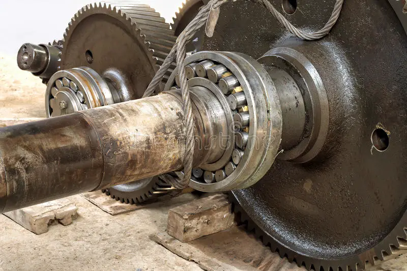
Here is an image, that shows the bearings being dislodged from their containment. The effects of the compressor surge are also contagious and due to excessive shaft vibrations, the gearbox connected between the compressor and the driver is also not spared at the bearings and gear teeth.
The power of a compressor surge is also proportional to the capacities (flow, power, pressure ratio) and even in the case of small turbo compressors, the gear teeth wear out when the impeller rotates in the opposite direction during a surge.
The bottom line is: Always avoid a surge in compressors and other rotating equipment.
Compressor Surge Control
Compressor Surge Control using Anti-surge Valve (ASV)-Cold Gas Recycle
The chief protecting agent of a centrifugal compressor is the anti-surge line/valve that recycles cold gas from the discharge side cooler back to the suction scrubber to keep the operating point away from the surge line.
Compressor Surge Control: Hot Gas Recycle Valve
Although the anti-surge valve (ASV) is the chief protector, in brownfield projects, often the ASV becomes inadequate to deal with a compressor surge due to the addition of new compressors in parallel or series (e.g., booster compressors), change of plant piping or change of vapor composition. In these situations, a necessity arises to recycle more flow for which an additional ASV with quick opening characteristics is installed in parallel to the first ASV. When such solutions still fail to stop a compressor surge event from occurring, a hot gas recycles (a.k.a HGV) is used as a last resort. The second image below shows a gas compressor with hot gas recycles whose operating point moved away from the compressor surge line during an emergency shutdown.
In recent decades, with tools such as dynamic simulation, the quantity of hot gas to be recycled can be determined without recycling immoderate amounts of hot gas that can overheat the gas compressor with bearings and seals failing. Excessive hot gas recycling also shortens the efficacy of the lube oil that is used for lubrication purposes.
The Hot gas recycles valve is always to be used in tandem with the ASV and only during an emergency shutdown (ESD). A hot gas recycle/bypass system consists of piping with an On-Off Valve that is motor operated and can have a full opening time of < 1 sec (for valves between 4” to 16”). For larger On-Off Valves (above 16”), the time is taken to be < 2 sec. In the case of an electric motor-driven compressor, the power source for the motor-operated HGV must be independent lest, during a power failure, the motor-operated HGV becomes futile.
The hot gas piping should also be laid as short as possible between the discharge line and the suction line to have a fast response. During an ESD scenario (e.g., power loss), taking a conservative approach for design purposes, the control output signal from the compressor driver after a trip, takes ~300 milliseconds to reach the Distributed Control System (DCS) and another ~300 milliseconds from the DCS to reach the HGV to open. However, with advances in technology, these timings can be considered at ~100 milliseconds.
In simple terms, lower response time increases the chances of responding faster to a compressor surge.
Deviations from Design Criteria for Compressor surge control
As a thumb rule, the hot gas system is sized for 50% (max) during the FEED stage. However, this needs to be checked with a dynamic simulation study since over-sizing the Hot gas system can cause the compressor to overheat the bearings and seals. As per API 617 (7th Edition, 2002), Clause 2.7.1.3, it states,
As a design criteria, bearing metal temperatures shall not exceed 100°C (212°F) at specified operating conditions with a maximum inlet oil temperature of 50°C (120°F). Vendors shall provide bearing temperature alarm and shutdown limits on the datasheets.
However, clause No. 2.7.1.3.1 of the said document also says,
In the event that the above design criteria cannot be met, purchaser and vendor shall mutually agree on acceptable bearing metal temperatures.
In reality, the Author has seen cases, where this deviation was taken up to ~135 deg.C depending on the manufacturer and believes that this is due to a variety of operating conditions between string test conditions and actual conditions.
Nevertheless, compressor operating temperatures must never exceed the stipulated or mutually agreed values in order to protect the compressor’s internals.
Compressor Surge Control Systems
In today’s world, no piece of machinery can be said to be protected by modern methods without implementing a control system. A compressor surge can occur in a matter of seconds or sometimes even milliseconds giving almost no time for operators to intervene. Hence a control system becomes a part and parcel of the centrifugal compressor package.
Although the good old Proportional-Integral-Derivative (PID) control was enough to avoid a compressor surge by minimizing the compressor recycle flow, it did not aid much in reducing/optimizing the power requirements. With a steady rise in oil consumption since the 1970s, the necessity of energy efficiency, safety, and environmental friendliness became a priority and demanded better control systems. To respond quickly to any process upsets, high computational speeds in controllers also became a necessity. This led to the rise of specialized control equipment known as ‘Black Boxes’ that was the alternative to panel-mounted instruments. Black boxes though addressed response times, suffered from frequent hardware and software revisions. Black box technology was proprietary with its own coding languages and often experienced compatibility issues when interfacing between different manufacturers’ models. This also meant having to sometimes shut down the machinery causing monetary implications and increased downtime if not made part of plant maintenance.
The Advent of a Programmable Logic Controller (PLC) for compressor surge control
With the limitations of using black box technology being recognized, industry honchos realized the necessity of standardizing and generalizing control systems and their respective programming languages. These standardization efforts led to documenting the IEC 61131 (International Electrotechnical Commission Standard for Programmable Controllers) in 1993 and subsequently revised in 2003.
Programmable Logic Controllers (PLCs) provided not only computational power but also were easily integrateable into the compressor controls. PLCs offered the advantage of scalability where new I/O could be added during any form of plant modification/expansion depending on the type of PLC used (e.g., modular or stacked). PLCs also offer Diagnostics capabilities, for example, to trace through the logs of controller output/data during fault analysis.
In earlier systems that depended on the black box principle, a primary PLC is supplemented with an auxiliary PLC that controlled systems like lube oil, seal oil / dry gas seals, startup sequencing, interlocks, etc. This also required interfacing them properly to allow operators to diagnose and do a root cause analysis in the event of, for example, a compressor trip. However, with integrated systems, that used a dedicated control PLC with a backup PLC and the necessary hard wiring, the cost of implementation also comes down while offering better efficiency, diagnostics, generic parts, and scalability.
Some more ready references for you
Introduction to Pressure Surge Analysis
Water Hammer Basics in Pumps
Pipe Stress Analysis from Water Hammer Loads
Centrifugal compressor surge is an internal phenomena –and outlet flow rate is ZERO.
centrifugal compressor surge is a characteristic behavior when inlet flow is reduced and the compressor head developed is so low that it can not overcome the pressure at the compressor discharge. (flow rate is ZERO.)
No outlet gas.(what is the causes of flow reversal within the compressor inlet and outlet (cycle 5 to 20 times per second )
Please explain how the gas return back to discharge and back the compressor inlet and outlet (cycle 5 to 20 times per second ) internally —–No compressor flow outlet –if you don’t have the answer — I have ???
Very knowledgeable and informative blog, thanks for this knowledge .