
What are Pump Affinity Laws?
Pump affinity laws or Pump Laws are used during hydraulic design to calculate the volume, capacity, head, or power consumption of the centrifugal pumps with changing speeds or wheel diameters. These laws are very important in pump design as they express the relationship between the variables that decide the pump performance.
The Pump affinity laws are basically a set of formulas that predict the impact of Change in Pump impeller Diameter and its Rotational Speed on the Pump Head (h), Pump Flow (Q), and Power Demand of the Pump (P). The affinity laws are applied both to centrifugal and axial flows. These laws can also be applied to fans and hydraulic turbines.
Uses of Pump Affinity Laws
Pump Affinity laws are widely used to predict the pump performance at a different speed or with different impeller diameters provided the pump performance curve at a certain speed or impeller diameter is known.
Using the series of ratios that pump affinity laws establish, a pump engineer can predict the performance of the pump subject to changing pump conditions. So, Pump affinity laws are a great tool to help pump engineers.
You can refer to our video article on the same subject by clicking here. To get an update regarding more similar videos please click here and subscribe to our channel.
Types of pump affinity law?
As mentioned above these laws study the impact of impeller diameter & rotational speed of the pump. Hence the affinity laws are framed
- Once keeping the diameter constant (D=Constant) and
- Once keeping the rotational speed constant (N=Constant).
So based on these conditions below mentioned are the cases and relations on flow, head & power consumption of the pump.
Pump Affinity law keeping the impeller diameter Constant
As per the first set of pump affinity laws for a given pump with a fixed impeller diameter:
- The flow of the pump is directly proportional to the change in the speed of the pump. This means there will be the same amount of change in the flow of the pump as the rotational speed of the pump changes.
- The Head of the pump is proportional to the square of speed. This means a change in pump rotational speed will lead to a change in the square root of the pump head.
- Power is proportional to the cube of the speed. This means that when the rotational speed of the pump is increased the power consumption of the pump will be increased by 8 times.
The above points can be presented mathematically as given below
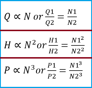
Normally, within the range of normal pump operational speeds, there is no appreciable change in efficiency. Because of this, the first Set of Pump Affinity Laws is reasonably accurate and reliable.
Pump Affinity laws keeping the pump speed constant
As per the second set of pump affinity laws for a given pump with a constant speed:
- The flow of the pump (Pump Capacity) is directly proportional to the change in the impeller diameter of the pump. This means there will be the same amount of change in the flow of the pump as the impeller diameter of the pump is changed.
- The Head of the pump is proportional to the square of the impeller diameter. This means a change in the pump impeller diameter will lead to a change in the square root of the pump head
- Power is proportional to the cube of the impeller diameter. So, when the diameter of the pump is increased the power consumption of the pump will be increased by 8 times.
Mathematically the aforementioned points can be represented as given in Fig. 3.
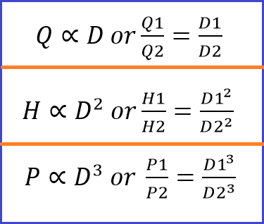
Note that, inaccuracies can be introduced into the predictions of the second set of pump affinity laws as efficiency changes with changes in impeller diameter.
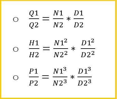
Combined Pump Affinity Law
The flow, head, and power consumption of a pump change can be combined as shown in Fig. 5 when both rotational speed & impeller diameter change.
Example Calculation Explaining Pump Affinity Law
Consider a pump of flow 1000 m3/hr is designed for 1500 rpm. The same pump is required to be operated at 3000 rpm. Find the changed flow of the pump. Assume the diameter of the pump is kept constant.
Solution:
As per the pump affinity law when the impeller diameter is kept constant:
Q∝N or Q1/Q2=N1/N2; So, Q1 = 1000m^3/hr, N1 = 1500rpm, Q2 =? , N2 = 3000 rpm.
Hence, 1000/Q2=1500/3000; Q2=2000 m^3/hr
Hence for the same pumps if the RPM of the pump is doubled flow will also get doubled.
In the same example let’s take Power consumption = 100Kw, so find P2 at the changed RPM.
P∝N^3 or P1/P2=(N1^3)/(N2^3 )
So, 100/P2=(1500^3)/(2000^3 ) Or P2 = 800 kW.
Hence a change in rpm will increase the power consumption of the pump 8 times.
Want to learn more. Here are a few Handpicked articles to add value to your learning process.
NPSH for Pumps: Explanation and Effect
Cause and Effect of Pump Cavitation
Pump Suction Intake Design with Sample Calculation
Types of Pumps used in Process Plants
Major Factors Affecting the Pump Performance
Other pump-related articles
Compressor related articles
Other Mechanical Design related articles
I didn’t think the Flow rate for axial flow pumps is proportional to the diameter (as above) given Q=VA and A is proportional to Diameter squared Wikipedia gives Q is proportional to Diameter cubed?