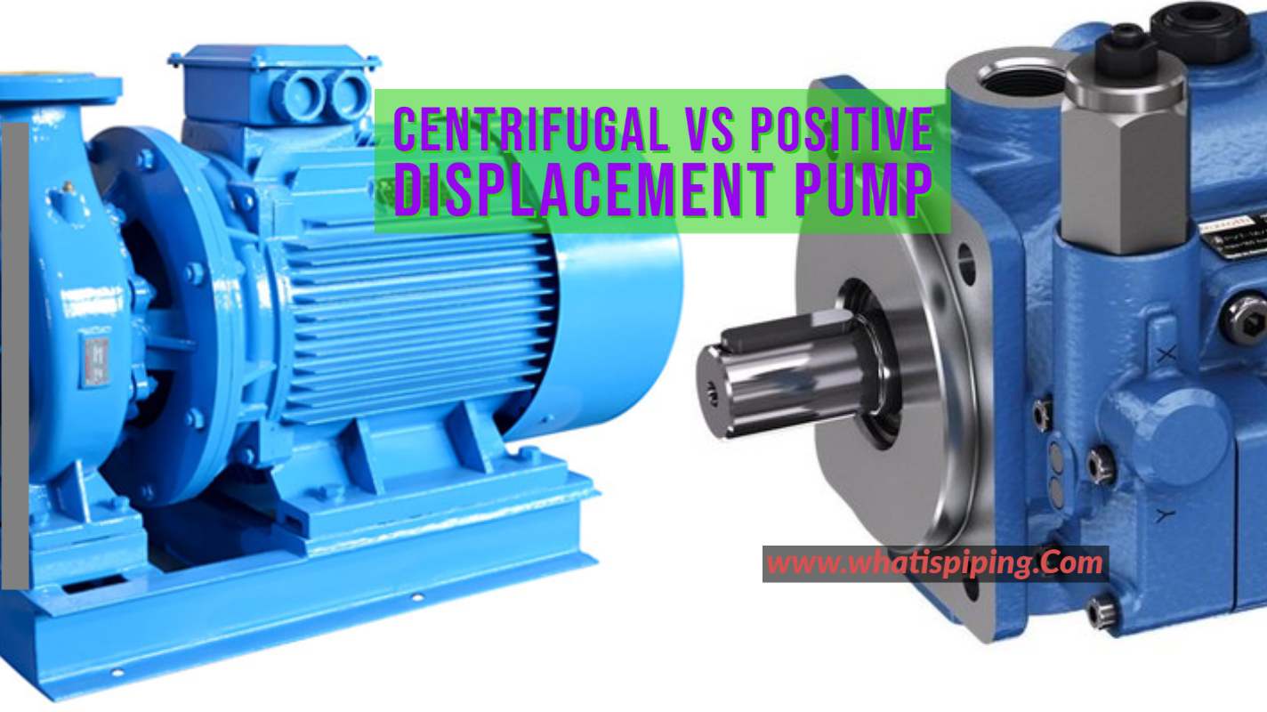
The pump is a device that converts mechanical energy into hydraulic with the help of an external source, it may be centrifugal force through an electric motor. This centrifugal force is generated due to the rotation of the impeller above the suction port of the Pump, which helps in delivering fluid from one location to another via the discharge nozzle outlet. The pump type may be Centrifugal or Positive displacement, the mechanism will change accordingly.
Pump performance curves are very important graphs produced by pump manufacturers. They give information regarding how different parameters like NPSH required, efficiency, and power requirement will behave when the flow is changed. To select the right pump for a specific service, the engineer must know to read the pump performance curves. A pump performance curve is also known as a pump efficiency curve, pump selection curve, pump characteristic curve, or simply a pump curve.
What is a Pump Performance Curve?
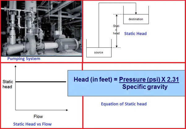
The pump performance curve is the design analysis (or indication) of the pump and how it will operate with respect to the changes in operating parameters such as Pressure (Pressure Head is derived from pressure) & Flow rate.
The factors which are dependent upon the operating parameter are Pressure head, shut-off head, impeller diameter, efficiency, NPHSR, and Power Consumption. We will discuss these terms later in this article.
Generally, the pump performance curve is generated by the pump’s original equipment manufacturer such as Flowserve, Netzsch, etc.
Types of Pump Performance Curves
Generally, there are 5 types of curve representation available which are listed below:
- Head V/S Flow (H-Q Curve)
- NPSHR curve
- Efficiency Curve
- Power Consumption Curve
- Family Curve: It is the curve that includes different functional parameters (Shutoff head, efficiency, impeller diameter, NPSHR within a single curve)
Please refer to the attached pump performance curves in Fig. 1 (first curve) and Fig. 2 (second curve) below. Fig. 2 is a typical example of a family curve.

Cases for which the Pump Performance Curve is drawn or plotted
In general, there are three conditions for which pump performance curves are usually drawn. These are?
- Minimum flow: Minimum flow is the case in which deliverable flow through the pump is in operation.
- Rated Flow: Rated flow is the condition for which the pump is delivering a normal flow rate.
- Maximum Flow: Maximum flow rate is the expected rise in flow rate for future provision.
For Example, the Pump vendor requires the flow rate as Flow (Minimum/Rated/Maximum): 10 / 25 / 40* (m3/h) (Values indicated are typical only).

Important Terms Involved with Pump Performance Curve
A basic understanding of the following terms is beneficial to understand the performance curve for any pump.
Flow: Flow is the quantity of liquid available for pumping application (i.e. amount of flow to be delivered through discharge of pump). It is represented on the X-axis of the Curve. Measurement of Unit is m3/h or GPM.
Differential Pressure Head: The head is the equivalent height of fluid energy due to pressure, velocity, or height above the datum (reference Point). The pressure head is generated because of pressure energy. This parameter is plotted over Y-Axis.
Differential pressure head can be calculated from the equation below:
∆P= rho* acceleration due to Gravity* ∆Height
Here
- ∆P is the difference in pressure available at Suction & discharge.
- ∆H is the difference in height of liquid at suction & discharge (also known as differential pressure head), and
- rho is the density of the Fluid.
Curve Interpretation: The head is indicated on curve 1 with green color. The differential head is inversely proportional to the flow rate. Decreasing the value of the head from 60 to 40 meters over the Y-axis increases the flow on X-Axis from 9 to 12.5 thousand Gallons. Differential pressure head is measured in meters (m) units. Refers to the curve indicated above, as the deliverable or discharge flow required is increased pressure head gets reduced.
Shut off Head: Shut off head is the condition in which the pump gives the highest head. It is a condition in which the pump is designed as a discharge outlet of the Pump and is assumed as closed or blocked condition while in this condition flow corresponding to shut off head is Zero as indicated in the above curve. The shut-off head is also measured in meters (m).
Curve Interpretation: Shut-off head is attained in the case where the curve when the volumetric flow rate is zero. Shut off head is marked on Y-Axis over the curve.
NPSHR: NPSHR stands for Net positive suction head required means that a positive suction head requires to keep the pump safe from cavitation or boils off operation. NPSHR should be always greater than NPSHA (Net positive suction head available). The measuring unit for NPSHR is a meter (m).
Illustration: The basic purpose of NPSHR is to keep the pumping fluid pressure above the vapor pressure; vapor pressure is the state of matter in which phase is to be found in the gas phase (Vapour fraction is equal to 1). A positive suction head needs to be sufficiently more than required to maintain the fluid phase as real & causing the pump to any type of wear.
Curve Interpretation: Refer to curve second, NPSHR is directly proportional to the flow rate, NPSHR increases as the volumetric flow rate is increased; the same is indicated in the curve.
Efficiency: Efficiency is simply defined as the ratio of hydraulic power output to the shaft power input. In the description, hydraulic power is generated by the pump for developing flow rate & discharge pressure. In the shaft power case, this is Power delivered to the pump through an electric motor or external engine. The efficiency of the pump is usually indicated in (%) percentage.
Curve Interpretation: Refer to the indicated first curve as efficiency increases as the flow rate increases, thus reaching up to a specific Efficiency mark where efficiency is highest; this point is called the Best Efficiency Point. Moving on the curve either the left or right efficiency of the pump gets reduced and so on.
For Example: let’s assume a Car gives generally a 20 Km average but at a certain range of speed where the car produces the maximum average. Exactly is the same in the case of the Pump.
Power Consumption: The power consumption term ultimately relates to the efficiency in which shaft and hydraulic power are included.
Curve Interpretation: Refer to the first curve indicated with the orange line, Power consumption is in direct proportion with the flow rate. Power consumption rises as the pump flow increases. This power input’s main purpose is for the pump to produce a discharge flow rate that will be achieved by the external electric motor.
For Example, A 100 Watts bulb consumes high electricity rates than 10 Watts. Consumption is directly dependent on the Output.
Impeller Diameter: As indicated in the second curve, Affinity law defines flow as directly proportional to the Impeller diameter & Speed; the total head developed is directly proportional to the square of the Impeller diameter & Speed; power consumed through the pump is directly proportional to the cube of impeller diameter & speed.
Curve Interpretation: Refer second curve Impeller diameter is indicated with three cases as in the curve, the Maximum case head achieved by the pump is maximum and thus higher the head lowers the volumetric flow rate. The same scenario is applicable in the Rated & minimum case of the impeller. The impeller diameter curve starts from the Y-Axis indicated in black color for all three cases (Max. / Rated / Min).
Image Credit: https://commons.m.wikimedia.org/wiki/File:Pump_Characteristic_curve.png


Good information
NPSHa > NPSHr