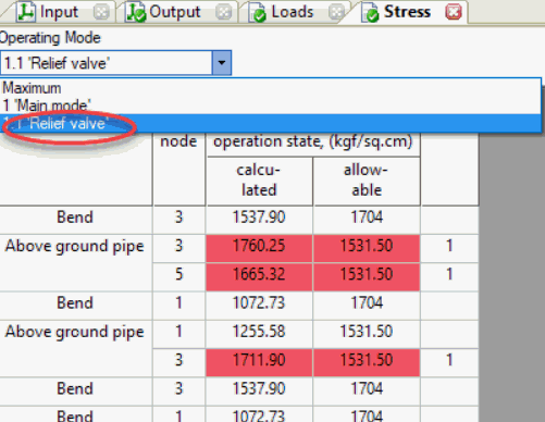
Start-Prof can estimate the support loads and stresses caused by relief valve discharge by an equivalent static method.
The relief valve discharge thrust load acts on elbow 28. In Start-Prof it should be applied at the end of the elbow in node 29.
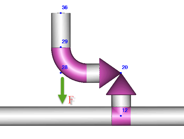
Download this piping model file. See how to open the piping model file
There’s two methods to estimate the dynamic equivalent thrust force F:
- ASME B31.1 method
- Direct calculation of V1 и P1 by special software like Hydrosystem
ASME B31.1 Method
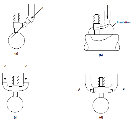
Equivalent dynamic thrust force can be estimated by the equation:
F = DLF ∙ F1
where
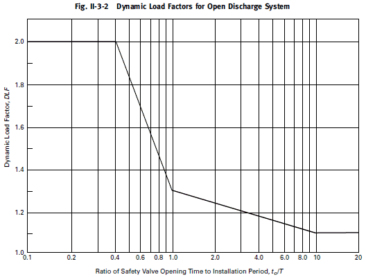
DLF – dynamic load factor, depending on the first natural period of piping. If the period is unknown the DLF=2.0.
F1 – static reaction force, kgf. May be computed by the following equation:

where
W – mass flow rate (relieving capacity stamped on the valve by 1.11), kg/sec
gc=9.81 m/sec² – gravitational constant,
Pa – atmospheric pressure, kgf/sm²
A1 – exit flow area, sm² A1=p∙(D-2t)²/4
V1 – exit velocity (node 36), m/sec

P1 – static pressure, kgf/sm²

h0 – stagnation enthalpy at the safety valve inlet, MJ/kg
J = 101970.408 m*kgf/MJ
a, b – constants according to the table below
| Steam Condition | a, MJ/kg | b |
| Wet steam
<90% quality |
0.6769 | 11 |
| Saturated steam
≥90% quality 1.05 kgf/sm² ≤ P1 ≤ 70.31 kgf/sm² |
1.9143 | 4.33 |
| Superheated steam
≥90% quality 0.07 kgf/sm² ≤ P1 ≤ 140.61 kgf/sm² |
1.93291 | 4.33 |
Example
Example project file: ReliefValve.ctp. See how to open the piping model file
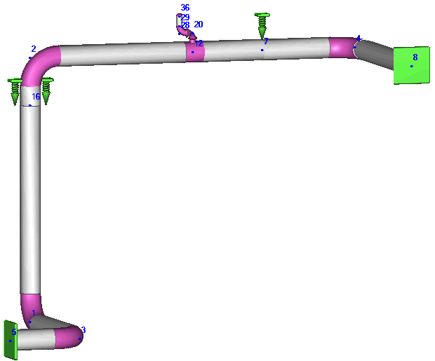
Input data:
-
Diameter of discharge pipe: 21.9 sm
-
Wall thickness of discharge pipe: 1.6 sm
-
product: Saturated steam
-
relief valve relieving capacity: 48 kg/sec
-
Steam pressure: 64 kgf/sm²
-
Steam temperature: 538°C
Calculation:
A1=p∙(D-2t)²/4 = 3.14159∙(21.9-2∙1.6)²/4 = 274.65 sm²
a = 1,9143 MJ/kg
b = 4.33
W = 48∙1.11 = 53.28 kg/sec
stagnation enthalpy for steam at 70 kgf/sm² and 538°C h0 = 3,506 MJ/kg
P1=53.28/274.65*(4.33-1)/4.33*(2*(3.506-1.9143)*101970.408/(2*4.33-1)/9.81)^0.5 = 9.8 kgf/sm²
V1 = (2*9.81*101970.408*(3.506-1.9143)/(2*4.33-1))^0.5 = 644.77 m/sec
F1 = 53.28*644.77/9.81 + (9.8-1)*274.65 = 5919 kgf
F = DLF ∙ F1 = 2*5919 = 11838 kgf
Create additional occasional force loading 1.1 in operation mode editor:
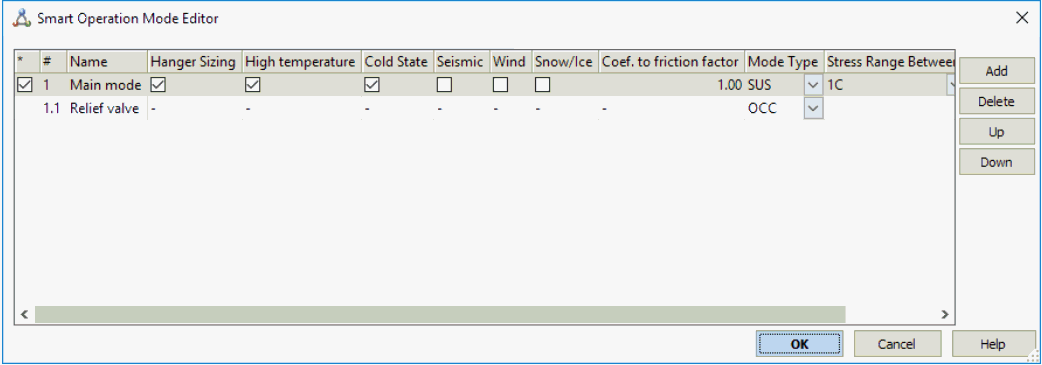
If we have more relief valves, then we should add more additional modes (1.2, 1.3, etc.) if it’s open not simultaneously.
Apply dynamic thrust force at node 29 for mode 1.1:

Support loads due to relief valve thrust load:

Stresses due to relief valve thrust load:
