
Pipe wall thickness calculation is one of the important basic activities for every piping engineer. Process plants deal with the fluids that flow inside the pipe at high pressure and temperature. So, the pipe deals with high circumferential pressure which can cause the bursting of the pipe if the pipe schedule or thickness is not enough. Hence, The designers need to find out the required piping thickness as per section “304.1.2 of ASME B31.3” to resist the internal line pressure. The operation must be leak-free.
In this article, I have simplified the pipe thickness calculation procedure. A sample pipe wall thickness calculation problem is discussed mentioning the calculation steps. Process Piping Code ASME B31.3 is used as the basis for the Pipe thickness calculation.
Why is Pipe Thickness Calculation Important?
The minimum required thickness of a pipe must be calculated to ensure
- The selected pipe will be able to withstand the pressure at the design temperature without failure.
- To avoid being over-conservative and thus optimize cost.
- If a supplied pipe is not from a standard pipe class defined in a project, then the pipe thickness calculation will ensure that the pipe can withstand the internal pressure without rupturing or leaking. Failing to specify the correct thickness can result in catastrophic failures, posing safety hazards and potential environmental damage.
Background Theory of Pipe Wall Thickness Calculation
The calculation of pipe wall thickness is a critical aspect of piping design, ensuring that pipes can safely withstand the internal pressure and other loads they may encounter during operation. A pipe is considered to be a thin-walled vessel and the wall thickness of such elements is calculated using Barlow’s formula. The pipe wall thickness is proportional to the internal pressure of the pipe. The hoop stress equation S=PD/2t is the base equation for pipe thickness calculation in all codes. Depending on the specific code requirements the same formula is modified by using different different factors.
Pipe Thickness Calculation Using ASME B31.3
Some Important Points regarding Pipe thickness Calculation
Before starting the piping thickness calculation, the engineer should be aware of the following points:
- Process plants are designed for 20 years or 7000 cycles. (Considering 1 cycle per day; the Total number of cycles in 20 years=20*350=7000 cycles)
- Pressure and temperature can vary from line to line and from time to time.
- Fluid could be corrosive and toxic in the system.
- Corrosion allowance for pipe material is decided based on service fluid. Typical values are 3 mm for Carbon Steel and zero mm for stainless steel.
- Mill tolerance for the seamless pipe is 12.50% and 0.3 for the welded pipe.
How do I Calculate Pipe Thickness? | Pipe Thickness Calculation Example
Let’s consider the following details for the pipe thickness calculation of a seamless Carbon Steel pipe.
- MOC (Material of Construction) of the pipe – ASTM A106 Gr. B
- NPS (Nominal Pipe Size) – 4”
- Manufacturing type of the pipe (SMLS, EFW, ERW) – Seamless (SMLS)
- Design Pressure (PSI) – 1200 PSIG
- Design Temperature – 500° F
- Mechanical, corrosion, and erosion allowances – 3 mm
- Mill Tolerance – 12.50% of the thickness
Pipe Wall Thickness Calculation Formula | Equation for Pipe Thickness Calculation
As per clause 304.1.2 (a) of ASME B31.3, the internal pressure design thickness for straight pipes with t<D/6 can be calculated using the following formula (Equation (3a):
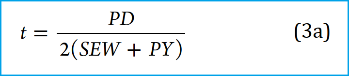
Here,
- P: Internal Design Gage Pressure=1200 PSIG as per problem definition
- D: Outside Diameter of the pipe
The equation for the pipe wall thickness is based on the outside diameter of the pipe, rather than the inside diameter. This is because the outside diameter of the pipe is constant, it is independent of the wall thickness. Hence, the pipe wall thickness can directly be calculated easily using the pipe’s outer diameter.
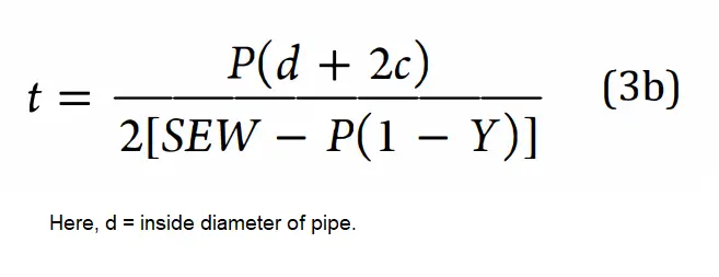
ASME B31.3 provides another formula (Equation 3b) for calculating pipe thickness based on the inside pipe diameter as mentioned in Fig. 2 below. However, this equation is seldom used but is provided here for academic purposes.
In the pipe thickness calculation methodology explained below, we will use the pipe thickness calculation formula mentioned in Fig. 1 containing the pipe’s outer diameter.
Explanation of the terms used in ASME B31.3 Pipe Thickness Calculation Equation
Pipe Outside Diameter, D
The outside diameter has to be taken from the below standards-
- ASME B36.10M: for ferritic steel (seamless & welded wrought steel pipes).
- ASME B36.19M: for austenitic steel (stainless steel pipes)
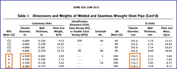
So from Fig. 3, D= 114.3 mm
S: Allowable Stress value of the Pipe Material (A 106-B) at Design Temperature (500° F)
Refer to Table A-1 (or Table A-1M) of the ASME B31.3 (Fig. 4) for getting the value of the allowable stress. Travel in the horizontal (x) direction for allowable stress value and vertical (y) direction for pipe material, and the match point to get the value (refer to Fig. 4). If required, use interpolation to calculate the middle value.
Note: the value of the allowable stress in Table A-1 is given in KSI, So we need to convert the value in PSI.
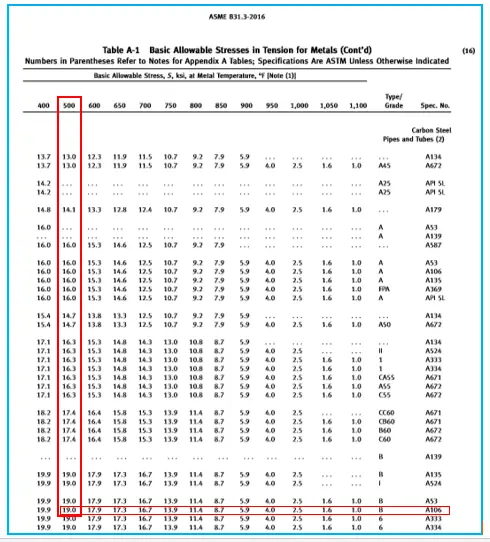
As per Fig. 4, the allowable stress for ASTM A106 Gr. B is 19,000 psi at 500°F.
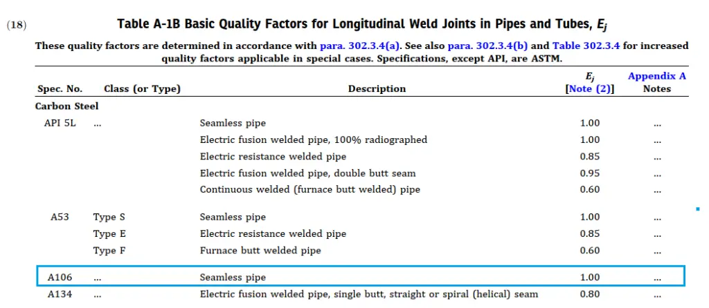
E: Quality factor
Quality Factors are used in Pressure Design and applied at Longitudinal and Spiral Weld Joints and for Castings. The maximum value of quality factors is 1.0.
The value of E, Longitudinal Weld Joint Quality Factor, or Casting Quality Factor can be found in Table A-1A or Table A-1B of the ASME B31.3. The weld joint factor (E) is 1 for our problem case (Refer to Fig. 5).
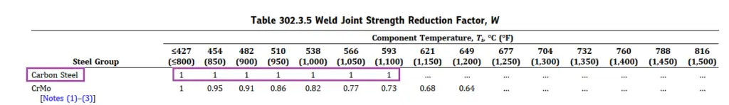
W: Weld Joint Strength Reduction Factor
As per section 302.3.5(e) of ASME B31.3, The weld joint strength reduction factor, W, is the ratio of the nominal stress to cause the failure of a weld joint to that of the corresponding base material for an elevated temperature condition of the same duration. It only applies at weld locations in longitudinal or spiral (helical seam) welded piping components.
Weld Joint Strength Reduction Factors are used because at elevated temperatures the weld joint creep rupture strength can be lower than the base metal.
The value of W can be found in Table 302.3.5 of ASME B 31.3 (Refer to Fig. 6) and for our problem the value of W=1
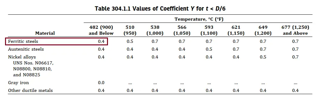
Y: Values of Coefficient from Table 304.1.1,
The factor “Y” depends on temperature. At elevated temperatures, factor Y increases leading to a decrease in the calculated required pipe wall thickness.
Refer to Table 304.1.1 of ASME B31.3 for finding the value of Y, It is Valid for t < D/6 and materials shown below The value of Y may be interpolated for intermediate temperatures. For material A106 Gr. B, Y is given 0.4 (refer to Fig. 7)
Pipe Thickness Calculation Steps
Step 1. Put the above values in the equation shown in Fig. 1
t=(1200*114.3)/{2(19000*1*1+1200*0.4)}=3.52 mm; Hence calculated thickness (t)= 3.52 mm
Step 2. Add the corrosion to the calculated thickness.
tc = t + c = 3.52 + 3
tc = 6.52 mm
Step 3. Add the mill tolerance to the thickness after adding the corrosion value.
tm = tc + 12.50 % of the pipe thickness
tm =tc/0.875 =6.52/0.875 = 7.45 mm (This is required thickness)
Step 4. Select the next Ordering thickness available in ASME B36.10M considering the required thickness.

So from Fig. 8, The Ordering thickness is 8.56 mm or Schedule 80.
Note:
1. Ordering thickness for seamless pipe will always be the next greater value available from Schedule to schedule.
2. Whereas for welded pipe any next greater value will be the ordering thickness.
3. Extra thickness can be calculated by ordering thickness minus the required thickness = (8.56 – 7.45) = 1.11 mm.
Use of the Extra thickness available in the pipes
- For calculating the life of a pipe after 20 years.
- For calculating the maximum pressure holding capacity of the pipe.
- For checking extra thickness is sufficient to take care of thinning, if the same pipe is used for manufacturing the bend.
- The extra thickness also minimizes deflection and reduces the number of pipe supports.
- To compare with flange pressure holding capacity, to declare pipe is stronger than the flange.
Parameters Affecting Pipe Thickness
By now you must have understood all the parameters that affect the pipe thickness. The parameters are mentioned below for easy understanding
- Design Pressure: With an increase in internal design pressure the thickness of a pipe increases.
- Design Temperature: With an increase in the design temperature, the allowable stress value reduces which, in turn, increases the pipe thickness.
- Pipe Outer Diameter: With an increase in piping OD the pipe thickness corresponding to the same pressure increases.
- Pipe Material: With a change in pipe material the stress value changes and hence the calculated pipe thickness. For example, for the same pressure, the wall thickness for CS and SS pipe material will be different.
Assumptions for Pipe Thickness Calculation
For the above-mentioned pipe thickness calculation steps following ASME B31.3, the following assumptions are made
- The pipe is a thin cylinder and the value of thickness t is less than D/6.
- The value of P/(SE)<0.385
- The pipe is subjected to internal pressure only, For external pressure thickness calculation additional parameters need to be considered as mentioned here.
ASME B31.3 Pipe Thickness Calculator
A pipe thickness calculator is a tool that calculates the pipe thickness when all required inputs are supplied. Pipe wall thickness calculators can be developed in the form of an Application, Visual Basic program, or Excel sheet program. All equations are programmed inside the utility to help piping professionals calculate design pipe thickness with ease.
Inputs Required for the Pipe Thickness Calculator
To use any pipe thickness calculator (attached below), you have to be ready with the following inputs:
- The Pipe material of construction for knowing the Allowable Stress, in a consistent unit
- Pipe Outside Diameter, in consistent unit.
- Pipe internal design pressure
- Design temperature, to select the allowable stress.
- Quality Factor, E from Table A-1A/A-1B of the code based on the pipe construction type: Seamless, EFW, ERW, etc.
- Co-efficient Y from Table 304.1.1
- Corrosion allowance for material and operating conditions.
- Mechanical allowance.
- Mill tolerance.
A pipe thickness calculator using an Excel sheet is attached herewith for your reference. The pipe thickness calculation formula is also mentioned inside the calculator.
Video Tutorial on Pipe Thickness Calculation
Refer to the following video tutorial to further clarify your doubts about Pipe thickness calculation using B31.3
Still in doubt!! Simply click here and attend this course to clarify all your doubts from industry experts.
Few more useful Resources for you.
Pipeline wall thickness calculation with example
Meaning of Pipe Schedule / Schedule Numbers?
how we use the extra wall thickness available for calculating the life of a pipe after 20 years?
what is the relation between the service life (20 years) and cycles (7200 cycles)? and how it affect the original wall thickness calculations?
Hi,
Corrosion allowance is decided based on the service life of the plant, for our sample problem it is taken 3 mm for 20 years or 7200 cycles. If the project required plant life more than 20 years then the corrosion allowance will be taken more as per the number of years.
Therefore, the thickness of the pipe (Considering the same operating condition) for plant life 20 years and plant life 30 years will be different (will be greater for 30 years).
For calculating the life of the pipe after 20 years use the below formula
Life of Pipe after 20 years = (extra thickness available in the pipe)/(corrosion allowance per year)
Where,
extra thickness for our sample problem was 1.11 mm
corrosion per year = 3mm / 20 years = 0.15 mm
So,
Life of the Pipe after 20 years = (1.11)/(0.15) = 7.4 years
what is the relation between the figure 20 years and 7200 cycles?
Best regards
why not selecting 7.92 from chart
as it is not in front of the schedule number.
for seamless pipe, we take the value of the thickness schedule to schedule only. it will be easily available in the market.
For plant piping per B31.3, better to use Scheduled pipes (that is Sch. 40, Std., 80, XS, 160, XXS etc.
For Cross-country pipelines, we use the next thickness of the chart for economic purposes.
This is awesome! Thank you.
This means that the pipe can last about 7 years more after which it has to be changed…
What is the basis for corrosion thickness/erosion thickness selection of 3 mm for 20 Years?
Hi,
There is no corrosion allowance exactly specified in ASME B31.3. Corrosion allowances are normally established by the end-user and are somewhat based on industry tradition or practices. 3 mm for CS piping is a common standard.
Humidity, temperature, rain, wind, impurities, metal wet times, and the types of the fluid flowing through pipe have an effect on the corrosion rate. so corrosion allowance may vary from places to places.
The relation between 20 years and 7200 cycles is simple. It assumes one temperature cycle per day (24 hours cycle) and 20 years are approximately 7200 days. Ideally, it should be 7300 cycles.
I will be glad if you can add the calculation criteria for threaded pipes in the calculation. So that all major points will be covered.
hi, can anyone say about non metallic pipe wall thickness calculation
Hello Rehan thanks for the good job and detailed steps, I really love your posts. Pls can somebody learn to be a piping engineer from your webinars if one is coming from another industry like manufacturing although a mechanical engineer who has spent so many years in FMCG. I really love to be professionally relevant even after quitting job so I would prefer going into piping engineering, so. what assistance can the webinar render to me. Thanks.
how to calculate the BWSC pipe thickness?
Can i use the same above formula if the internal pressure of gas is above 250 bar?
Mr Rehan!
Is it necessary to take corrosion allowance for SS piping
For SS Piping Corrosion Allowance is not required to be considered.
Corrosion allowance is 3mm for cs material and for ss material is zero mm
Should we add or subtract the mill tolerance from the calculated thickness? Because this tolerance can go both + and -ve, there is a chance that calculated thickness value may be higher than the procured pipe. Hence it will not have the required thickness for the above mentioned service conditions. isn’t it safe to calculate the thickness by subtracting the mill tolerance from the calculated thickness?
Mill can’t produce the exact dimension from our calculated thickness, as you said the tolerance may go plus or minus while producing pipes, obviously, if the wall thickness goes less than our calculated thickness mean pipe may not withstand/sustain for the 20 years or 7200 cycle. Considering this factor mill tolerance as 12.5% for ferritic steels will give extra wall thickness, so that it will be added from the calculated thickness after adding the corrosion allowances.
why Ordering thickness for seamless pipe will always be the next greater value available from Schedule to schedule, Whereas for welded pipe any next greater value will be the ordering thickness? I mean why for seamless next greater vale not be selected whereas next schedule?
The same question as you. And why we cannot select any next greater value Schedule for seamless ordering thickness? What is the maximum requirement of extra thickness for each pipe size?
Ex: If the extra thickness is below 1mm, could we select another next greater value schedule?
The final calculation of mill tolerance addition is not correct.
If we have have 6.52mm thickness after addition of the corrosion allowance, 12.5% of 6.52mm will be 0.815 and NOT 0.875 ((12.5/100)*6.52)). Addition of 0.815mm (mill tolerance) to 6.52mm will give 7.335mm and NOT the 7.45mm obtained as final answer.
Also, why did you use the mill tolerance to divide the thickness instead of addition of the mill tolerance to the thickness?
yes i was also confused about this
tm = tc + 12.50 % of the pipe thickness ™
which means,
tm = tc + 0.125 tm
tm(1-0.125) = tc
tm = tc / 0.875 = 6.52 / 0.875 = 7.45 mm
We use to weld flange of 150 Lb rating with 106 gr B pipe 40 sch designed to withstand 1200psi..it means we can use even lesser thickness of pipe for general pressure service..
Isnt we should be welding 1500 lbs flanges with with pipe design for 1200 psi
Hi!
Any sample calculation considering pipe threading? Thanks !
What is the meaning of … in the above-referred code page?
For 1″ thick by order I can get = 0.875″ thick pipe.
if, I order 0.5″ thickness with 12.5% = 0.5*0.125=> 0.4375″. correct?
then why you divide the value by 0.875???
Mr. Khan – enjoyed reading your simple, step-by-step approach to pipe wall thickness calculation (per B31.3). Do have a question…do you know the significance of adding PY in the denominator, as this decreases the calculated wall thickness. As temperature increases, Y also increases leading to a smaller wall thickness (t). This is counter-intuitive (you would expect the wall thickness (t) to increase as temp. increases.
What about cryogenic services? what is stress value of A358 pipe (SS) for design temperature -111°c
hi
i would like to know about calculation and check of thickness sub sea polyethylene100 pipe 80m under sea (external pressure:8 barg and internal pressure is atmospheric pressure)outside dim.:800mm,first approximation thickness is 38.2mm and ambient temperature is 15 c.
best regards
bagheri
we have one case for a Hydrogen line outlet of the compressor having 420 bar pressure at 75 and the construction material is SS316 ? what is your suggestion for piping thickness calculation?
Dear experts,
I am absolutely perplexed with the mill tolerance concept.
Do we need to add or divide.
I see you mentioned 12.5% for addition and 0.875 for division.
Please explain. highly appreciated your response.
And one more doubt is about required thickness and minimum thickness.
which should have greater values.
how to calculate the minimum wall thickness for the pipe line which t greater than D/6 value.Please mention th e formulae for that calclation
304.1.2(b)
(b) For t ≥ D/6 or for P/SE > 0.385, calculation of pressure design thickness for straight pipe requires special
consideration of factors such as theory of failure,
effects of fatigue, and thermal stress.
We got this case for 1/2″ tubes.
Does it mean verification by Caeser would be enough?
When explaining each term of the thickness equation, actually you have not explained why „Y“ appears in the denominator. Is it known to you and, if so, could you please share your thoughts with us?
Hi Anup,
I believe you should not add the mill tolerance to the required thickness; it is more of a check with the selected schedule per specification. What I mean here is we should minus the mill tolerance from the schedule and check if it is more than the required thickness which includes all other tolerances(but not mill tolerance).
I would request you to see the sample S301.2 (ASME B31.3 2016)in which a sample eg is shown.
Let me know your thoughts.
how to calculate the hydraulic cylinder piston thickness or end-plug thickness.