
A pressure relief valve is used to release excess pressure from a system during overpressure situations thus avoiding catastrophic failure. So, a Pressure relief valve is an important process safety device and is widely used in the chemical, petrochemical, power, and oil and gas industries. The pressure relief valve (PRV) is designed to open at a predefined set pressure. So whenever the system pressure exceeds the set pressure, the PRV pops and releases the overpressure and when the excess pressure is removed the PRV closes again. The main advantages of installing a pressure relief valve in a system are:
- They vent the fluid to safeguard the system from overpressure.
- They reclose and prevent loss of fluid when system pressure returns back to acceptable.
- Installation of the PRV system minimizes damage to system components.
- They are reliable and versatile
What are Relief Events?
Relief events are obligatory events that prevent efficiency or performance and increase cost but must be met considering the safety of the operating plant. Examples of potential relief events are
- External fire
- Flow from a high-pressure source
- Heat input from associated equipment/ external source
- Pumps and compressors or other equipment failures.
- Failure of Cooling Medium
- Ambient heat transfer
- Failure of the Control system
- Liquid expansion in pipes and surge
- Blocked discharge, Gas blowby
- Failure of the Condenser system
- Chemical reactions
- Operating error
- Closed Outlets
- The entrance of Volatile Fluid
Potential Lines of Defense against Relief Events
To act against the above-mentioned potential relief events the following defense methods are followed.
- Inherently Safe Design
- Low-pressure processes
- Passive Control
- Overdesign of process equipment
- Active Control
- Install Relief Systems
What is a Relief System?
A relief system is an emergency system used to safeguard plants during relief events by reducing pressure or discharging gas during abnormal situations. The relief system consists of
- A relief device, and
- Associated lines and process equipment to safely handle the material ejected
Why Use a Relief System?
Installing relief systems in operating plants is a must from the process and technical safety points as
- Inherently Safe Design simply can’t eliminate every pressure hazard
- Passive designs can be exceedingly expensive and cumbersome
- Relief systems work!
Code Requirements for relief system design
General Code requirements include:
- ASME Boiler & Pressure Vessel Codes
- ASME B31.3 / Petroleum Refinery Piping
- ASME B16.5 / Flanges & Flanged Fittings
Relieving pressure shall not exceed MAWP (accumulation) by more than:
- 3% for fired and unfired steam boilers
- 10% for vessels equipped with a single pressure relief device
- 16% for vessels equipped with multiple pressure relief devices
- 21% for fire contingency
Locating Pressure Relief Valves
The location of Pressure Relief valves is decided by Process Engineers. They mention the PRV requirements in the P&ID. Below are the General guidelines on where relief devices are required, although there are likely to be other special cases in any process.
- All vessels
- Blocked in sections of cool liquid lines that are exposed to heat
- Discharge sides of positive displacement pumps, compressors, and turbines
- Vessel steam jackets
- Low-pressure storage tanks require both vacuum and pressure relief devices since tanks are typically not designed for full vacuum.
- Wherever formal hazard identification procedures such as Hazard and Operability (HAZOP), Process Hazard Analysis (PHA) indicates
- Piping systems where overpressure can arise due to process control failure.
Types of Pressure Relief Valves
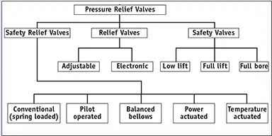
Conventionally Pressure relief valves are categorized into the following three groups:
- Relief Valve
- Adjustable
- Electronic
- Safety Valve
- Low Lift
- High Lift
- Full Lift
- Safety Relief Valve
- Conventional spring-loaded safety relief valve pilot-operated
- relief valve
- Balanced-bellows type relief valve
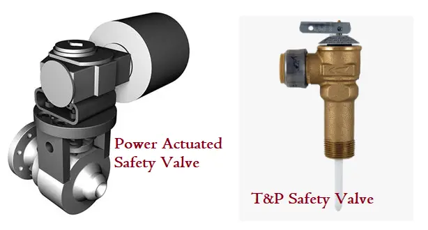
- Power actuated
- Temperature and Pressure actuated relief valve
The above-mentioned pressure relief valve types are produced in graphical form in Fig. 1 below
Relief valves are spring-loaded and characterized by gradual opening and closing. They are actuated by the upstream pressure and are suitable for incompressible fluids. Adjustable relief valves allow the pressure setting adjustment through the outlet port. Electronic relief valves offer zero leakage with electric controls to monitor and regulate the system pressure.
On the other hand, safety valves are used for compressible fluids (gas and vapors) and are characterized by the rapid action of opening and closing. Safety valves are widely used in steam plants for boiler overpressure protection. They are classified into three groups based on the amount of travel or lift during the pop-up. Low-lift safety valves have a small capacity and the valve lifts 1/24th of the bore diameter. High-lift safety valves travel 1/12th of the bore diameter. Whereas Full-lift safety valves travel at least 1/4th of the bore diameter and are best suited for steam services.
The safety relief valve can be used for gas or liquid service depending on the application. They have the characteristic of both rapid and gradual opening.
Conventional Pressure Relief Valve
Spring-loaded conventional pressure relief valves are best suited for applications where excessive back pressure is absent. The back-pressure directly affects the operational characteristics of these PRVs. Refer to Fig. 2 which represents a conventional safety relief valve with its basic elements.
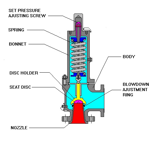
There are three basic components of a conventional pressure relief valve
- An inlet nozzle to be connected to the system requiring protection.
- A movable disk for fluid flow control, and
- A spring for controlling the disk position.
While designing a conventional pressure relief valve, consideration of seat leakage to be checked as leakage means continuous loss of system fluid and the valve seating surface can be damaged. Depending on the seating material, conventional pressure relief valves are classified into the following two types:
- Metal-seated valves, and
- Soft-seated valve
Pros & Cons of Conventional Pressure Relief Valves
Advantages
- Most reliable type if properly sized and operated
- Versatile — can be used in many services
Disadvantages
- Relieving pressure affected by back pressure
- Susceptible to chatter if built-up back pressure is too high
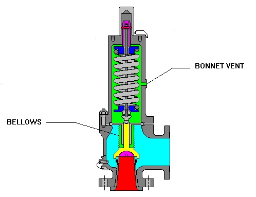
Balanced Bellows Type Pressure Relief valve
To reduce the effects of backpressure, spring-loaded balanced bellows pressure relief valves (Fig. 3) are developed. The PRV design incorporates a bellow that offsets the effect of back pressure. The bellow isolates the spring, bonnet, and guiding surfaces from direct contact with the process fluid.
Typically when back pressure is variable and exceeds 10% of the set pressure, a balanced-bellows type pressure relief valve is used.
Pros & Cons of Balanced Bellows type Pressure Relief Valve
Advantages
- Relieving pressure not affected by back pressure
- Can handle higher built-up backpressure
- Protects spring from corrosion
- Possess good temperature and chemical properties
Disadvantages
- Bellows are susceptible to fatigue/rupture
- May release flammables/toxics into the atmosphere
- Requires a separate venting system
There are two types of balanced bellows safety relief valves:
- Balanced bellows
- Balanced bellows with auxiliary balancing piston
Pilot-operated Pressure Relief Valves
A pilot-operated safety relief valve is a pressure relief valve where a self-actuated auxiliary pressure relief controls the pressure-relieving. The opening or closing of the relief valve is governed by the pressure of the flowing medium. A pilot is used to sense the process pressure and to pressurize or vent the dome pressure chamber, which controls the valve opening or closing. Three main components consist of a pilot-operated pressure relief valve (Fig. 4)
- the main valve,
- a floating, unbalanced piston assembly, and
- an external pilot.
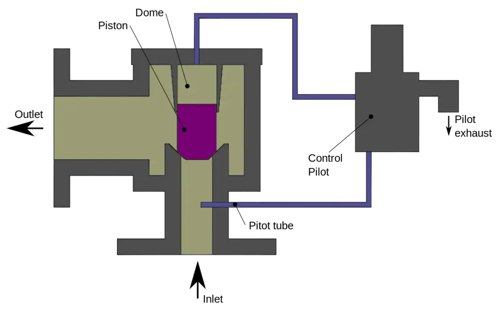
The pressure on the top side of the main valve’s unbalanced moving chamber is controlled by the pilot. Generally, a resilient seat is attached to the lower end.
Advantages of Pilot-Operated Pressure Relief Valve
The main advantages of pilot-operated safety relief valves are:
- The set pressure is unaffected by the valve backpressure.
- As the system operating pressure decides the opening of the relief valve, the system can be operated at maximum working pressure.
- Economical as compared to other types.
- Less susceptibility to chatter.
Pilot-operated Pressure relief valves can be classified based on various parameters as mentioned shown below:
- Depending on the type of moving members
- A piston-type.
- A diaphragm-type.
- Based on the type of pilots
- A pop-action pilot
- A modulating-action pilot
- Based on the flow of pilots
- A flowing-type pilot.
- A non-flowing-type pilot
Power Actuated Pressure Relief Valve
Power-actuated pressure relief valves (Fig. 5) are controlled by a device requiring an external power source. Energy sources like water, electricity, or steam control the opening and closing of the pressure relief valve. They are mostly used for forced-flow steam generators with no fixed steam or waterline and in nuclear power plants.
Temperature Pressure actuated Pressure Relief Valves
A temperature and pressure-actuated pressure relief valve (also known as T&P safety relief valve-Fig. 5) is actuated by the temperature or pressure of the inlet side of the relief valve. The valve consists of two primary controlling elements, a spring, and a thermal probe. They serve dual purposes.
- Prevention of temperature rise above specified and
- Prevention of over-pressure from rising above a specified value.
They are mostly used for vessels, tanks, and heaters carrying hot fluids.
Vacuum Relief Valve
A Vacuum Relief Valve is designed to prevent an excessive internal vacuum by admitting fluid. Once the normal condition is restored, they reclose and prevent further fluid flow.
When to Use a Spring-Operated Pressure Relief Valve
- Losing entire contents is unacceptable
- Fluids above the normal boiling point
- Toxic fluids
- Need to avoid failing low
- Return to normal operations quickly
- Withstand process pressure changes, including vacuum
Pressure Relief Valve Accessories
A number of pressure relief valve accessories help the valve in its operations to achieve the intended use. They are:
- Test gags hold the safety valve closed during the hydrostatic test.
- Lifting mechanisms to lift the valve disk. Available in three types
- plain lever,
- packaged lever, and
- air-operated lifting devices.
- Bolted caps are available for standard pressure relief valves in addition to the screwed caps.
- Valve position indicators for remote indication of the PRV opening
Working of a Pressure Relief Valve
For a spring-loaded pressure relief valve, the spring force holds the disk in position keeping the valve in a closed position. When the pressure of the line exceeds the set pressure, the disk starts to lift allowing the fluid to flow through the outlet and release pressure. With a further increase in inlet pressure, the disk lifts further. When the disk has traveled to its designed value, the valve is fully open and the system pressure is released.
Once the overpressure inside the system falls below the spring force the spring pushes back the disk in positive to close the valve preventing further release of fluid.
For pilot-operated pressure relief valves, the inlet pressure is directed to a small safety valve that acts on top of the piston. As the top area of the piston is designed greater than the bottom area under fluid contact, the pressure on top is higher which pushes the piston to close the relief valve. When the inlet pressure rises above the set pressure, a net upward force acts on the piston forcing the piston to pop up and release the pressure.
Codes and Standards for Pressure Relief Valve
Pressure relief valves are governed by codes and standards. The most widely used pressure relief valve codes and standards are:
- ASME BPVC (Sec I, Sec III, Sec IV and Sec VIII)
- ISO 4126
- API 520
- API 521
- API 526
- API 527
- PED 97/23/EC
- EN4126
- JIS B 8210 (Japan)
- KS B 6216 (Korea)
- SAA AS 1271 (Australia)
Relief Valves – Pressure Terminologies
Let us understand some additional basic terms which are widely used in relation to relief valves.
The set pressure is the pressure at which the relief valve starts to open. It is normally the same as design pressure and is measured at the valve inlet. For spring-operated relief valves small amount of leakage (simmer) starts at 92-95% of the set pressure.
Overpressure is the pressure increase over the set pressure of a pressure relief device, during discharge and is usually expressed as a percentage of the set pressure (normally overpressure is set to pressure +10%) Relief valve achieves its full discharge capacity at overpressure
Accumulation is the pressure increase over the DP/ MAWP of equipment during discharge through the protecting pressure relief valve and is usually expressed as a percentage of the DP/MAWP.
Generally there is confusion between the terms Accumulation and Overpressure. When we say ‘accumulation’, it means we are talking about the vessel, and when we say ‘overpressure’, we are talking about the pressure relief valve
Blowdown is the pressure difference between the set pressure and the pressure at which the valve reseats. It is usually expressed as % of the set pressure and refers to how much the pressure needs to drop before the valve reseats.
Reseat Pressure is the pressure at which the valve is fully closed.
The cold differential test pressure is the pressure at which the valve is adjusted to open on the test stand, and incorporates the effects of superimposed back pressure and operating temperatures
Pressure Relief Valve Sizing
Correct sizing of Relief Valves is crucial. If the relief valve is undersized it may not relieve sufficient quantity of fluid to prevent pressure build-up. This consequently may result in high pressure. If the relief device is oversized, the relief valve may become unstable during operation.
The sizing of a pressure relief valve is done by the Process team based on the governing codes and standards. The most widely used reference for pressure relief valve sizing is API 520. The parameters that affect the PRV sizing and selection are
- Set the Pressure of the relief valve
- Process Design temperature and pressure
- Size of inlet and outlet piping
- Backpressure on the pressure relief valve outlet
- Fluid Service
- The required capacity of the relief valve
- Flow condition (liquid flow, gas flow (critical and sub-critical), steam flow, and two-phase flow)
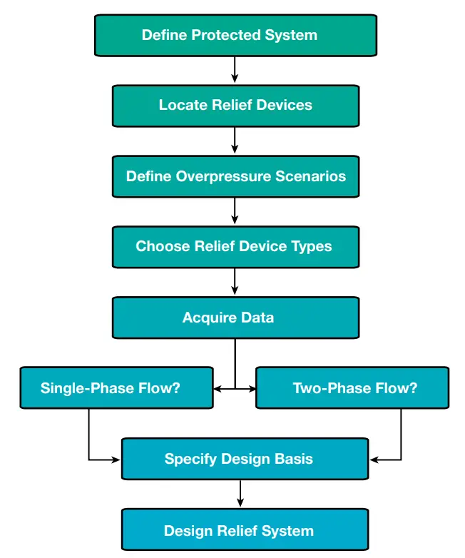
The sizing of the pressure relief valve is a complex method requiring a multi-step process as listed below:
- Defining the Protected System
- Locating the relief valve
- Defining the over-pressure condition
- Selecting the relief device
- Obtaining Data for Relief valve Sizing
- Determining the flow condition types
The above steps can be easily shown in the form of a flowchart as shown in Fig. 6.
Most major pressure relief valve manufacturers provide sizing software having the unlimited capability to accept wide variability of fluid properties and decide the right pressure relief valve. Some typical software for pressure relief valve sizing is developed by:
- Anderson Greenwood Crosby
- PRV2SIZE software Emerson Automation Solutions
- PRV2SIZE software Pentair Software
- VALVESTAR® by LESER Safety Valves
- SIZEMASTER – Relief System Sizing Software by Farris
- VALVIO by HEROSE
- Fluid-Flow
In absence of pressure relief valve sizing software or manufacturer’s standard tables, the effective orifice area can be manually calculated using the following equations:
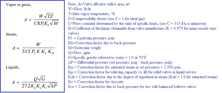
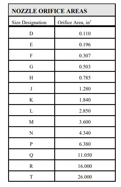
After getting the effective area, the Standard pressure relief valve orifice designation (size) is selected from the following table:
Pressure Relief Valve Symbols
Pressure relief valves are designated by special symbols as shown below:
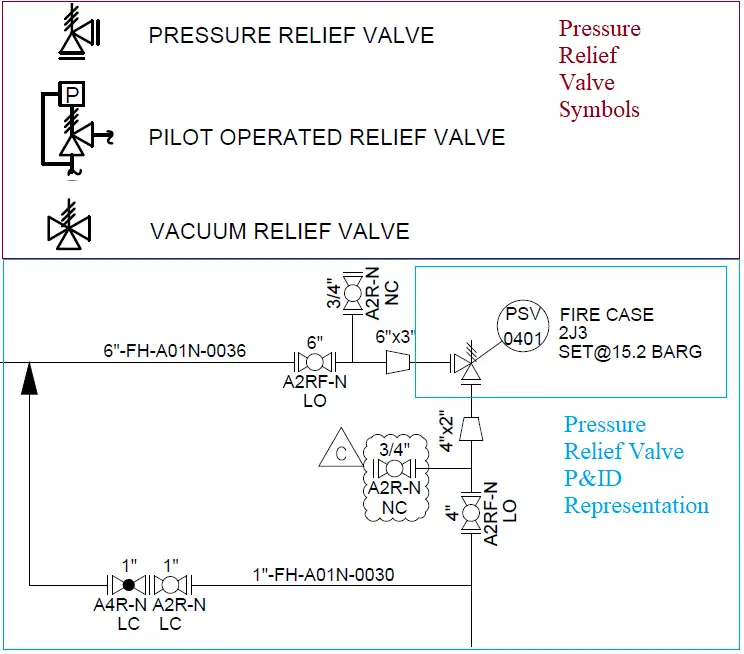
Fig. 9 also provides the P&ID representation of a typical Pressure Safety Valve. Set pressure and Orifice Designation is clearly mentioned in the P&ID, along with the identifier and symbol of the pressure relief valve.
Relief Valve Chattering
Chattering is the rapid opening and closing of a pressure relief valve at low flow rates. Under normal process conditions the vessel pressure is below the set pressure of the relief valve. As the pressure increases and exceeds the relief valve set pressure the valve opens. As soon as the valve opens there is flow resulting in a pressure drop between the vessel and the valve. If this pressure drop is large enough, the pressure at the relief valve can be low enough so that the relief valve closes. The flow stops, the pressure at the relief valve increases back to the vessel pressure because there is no flow to cause a pressure drop and the relief valve opens again.
- Spring relief devices require 25-30% of maximum flow capacity to maintain the valve seat in the open position
- Lower flows result in chattering, caused by rapid opening and closing of the valve disc
- This can lead to the destruction of the device and a dangerous situation
Chatter – Principal Causes
Valve Issues
- Oversized valve
- Valve handling widely differing rates
- Relief System Issues
- Excessive inlet pressure drop
- Excessive built-up backpressure
Oversized valves will partially lift at set pressure & then re-seat resulting in “chattering” of the disc which could damage the seat/disc surfaces and cause the relief valve to fail. It is good practice to install multiple relief valves for varying loads to minimize chattering on small discharges.
The general rule to prevent relief valve chattering: line pressure drop between equipment and inlet of RV during relief case must be <3% of RV set value.
Difference between a PSV and PRV
- A Pressure Relief Valve (PRV) opens gradually in relation to the pressure, on the other hand when the pressure reaches a certain value a Pressure Safety Valve or PSV opens suddenly to release the overpressure.
- PRV is normally used for liquid systems while PSV is for gaseous systems.
- The set point of PRV is usually 10% above the working pressure while the set pressure in PSV is generally 3% above the working limit.
Online Courses on Pressure Relief Valve
If you still have doubts, undertake the specially designed below-mentioned courses to improve your understanding of the subject:
- Pressure Safety Valve and other Safety Devices
- Introduction to Overpressure Protection & PSV
- Complete Pressure Safety Valve Training for Engineers
Few more useful Resources for you…
Pre-Commissioning and Commissioning Checklist for Flare Package
Flare systems: Major thrust points for stress analysis
Stress Analysis of PSV connected Piping Systems Using Caesar II
Articles related to Process Design
Piping Layout and Design Basics
Piping Stress Analysis Basics
Mechanical maintenance technician
Very well done. Gr8 job!
Conventional type PRV and Balanced Bellow Spring loaded PRV same or different type.
I hope, In conventional type PRV, back pressure should be in constant.Not in Variable.is it correct.
In PRV, bellows not used in conventional type PRV.am I correct.