
Piping systems be protected against over-pressuring by Pressure-relieving devices like pressure safety valves, and pressure relief valves, … by realizing extra pressure (popping up) according to the system operating philosophy.
Regarding variation of service fluid pressure and velocity between the upstream and downstream of PSV, during popping up PSV exert considerable reaction force over the system. During stress analysis of PSV-involved systems, we have to consider this reaction force.
Also according to Appendix II B31.1, Pressure loads acting on the safety valve installation are important from two main considerations. The first consideration is that the pressure acting on the walls of the safety valve installation can cause membrane stresses which could result in the rupture of the pressure-retaining parts. The second consideration is that the pressure effects associated with discharge can cause high loads acting on the system which creates bending moments throughout the piping system.
This article’s subject is an investigation of system allowable stress associated with PSV/PRV reaction force and PSV/PRV reaction force calculation is out of this writing goal. To learn about the PSV reaction force calculation and stress analysis philosophy kindly click here.
ASME B31.3 and Caesar II approach for occasional load and pressure-relieving load
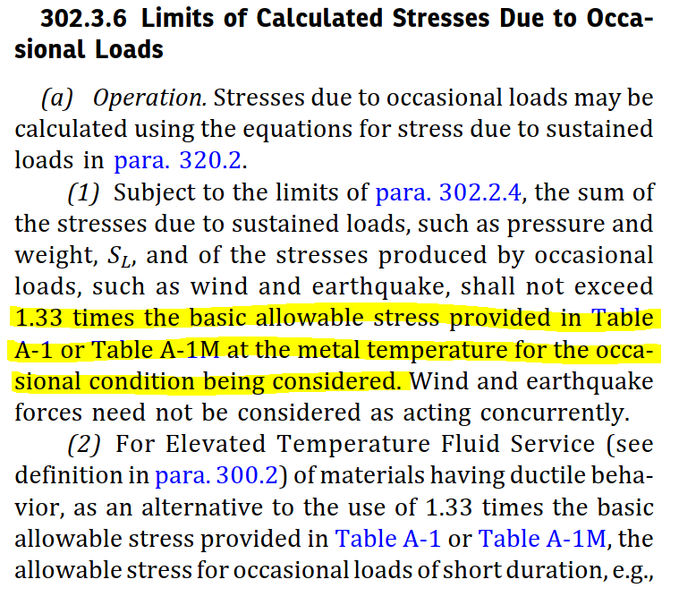
Some companies consider PSV/PRV reaction load like other occasional loads e.g. seismic loads/wind loads because it acts occasionally and according to clause 302.3.6 part (1) of ASME B31.3 (Refer to Fig. 1), use of 1.33 times the basic allowable stress provided in Table A-1/A-1M.
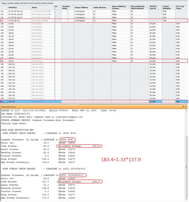
In the Caesar II equivalent static method, the PRV reaction force is entered in the input spreadsheet and proper load cases are prepared after adding those forces to simulate the behavior. But in the load cases, the OCC load Factor column is left blank and Caesar II by default use 1.33 as the occasional load factor similar to other occasional stress categories. Therefore, while calculating the allowable stress for PRV pop-up case, Caesar II software multiplies the allowable stress with 1.33 for the calculation of OCC allowable stress. Refer to Fig. 2 which shows a Caesar II snapshot for the same.
But note that factor 1.33 is for those occasional loads which occur into the piping design (operating) limitation but pressure reliving device duty is keeping away the system from over-pressurizing and does not operate since pressure is below design (set pressure) condition.
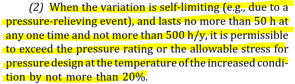
paragraph 302.2.4 part 2 Involves terms either or both of temperature and pressure variate from design condition. According to part (2) of 302.2.4 (B31.3), when the variation is self-limiting (e.g., due to a pressure-relieving event), and lasts no more than 50 h at any one time and not more than 500 h/y, it is permissible to exceed the pressure rating or the allowable stress for pressure design at the temperature of the increased condition by not more than 20%. Hence when Caesar II users leave the OCC load Factor blank for PSV/PRV load case, the relevant allowable load is calculated as about 11% more than the limiting of 302.2.4. Refer to Fig. 3 below.
So, as per my understanding, it can be concluded that occasional loads like wind and earthquake, maybe as much as 1.33 times the basic allowable stress but pressure relieving loads like PSV/PRV discharge reaction loads should be limited to an OCC factor of 1.2. It is, therefore, mandatory for Caesar II users to fill the OCC load Factor for PSV reaction forces as 1.2. Refer to Fig. 4 below.

I wish to know the inputs from other pipe stress engineers on the above subject on whether my understanding is right or I am missing somewhere. Kindly provide your input in the comments section.
Fine
Appreciated for sharing a very good info.
Thanks Again.
In my opinion, 20% in 302.2.4 is for pressure and temperature variation allowance, I think it means the PSV relief pressure can exceed the design pressure by 20% due to short duration. And I think we can consider PSV reaction force as OCC loads, you can check like ASME B31.1 104.8.3 Terms MB, it considers thrusts from relief/safety valve loads as occasional loads. So I think 1.33 times the basic allowable stress is ok for checking
In my opinion, 20% in para. 302.2.4 ASME B31.3 is for pressure and temperature variation allowance, I think it means PSV relief pressure can exceed 20% design pressure due to short duration. And I think 1.33 times the basic allowable stress is correct, we can consider PSV reaction force as occasional loads, you can check para. 104.8.2 ASME B31.1 terms MB, it considers thrusts from relief/safety valve loads as occasional loads.
For Conservative side, we can take 20% as we don’t know the pressure relieving event duration.