
Seismic Analysis of piping systems is performed to safeguard the piping systems from unforeseen earthquake events. During the initial design phase, based on earlier earthquake data available in codes and standards, piping systems and civil structures are designed to withstand piping movements during seismic events. The ASME B31 codes provide the allowable stresses for seismic analysis of piping systems. An equivalent static seismic analysis is the most preferred method, even though dynamic analysis is possible.
Piping Seismic Analysis Basis
The criteria for line selection for seismic analysis are normally mentioned in the ITB documents if the construction site falls under the seismic zone. If the same is not mentioned then the following lines can be considered:
- Lines with an outside diameter of 6” and larger.
- Transfer lines/Two-phase flow lines.
- Piping systems connected to Strain-sensitive equipment like Compressor, Turbine, and Pump.
- Heater and Cold box connected lines.
- Steam & flare header system in a pipe rack.
- Other lines are considered important as per the stress engineer’s decision.
Advantages of Seismic Analysis of Piping Systems
During a seismic or earthquake event, the piping system and components can lead to catastrophic failure if proper seismic analysis of piping systems is not performed during the design stage. So, earthquake analysis of piping systems must be performed while piping stress analysis if the plant falls under seismic zones as specified by codes. The advantages that a proper seismic analysis of the piping system offers are
- The system will be properly supported for earthquake events. So major system failure is prevented.
- The seismic analysis assists in identifying the limits and restrictions of the available design codes and standards.
- Civil structures will be designed accounting for piping seismic loads so robust design.
- Seismic design help piping engineers improve their ability to model the piping system behavior for a particular ground motion.
Stress Allowable Values for Piping Seismic Analysis
As per code ASME B31.3, the longitudinal stresses generated due to sustained and occasional loads should be within 1.33 times Sh (Basic allowable stress at hot temperature) value. So We have to add Sustained stress and occasional stress such that the scalar combination of the same remains within the limit specified by the code. Normally nozzle load checking is not required for seismic analysis. However few companies need the nozzle load checking at the seismic condition for static equipment. Sometimes the allowable nozzle load can be increased by 50% for checking in occasional cases. However, nozzle load checking is not required in the seismic case for rotating equipment. The following article will describe steps to perform the static method of seismic analysis in Caesar II.
Seismic Analysis of Piping System using Caesar II
The first step in the static seismic analysis is to collect the seismic coefficient. Sometimes the value of the seismic coefficient is provided directly and sometimes enough data is provided to calculate the same. The following equation (as per IS 1893) can be used to calculate the seismic co-efficient:
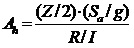
Here
- Spectral Acceleration Coefficient (Sa/g) = 2.5 (Examples are shown for the sake of a typical value calculation)
- Zone Factor (Z) = 0.16
- Response Reduction Factor (R) = 3
- Importance factor (I) = 1.75
- Horizontal Seismic Coefficient (Ah) = 0.12 (±X & ±Z Direction)
This co-efficient value needs to be entered in the Caesar spreadsheet as shown below:
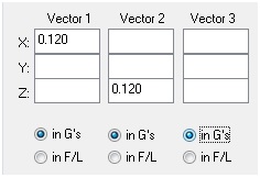
Normally the Y component is not entered. However, few clients may require the input of the same. in that case, follow the guidelines provided by them.
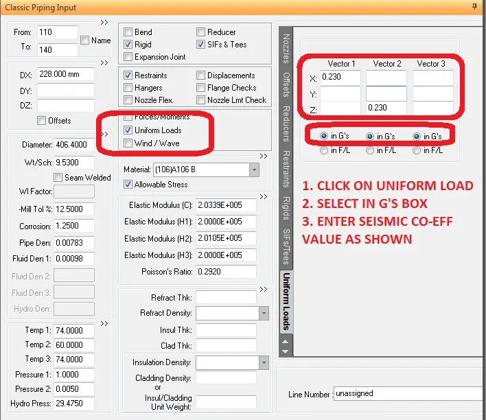
To perform seismic analysis open the Caesar II spreadsheet and click on uniform loads as shown in the below-mentioned figure.
Load Cases for Static Seismic Analysis
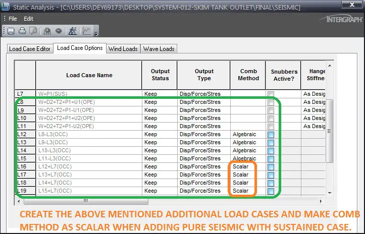
After that prepare the load cases for seismic analysis. The load cases normally prepared are shown in the figure attached below:
Checking Output of Seismic Analysis
Once you prepared the required load cases simply run the file and check the stresses for Code compliance as mentioned below:
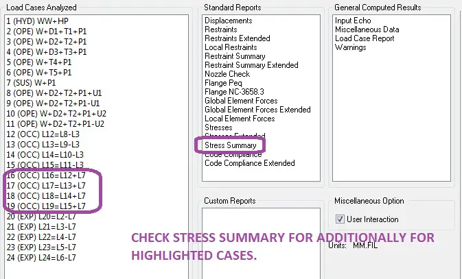
Check the restraint summary for load cases L8 to L11 in the above-mentioned figure and check stresses for load cases L16 to L19.
The above method explained is the equivalent static method of seismic analysis for piping systems. The earthquake analysis can also be performed using the dynamic spectrum method in which a dynamic spectrum must be generated for analysis.
sir,
here i saw in load cases Displacement “D2” has mentioned with uniform load “U”(SEISMIC LOAD) in operating cases. My question is- Is it necessary to mention displacement term in load cases with “U” ??
what kind of displacement D2,D1 represent in above load cases??
thanks in advance for your reply
Here the displacements D1 and D2 may be thermal displacements. It could be due to Equipment growth. Or often people use displacements of headers at branch connections to skip modelling of long headers.
How do I find Horizontal Seismic Coefficient as per Standard ASCE 7 for Piping? What formula shall be used and what inputs I need from client so that I can analyse the system in CAESAR.
Looking Forward
How can I calculate sa/g value for my project?
Refer IS1893 Part-1 Cl.6.4.5
Thank you for sharing about seismic…. I have been reading some blogs that gives me more knowledge about it. I must say this is one of the best among them. You have done a great research for I feel, thanks for sharing.
why SCALAR operating when combining pure occassional with sustain case?
How do your results from the statically applied seismic load compare to the CII spectrum analysis, controlling for all the same seismic variables? Is it more or less conservative from a pipe stress standpoint?
Dear Sir,
My organisation is looking for SEISMIC ANALYSIS of underground cross country natural gas pipeline . We have CAESAR II license with us. I want to talk to you regarding this issue. Can I have your contact ?
Thank you for the article. I would like to know a code or reference where the Response Reduction Factor (R) for piping be defined. In the article the value for this factor is 3 but I can’t find the reference in the IS 1893 Code. Could you please help me with this information? Thank you very much in advance. Regards.
We are doing 48″ cross country pipeline as per the code ASME B31.4.
While taking the Dynamic run in to CAESAR-II EARTHQUAKE SPECTRUM, output shows 0-Zero calculated stress values vs. 0 allowables.
Kindly share with us an expert openion.
Thanks,
Can you share Caesar II to me?
Thank you for the article. I have a quiestion about”However, nozzle load checking is not required at the seismic case for rotating equipment. “. Why is it? Is there a code or standard about that?
Thank you so much
i have a question.
Lines with an outside diameter of 6” and larger.
Why not small NPS?
Please follow your stress analysis design basis criteria. That values are some typical guidelines.