
Axial Stress from Pressure Load, Axial Force and Torsion Moment
This issue leads to serious under-estimation sustained and expansion stresses in pipes and fittings in ASME B31.1-2018, ASME B31.4-2016, ASME B31.5-2016, ASME B31.8-2016, EN 13480-2017, ISO 14692, and some other codes.
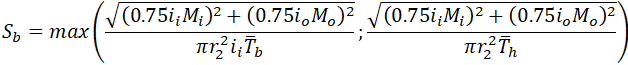
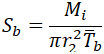
For example, let’s take ASME B31.1-2018 code that requires using the following equation for stress from sustained loads (104.8.1):
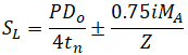
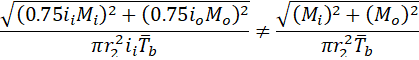
The first problem is not so serious for above ground piping. This equation is suitable only for totally unrestrained pipes, but it is easy to use in manual calculations, and it is always conservative. For more information please refer to the article What is Restrained and Unrestrained Pipes. Also in software, the more accurate equation is recommended to use for axial stress 102.3.2 a (3):
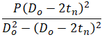
Instead of a simplified equation, that is easier for manual calculations

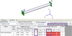
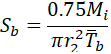
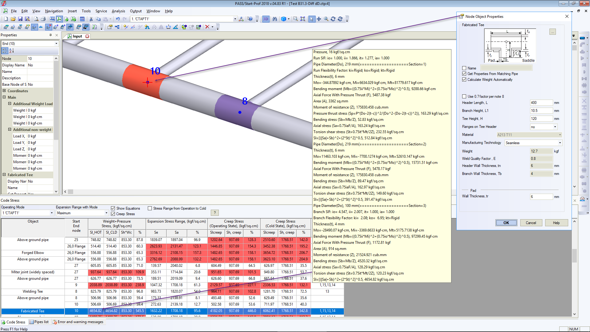
The second and most serious problem is with the formula (104.8.1). It doesn’t take into account axial force in the pipe. Sometimes, the axial force from sustained loads can be so huge, that axial stress becomes greater than allowable. Engineers can easily overlook this problem when using pipe stress analysis software for big models. For example, it could be very tall vertical pipes or heavy valves on the vertical pipes. The code sustained stress for this model is almost zero (see “Sl” stress in the screenshot below). But real sustained stress is greater than allowable (see “Sl*” stress in the screenshot below).
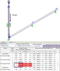
The same problem with the expansion stress equation (104.8.3), it doesn’t include axial force too
For example for totally restrained pipe code expansion stress range will be zero (see “Se” stress in the screenshot below). But real stress range is greater than allowable (see “Se*” stress in the screenshot below).
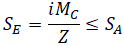
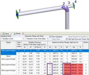
Sometimes even experienced piping designers can make a mistake and create a wrong design. For example in the piping system below, the 1-2 pipe is restrained by trunnion 2-4. Code stress range is zero, but if we choose the option to include axial force the stress range is greater than allowable!
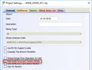
To protect users from such mistakes we add the special option in PASS/Start-Prof software that allows taking into account stress from the axial force and torsion moment for sustained stress and for expansion stress range. Users can simultaneously see official code stresses (Sl, Se) and modified stress (Sl*, Se*) in the same table. It also automatically solves the first described problem with axial stress from pressure load for restrained, totally unrestrained, and middle behavior systems. Axial stress from pressure load (Sl*) will also be more accurate. This option may be activated using the “Add axial force and torsion stress” checkbox in Project Settings.
For modified stresses PASS/Start-Prof software use the equations similar to ASME B31.3 code:
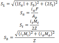
We recommend always switching this option on!
Effective Tee Branch Section Modulus Issue in ASME B31.3-2016
This issue led to serious under-estimation of sustained and occasional bending stresses at reducing intersections.
ASME B31.1-2018 code requires to calculate the bending stress from thermal expansion for reducing tee branch by equation (all symbols are taken as per ASME B31.3-2016 code for better understanding):


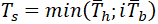
Z is section modulus, where effective branch wall thickness is

is the thickness of pipe matching branch,

is the thickness of the pipe matching run of tee or header.
What is the effective branch wall thickness? The answer is given in L.C. Peng’s “Pipe Stress Engineering” book, 4.5.1. The idea is the following. Bending stresses must be checked in two potential locations of failure:
- In branch and header pipes junction, zone 1
- in branch pipe next to the junction, zone 2
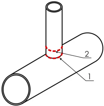
The failure will happen in zone 1 if the stress intensification factor is high. But if the stress intensification factor is not significant, the failure will happen in zone 2. The code should check the bending stress in both locations.
ASME B31.1-2018 use simplified equation 104.8.3, 104.8.4C:
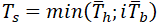
Where effective branch wall thickness is
For sustained stress equations for 1 and 2 zones should be:
The simplified equation in ASME B31.1-2018 104.8.1, 104.8.4
Now let’s check ASME B31.3-2016 code. As it uses two stress intensification factors (in-plane and out-plane), the equation for bending stress in locations 1 and 2 should be:
But ASME B31.3-2016 code offers for reducing tee bending stress from sustained loads the equation 23b2
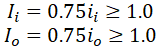
Sustained in-plane and out-plane SIFs:
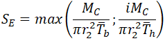
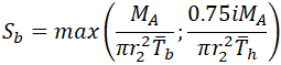
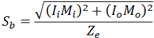
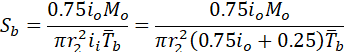
Effective section modulus of branch
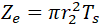
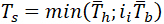
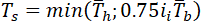
Effective wall thickness is determined according to 319.4.4 (c)
If we convert these equations back to the stresses in 1 and 2 locations, we will have
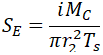
For location 2 stresses become incorrect:
Let’s assume that Mo=0, in this case, we get underestimated by 25% bending stress in the branch pipe
Instead of correct stress value
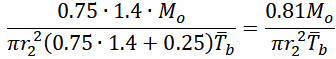
If we take Mi=0, we get bending stress in the branch pipe
If we assume that io=1.4, then we get bending stress underestimated by 19%
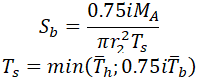
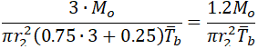
To partially fix this problem we should change the equation 23b2 for effective wall thickness in 320.2 to
But in this case, the out-of-plane bending stress in branch connection will be overestimated. If we assume that io=3.0 the out-of-plane bending stress in branch pipe will be overestimated 25%:
To fix this problem we should correct the bending stress equation in 320.2 to
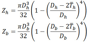
Zh – Header section modulus, Zb – Branch section modulus.
Unfortunately, these corrections can’t be made in the software. The ASME B31.3 code revision needed.
Fortunately, a new code ASME B31J-2017 has been released. Using this code we can bypass this problem. We recommend activating the “ASME B31J” option in PASS/Start-Prof software.
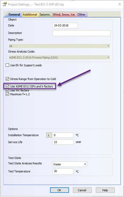
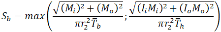
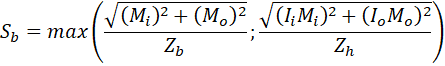
If this option is activated, the accurate section modulus will be used for header and branch pipes:
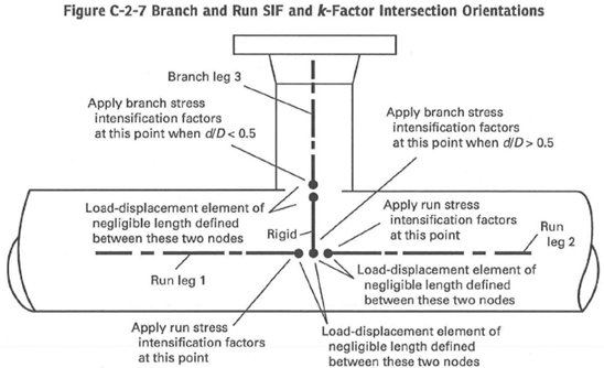
Also if “ASME B31J” option is activated then all tees are automatically modeled with simultaneous use of run and branch springs with flexibilities and stress intensification factors calculated according to ASME B31J code requirement:
Start-Prof software allows activating the “ASME B31J” option for all ASME B31 codes and EN 13480! If some of k-factor becomes less than 1.0 Start-Prof assumes this spring as rigid:
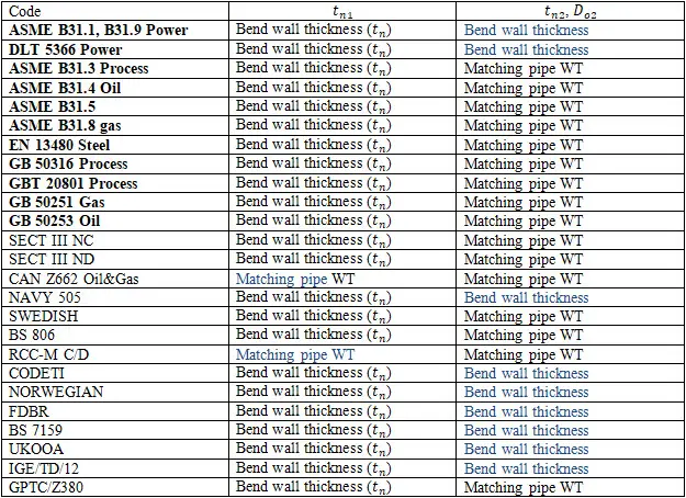
Real Bend Wall Thickness is Greater than the Matching Pipe Wall Thickness
This is a very serious issue. It leads to an underestimated pump, nozzle, and support loads and stresses calculated by ASME B31 codes!
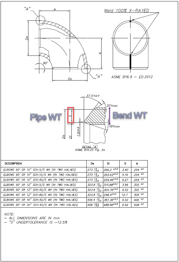
ASME B16.9 and all ASME B31 codes don’t regulate the bend, tee, and reducer wall thickness. Only the pipe wall thickness is regulated. So many people think that the elbows and other fittings have the same or almost the same wall thickness as the matching pipe. But in most cases, the real bend, tee, reducer body wall thickness is greater than matching pipe wall thickness with the same Schedule.
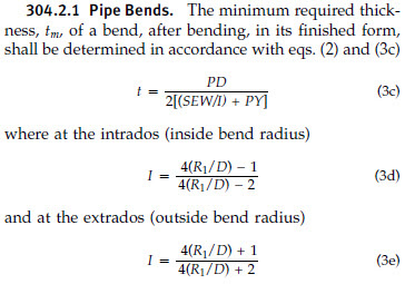
For elbows, the real wall thickness can be 10%-40% greater than the matching pipe. Because bends must have greater wall thickness to hold the same pressure as the connected straight pipe (see 304.2.1 3d).
Manufacturers usually produce the bends with a greater wall thickness than matching pipe, but we can get real bend wall thickness only after contacting the manufacturer or even measure it after delivery.
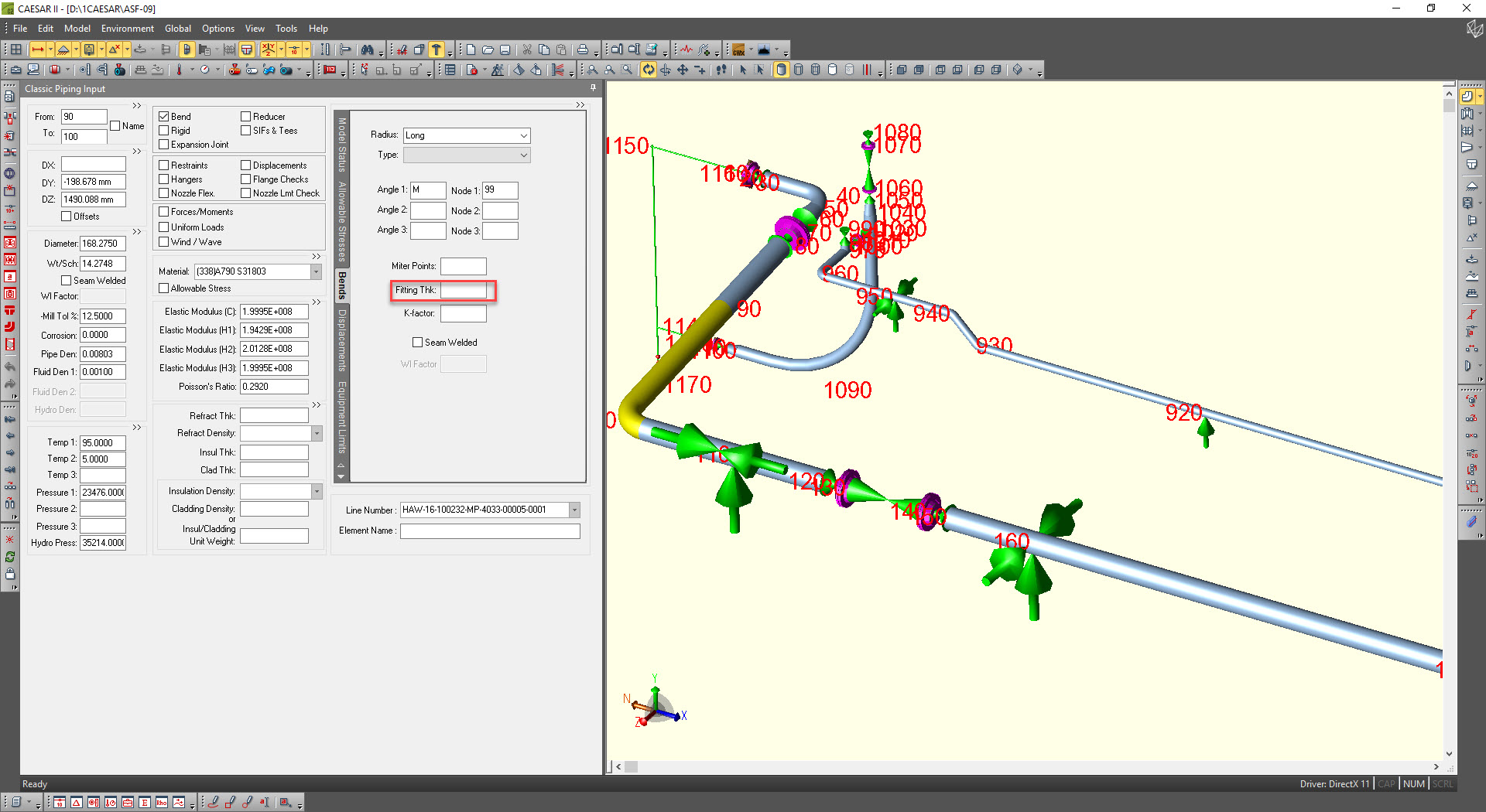
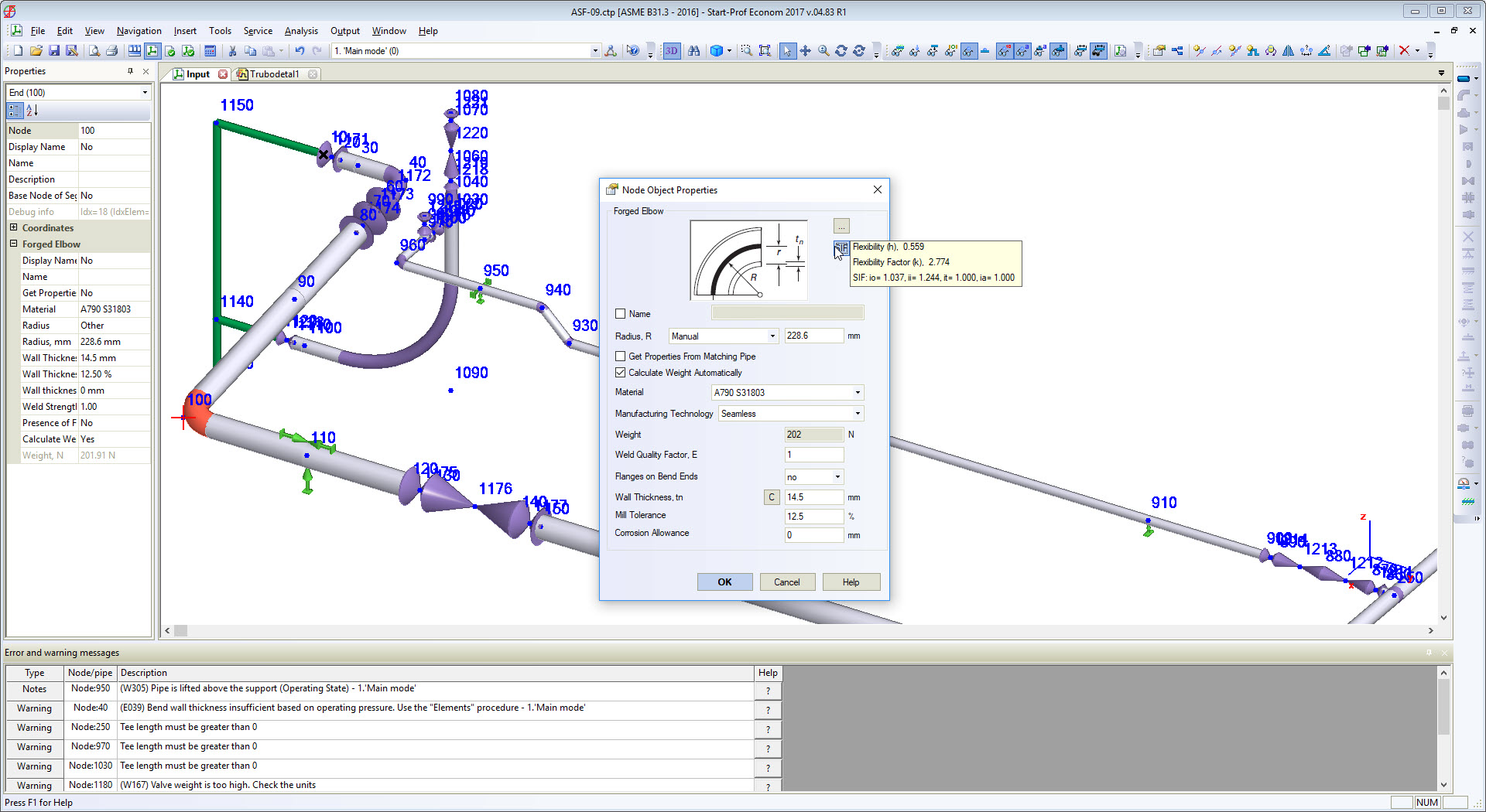
Piping designers usually know nothing about it. And piping stress engineers usually use the pipe wall thickness for elbows when using piping stress analysis software. Leaving the “Fitting Thk” field blank makes software thinking that elbow has the same wall thickness as a connected pipe element. This is a serious mistake!
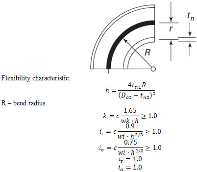
According to the ASME B31 and other ASME B31-based codes bend flexibility factor depends on real bend wall thickness, not on matching pipe wall thickness.
The greater bend wall thickness, the greater is bend stiffness (k-factors) and greater are loads on rotating equipment, nozzles, supports and expansion stresses in piping system.
This problem quite often comes to light when Russian companies try to check the design made according to ASME B31 codes for the Russian market. While rechecking the stress analysis using PASS/START-PROF software according to GOST codes a lot of error messages appear. They say that the wall thickness of the elbows is lower than the minimum required one to hold the pressure because it is usually left blank in CAESAR II and software takes fitting thickness equal to connected pipe WT in the piping stress model. When the real elbow wall thickness entered and model recalculated, the nozzle loads and stresses become much greater than it was calculated in CAESAR II and other software! That’s because the elbow flexibility k-factors used during analysis was incorrect.
But in real practice counterparts usually can’t provide the real bend body WT. They just don’t have this information!
We received different answers to the direct question – “what will be the real wall thickness throughout the whole bend body?”
- Some manufacturers do not answer at all;
- Others say it’s a trade secret (?!);
- Some manufacturers replied that the edge will be 100% consistent with that ordered according to ASME (according to schedule), but the thickness of the wall at the bend may even be 40% greater!
Only after we receive the ordered fittings (bends, reducers, and tees) from the factory, only at this time we can measure and find out what are the real wall thicknesses. The stress analysis model should be changed, nozzle loads become greater. The design should be changed to add more flexibility and reduce nozzle loads and sometimes expansion stresses. And all of this should be done after the design job by our contractors was formally “finished”. Amazing!
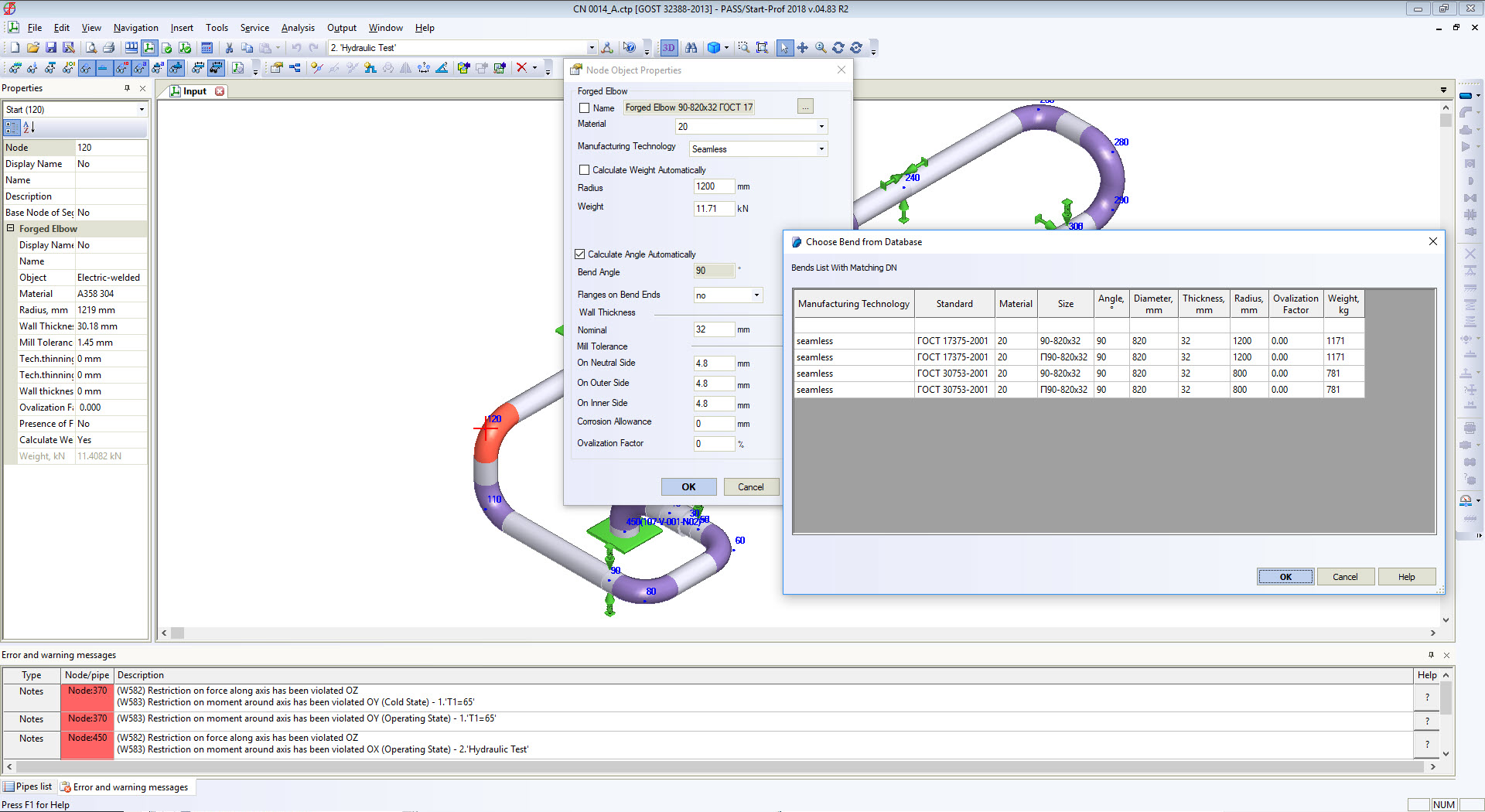
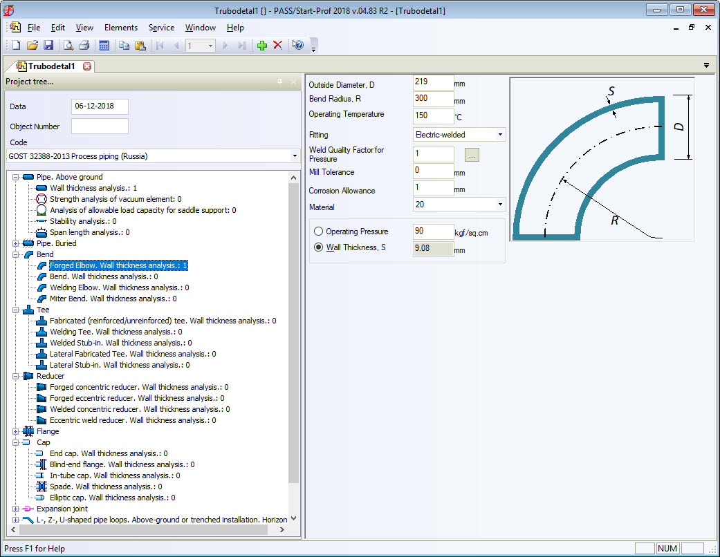
For example, Russian standards, which are completely different from ASME B16.9 for bends, tees, and reducers, always provide the real body wall thickness for each fitting. Manufacturers follow the standards. Every piping stress engineer knows the real body wall thickness of bends and other fittings and specifies it in START-PROF while performing piping stress analysis. Also, all the bend properties can be taken from the fitting database (see screenshot below).
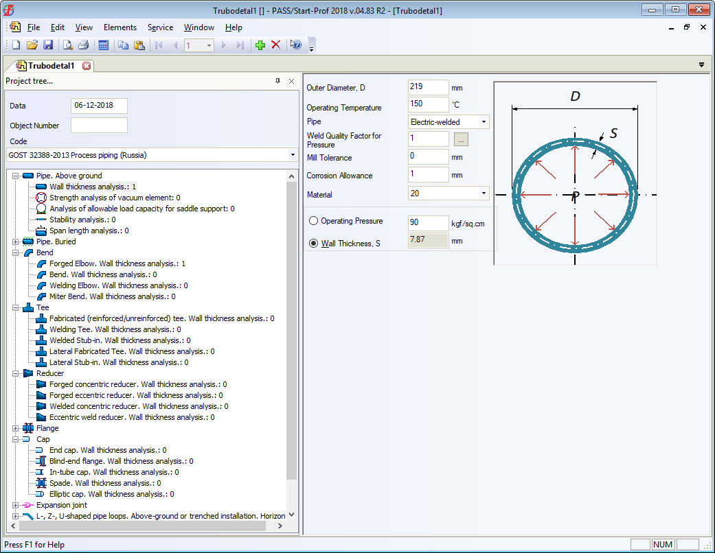
All RD, GOST, and SNiP stress analysis codes (power, process, oil & gas main pipelines, etc.) provide detailed wall thickness calculation procedure for all fittings including bends, tees, and reducers. On screenshots below, you can see that the calculated bend wall thickness is always greater than pipe wall thickness for the same pressure load.
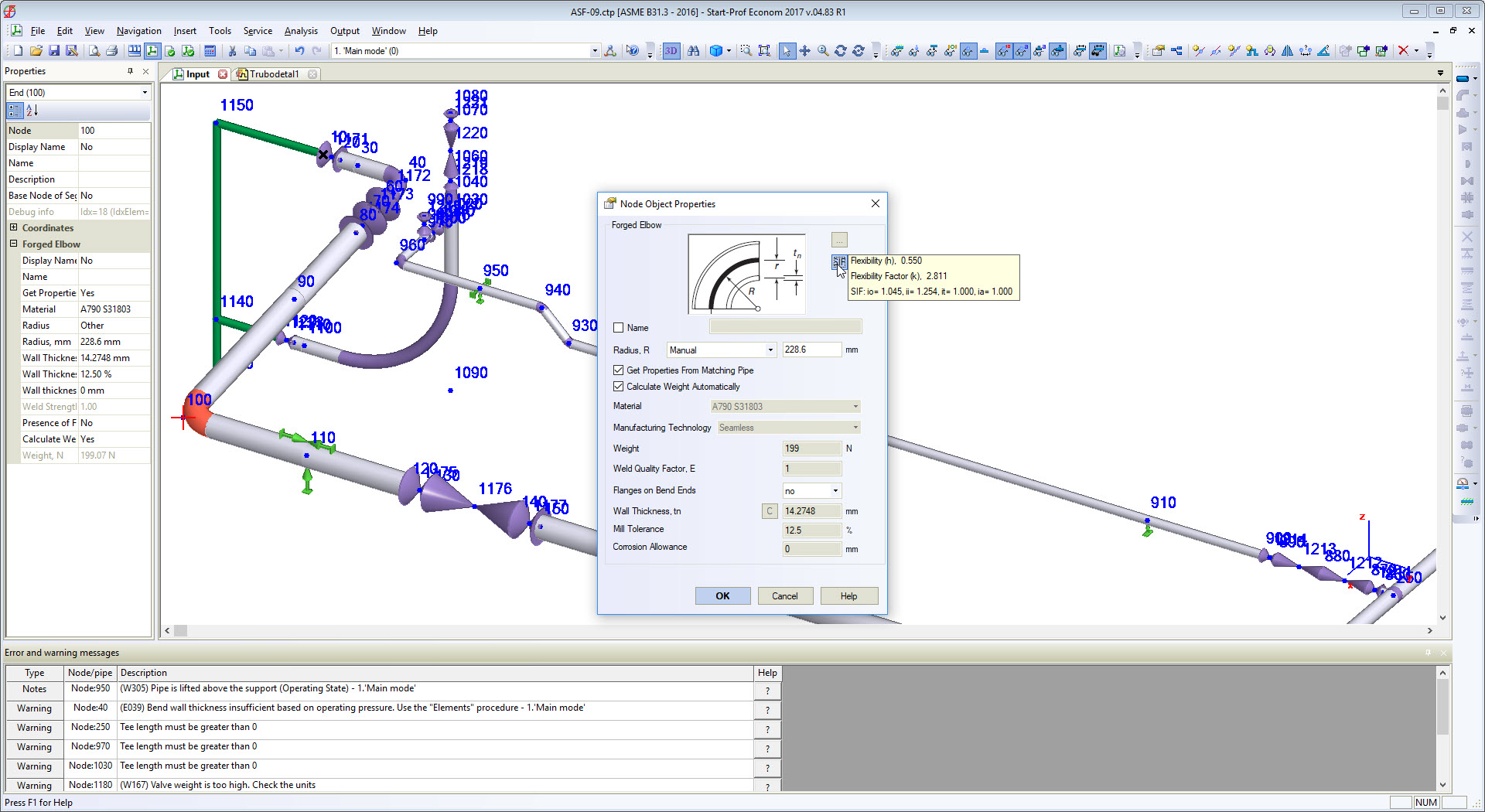
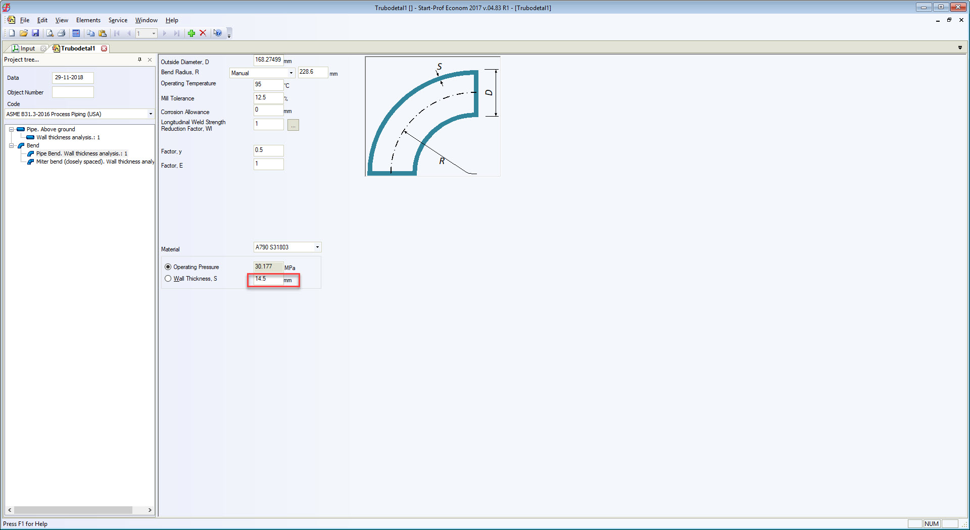
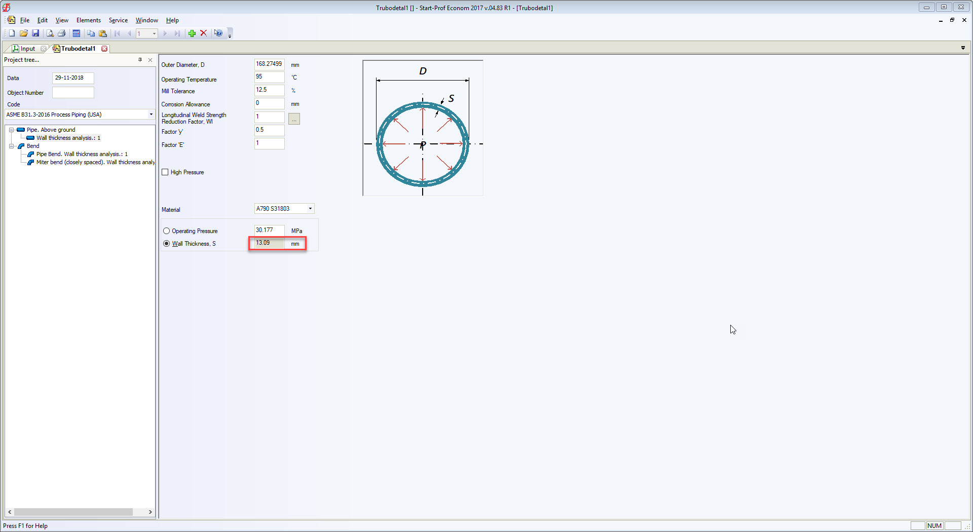
The real bend body wall thickness should be used in piping stress analysis instead of matching pipe wall thickness. To solve this problem we added the special feature in PASS/START-PROF software that allows calculating the approximate “real” bend wall thickness on-the-fly according to ASME B31.3 304.2.1 and the same requirements in other ASME B31 and EN 13480 codes. Just push the button “C” near the “Wall Thickness” field and it will be calculated according to the code requirements.
Conclusion
- Bend, tee and reducer wall thickness should be regulated by ASME B31 codes and provided in ASME B16.9 code. Manufacturers should produce bends with body wall thickness according to the code requirements.
- Until the first problem is solved, the manufacturers should provide bend wall thickness in their catalogs. It will allow designers and piping stress engineers to use the real WT in the pipe stress model and to get accurate nozzle loads and expansion stresses.
- There should be a special remark in ASME B31 codes that explains how to calculate flexibility k-factors for the elbows if the real body wall thickness is unknown.
- If the elbow wall thickness is unknown, then piping stress engineers should use WT calculated by ASME B31 code equations for bend or use pipe wall thickness multiplied by 1.4 factor. This will provide more conservative design, and after the real bend, wall, thicknesses will become available (can be measured) the changes in piping design will not be as critical, as now.
To listen directly from the author and learn refer to the following embedded video: