
Prior to commissioning, it is essential to thoroughly clean the internal surfaces of pipes. This cleaning process, known as steam blowing, is used to remove rust, dust, scales, and debris. If this procedure is not executed properly, it can lead to significant damage or a shortened lifespan of critical components such as steam traps and control valves.
Steam blowing is a critical process used primarily in the commissioning and maintenance of steam systems. It involves the use of high-pressure steam to clear out impurities and debris from the pipes of a steam generation system, ensuring the system operates efficiently and safely. In this blog post, we’ll delve into the fundamentals of steam blowing, its purpose, procedure, benefits, and key considerations.
What is Steam Blowing?
Steam blowing, also known as steam flushing, is a method employed to clean the internal surfaces of steam pipelines and equipment. It is most commonly used in power plants, petrochemical facilities, and other industrial applications where steam systems are prevalent. The primary goal of steam blowing is to remove any residual debris, welding slag, mill scale, or other contaminants that might obstruct the flow of steam or cause damage to the system.
Steam blowing is one of the initial cleaning operations before starting any power plant or steam lines. Steam blowing of MS lines, CRH, HRH, SH, RH, HP, & LP bypass pipelines of the turbine is carried out in order to remove welding slag, weld bead deposits, loose foreign materials, iron pieces, rust, etc. from the system, generated during manufacturing, transportation, & erection prior to turbine operation. The cleaning is accomplished by subjecting the piping systems to heating, blowing steam, and cooling cycles in sufficient number and duration until clean steam is obtained.
Why is Steam Blowing Necessary?
During the construction or maintenance of steam systems, particles, and debris can accumulate inside the pipelines. These contaminants can originate from welding processes, pipe manufacturing, and even the installation phase. If not removed, these particles can lead to:
- Reduced Efficiency: Blockages or restrictions in the pipes can reduce the efficiency of steam flow, leading to higher energy consumption and operational costs.
- Equipment Damage: Debris can cause erosion, corrosion, and damage to critical components such as turbines, valves, and heat exchangers.
- Safety Risks: Inadequate cleaning can increase the risk of operational failures, which may lead to safety hazards, including potential explosions or leaks.
Working Principle of Steam Blowing
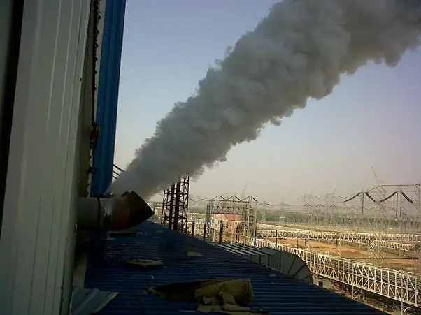
The working principle of steam blowing involves using high-pressure steam to clean and clear debris from pipelines and equipment. The process begins with the generation of steam at high pressure and temperature from a boiler or steam generator. This steam is then directed into the pipeline or system through specialized blow-off connections. The high-velocity steam creates dynamic pressure within the pipes, which effectively dislodges and carries away contaminants such as rust, dust, scales, and welding debris.
As the steam flows through the system, it sweeps out impurities by exerting significant force, thereby ensuring that the internal surfaces of the pipes are thoroughly cleaned. This process not only removes blockages that could impede the flow of steam but also helps prevent potential damage to critical components like valves and turbines. Proper monitoring and control of steam pressure and flow are essential to ensure the effectiveness of the cleaning and to maintain safety throughout the operation.
The effect of Steam Blowing depends on the following factors:
- Thermal shock
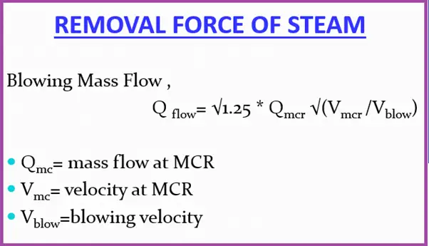
- Removal force of steam
- Cleaning force of steam
Cleaning Force Ratio or CFR of Steam Blowing
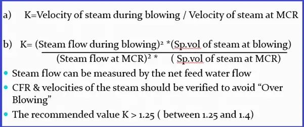
The necessity to create in the system, a steam velocity greater than that is possible at MCR condition is obvious. These two velocities are expressed as a ratio “Cleaning factor” or “ Distribution factor” or “Cleaning Force Ratio” denoted by “X” or “K”.
CFR (Cleaning Force Ratio) is also known as Cleaning Factor or CF. CFR is an industry-accepted factor that determines the required dynamic pressure. CFR in steam blowing can be defined as the ratio of required dynamic pressure for cleaning to maximum dynamic pressure experienced during system operation.
Cleaning Force required (CFR) or distribution Factor
Preconditioning for Steam Blowing
- Chemical cleaning should be completed.
- SH’s primary and secondary de-superheater piping and RH’s emergency de-superheater piping ready for operation
- All permanent piping & temporary piping insulated and supports/hangers are released with a cold setting
- The silencer should be connected at a temporary pipe exit
- Soot blowing for APH should be available
- Makeup for the deaerator made ready
- Motor-Driven BFP with all controls made ready
- Hydraulic test of the following lines completed:
- Feed Lines
- MS, HRH, CRH Lines
- MS to Aux. PRDS Line
- All other auxiliary lines identified for steam-blowing
- The sampling system made ready
- Boiler auxiliaries proved serviceable and ready after a pilot operation like:
- Fuel oil system
- Compressors & Atomizing steam system
- Start-up system ( for the continuous system)
- Coal Mill system (for the continuous system)
- CHP readiness
- Economizer hopper and bottom ash hopper and its evacuation system (for the continuous system)
- All safety valve discs installed after removing the hydro-static plugin drum(sub-critical), superheaters, and reheaters
- Adequate communication between the control room, boiler, and TG are ensured.
- Flow nozzle, control valves, and NRV flaps wherever applicable should be not erected before steam blowing and suitable spool pieces are erected. Strainers in the path should be removed.
- Required number of Target Plates and holders made available
Chemical Cleaning Process
- Boiler Front System Alkaline Flushing
- Mass Flushing
- Hot water Rinsing
- Alkaline Flushing
- Hot DM water Rinsing
Main Boiler System Acid Cleaning
- Super Heater Filling
- Mass Flushing
- Alkaline Flushing
- Hot DM water Rinsing
- Acid Cleaning
- Passivation
- ACID CLEANING ( BY CITRIC ACID METHOD )will be done by the circulation method for the effectiveness of the cleaning process.
- Acid cleaning will be followed by PASSIVATION so that the uniform protective coating of GAMMA FERRIC OXIDE is formed on the metal surface and corrosion/oxidation damage to the metal surface is prevented and continues during normal operation by dosing oxygen. The gamma ferric Oxide formed by using the chemical 1-2 % sodium Nitrite(NaNO2)
Steam Blowing Procedures Techniques
Normally, two methods are historically used for steam-blowing
- PUFFING METHOD
- PURGING METHOD / CONTINUOUS BLOW METHOD
PUFFING Method of Steam Blowing
To give a thermal shock to the contour being purged, to dislodge the scale, etc.
Procedure: Raise the boiler pressure to a pre-determined value (40-60 kg/cm2), shut off firing, and at the same time open the quick opening valve(EOTV), thus allowing the steam to escape to atm. with high velocity carrying with it the loose debris.
Precautions during the puffing method
The Pressure drop allowed in the drum is limited to the corresponding saturation temp. change of 40 OC.
Scheme of puffing method
Steam blowing done in stages
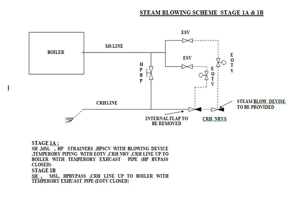
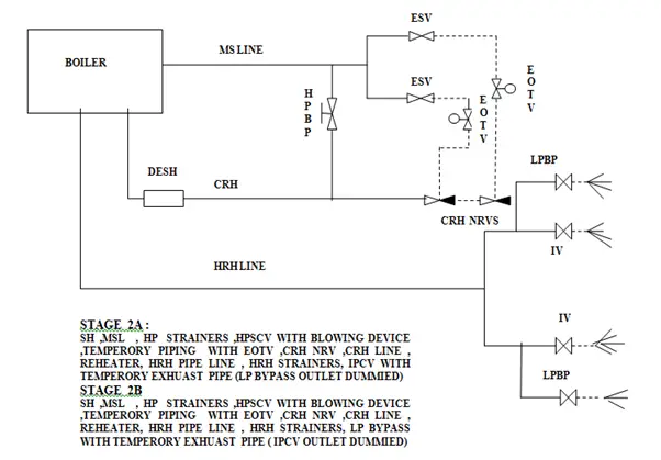
Stage-1(a):
- SH, MSL, ESV, temporary lines from ESV to EOTV, EOTV to CRH line, CRH lines up to boiler end with the temporary exhaust pipe.
- Tap-off lines from CRH to deaerator, auxiliary PRDS, HP heater 6a & 6b, gland sealing, etc. shall remain closed/isolated.
- Stage 1a endpoint will be concluded by observing the indents on the target plate.
Stage- 1(b):
- SH, MSL, HP bypass interconnection, hand-operated valve mounted in place of HP bypass valve, and CRH lines up to Boiler end with temporary exhaust piping.
- In this stage, 6 to 8 blows will be given through HP bypass lines to ensure the cleanliness of the limb.
- The boiler MS stop valve will be used for stage 1b. EOTV will be kept closed. Manually Operated Isolation Valves in HP bypass lines will be kept open fully.
Stage-2(a):
- 1a plus reheater, HRH lines, Interceptor Valve, and temporary pipe.
- CRH line along with the attemperator shall be welded with a reheater before the start of stage 2a. LP bypass lines shall be blanked during stage 2a. Stage 2a endpoint will be concluded by observing the indents on target plates
Stage- 2(b):
- 2a up to IV + LP bypass lines with the temporary exhaust pipe.
- Stage 2b blowing will be a parallel blow in paths 2a & 2b. LP Bypass blanks shall be removed for stage 2b. 4 blows will be given through the L.P. Bypass line to ensure the cleanliness of the limbs
Stage-3:
Auxiliary Steam Lines covered in steam blowing are listed below.
- 3a) Main steam line to Aux PRDS
- 3b) CRH to Deaerator
- 3c) CRH to HPH-6.
All auxiliary steam lines will be steam blown by the continuous blowing method
Stage-4:
The following Aux steam lines, connected to the deaerator are steam blown using auxiliary steam from the Auxiliary PRDS header.
- 4a)PRDS to Deaerator.
- 4b)Extraction 4 to
- 4c) PRDS to Gland steam header
Continuous Steam Blowing Procedure
- The initial procedure is the same as the puffing method except:
- Continuous firing till the completion of steam blowing. No need to shut off the firing during blowing.
- Maintain constant pressure during the blow
Recommended blowing parameters for continuous steam blowing
- Dynamic steam pressure = 3.5 MPa
- MS temp = 420(not to exceed)
- HRH temp = 480( not to exceed)
- Steam flow = 845 TPH
- Corresponding Drum pr. = 40 Ksc
- Furnace load ≈ 39%
Method of Continuous Steam blowing
- Set the Temporary purging valve, by-pass valve, drain valve, and granulating device behind the temporary pipes
- Check the tightness, support, and expansion of the temporary system
- Section by section rinse of condensate water piping, feedwater piping, and boiler through the start-up system to the CW system
- Circulation begins when Fe+ in the water of the main feedwater pipe and separator outlet will be less than 100 ppm.
- Maintain the circulation flow or start-up flow at a minimum set value
- Start oil firing and raise the temp and press. according to the cold start-up.
- rise rate of water wall = less than 2OC / min
- rise rate of main steam = 4 ~ 5 OC / min
- Before MS press reaches 1.0 Mpa, open the bypass valve of the temporary purging valve to warm the piping with all water drain valves of the system open.
-The blowing system is divided into two parts
- A) Preliminary Steam Blowing
- B) Final Steam Blowing
Preliminary Cleaning
PURPOSE-
- Primary cleaning out sundries and bulky grain deposited in the RH and main steam system
- To ensure the fastness of supports and hangers with proper expansion
- Know well about the operation property of the oil-burning system, condensate water, and feed water systems
Preliminary Steam Blowing Procedure
- Start the oil firing with max. rating of 15%
- Control the gas temperature at the furnace outlet below 500 OC (max.538OC )
- Raise the SH outlet press to 1.6 – 1.8 Mpa with a steam temperature of around 350 OC.
- Open the temporary purging valve for 15-20 min to blow in the MS system
- Maintain K around 0.5.
- SH & RH desuperheater water system also cleaned
Final Steam Blowing Procedure
- The main steam and reheated steam system are purged in series
- Start 2-3 coal mills when the oil burner hits the rated firing rate of 15%
- Increase the SH outlet press. to 3.5 Mpa.
- Maintain the MS temp < 420 OC.
- Keep HRH steam temp around 480 OC.
- When the steam line blowing parameter reaches, open the temporary purging valve gradually and increase the fuel and feed water volume to sustain parameter stability.
- Establish the MS flow around 40% of the MCR (max.- 50%)
- Ensure CFR (K) should be 1.25 to 1.3 for MS and 1.05 to 1.1 for reheated steam
- Blow under this operating condition for 20 to 30 min
- Gradually reduce coal firing and close the purge valve at 0.5MPa.
- Remove the target plate and check it
- By estimation, the target may satisfy the requirements after 15 to 20 times in-series purging
- When the steam line temp is above the sat. temp of MS press, close all drains and Open the boiler MSSV fully.
- Maintain the press. through controlled firing
- Insert a reference target
- Check the CFR
- Allow running for 30-60 min
Target Plate in Steam Blowing
- Generally Stainless steel panel
- Target plate set at the first, sixth, ninth, and twelfth purging, thereafter, set a target for each purging until purging results qualified.
- Width about 8% of the steam vent tube inner diameter (ID) and length equal to the ID
- Brinell hardness < 90
- Steam velocity – 258 m/sec
- Target plates are to be introduced just before steam blowing/light up—to be removed soon after blowing is completed.
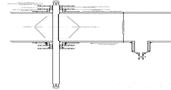
Online Target Plate Change Arrangement
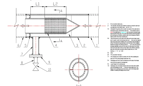
Debris Filter
Steam Blowing Completion Criteria
- At least 2 continuous target plates should not have ORIFICE GRANULARITY on the target and shall be no larger than 0.8 mm.
- CFR should be 1.25 to 1.4 of an orifice, granularity shall not surpass 08 nos.
Determining Cleanliness After Steam Blowing
To assess the cleanliness of a piping system after steam blowing, “target plates” are used. These plates, typically made of aluminum or copper, help gauge the effectiveness of the cleaning process. The evaluation involves three key steps:
- Placement and Impact Assessment: Position target plates at the outlet points of the main piping system during the steam blowing operation. Assess the impact on these plates to evaluate the cleaning action.
- Evaluation of Results: The cleaning process is deemed effective if two consecutive target plates show fewer than two pits per square inch, with each pit having a maximum diameter of 0.3 mm.
- Reinstallation and Recommissioning: After steam blowing, reinstall any removed steam traps and other equipment. Following these steps, the piping system can be reheated and recharged for operational use according to its intended purpose.
Advantages of Steam Blowing
- Required less time for completion of the total process
- Less time is required to normalize the system for final light-up to synchronization
- This reduces the reactionary forces on the temporary pipes
- Stresses on the boiler system are lower
Comparison between Puffing & Continuous Method of Steam Blowing
| PUFFING METHOD | CONTINUOUS METHOD |
| More time is required for complete steam blowing due to stage-wise blowing(8-10 days) More time is required for stage-wise temporary pipe erection and shifting of the blowing device No mill required Quality of cleanliness is better than a continuous process Thermal shock is the driving force behind cleaning More thermal stress on tube material and sudden loading on supports Repeated light-up and shutdown There is a time gap between the blows to make up DM water System normalization time after steam blowing is more Silencer use is optional | Less time required for completion (3-4 days) Less time is required as only valves are to be opened for different systems Minimum 02 nos. of mill required The quality of cleanliness is slightly less than Puffing. Steam velocity or Removal force is the driving force Less thermal stress on tube material Light up only once at the beginning of the steam-blowing DM water makeup to the system during steam blowing is a challenge System normalization time after steam blowing is less. Silencer use is compulsory. |
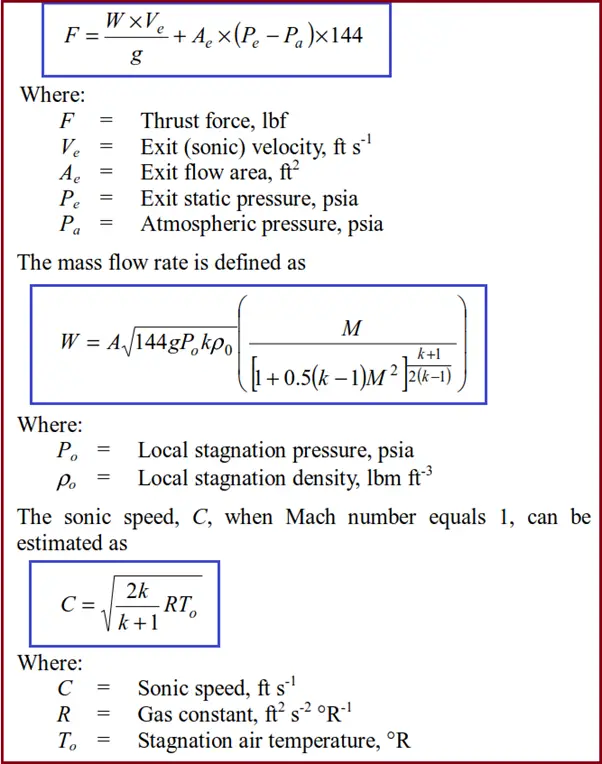
Calculation of Steam Blowing Thrust force at the end of Pipe Exit
The thrust force (F) of the jet at the pipe exit is estimated as
Hazards of Steam Blowing
Steam blowing poses several hazards, primarily due to the high-pressure steam used in the process. The intense force of the steam can cause severe burns, injuries, or fatalities if proper safety precautions are not followed. Additionally, the sudden release of steam and debris can create dangerous projectiles and high noise levels, which can further pose risks to personnel. The high-pressure environment also presents risks of equipment failure or malfunction, potentially leading to catastrophic failures or explosions if the system is not properly maintained and monitored. Implementing stringent safety measures, including protective gear, safety barriers, and thorough training, is crucial to mitigating these hazards and ensuring a safe steam-blowing operation.
Dear Anup:
We have a 160 kilometer pipeline (60″) internal Fusion Bonded Epoxy Coated that require cleaning form fin sands and flaked coating. The line is equipped with launcher/receiver pigging provision. However, we don’t prefer to perform foam pigging scraping as it is likely to cause more flaking of the coating. The line transports seawater and it is flange rating class 600.
We have a steaming plant at the receiving facility and the receiving facility is at higher altitude than the facility upstream of this pipeline. So, what do you consider best for cleaning the line that from the debris , sand and flaked coats which often cause us to do more filters changeout at the receiving facility.
regards,
how to find air blowing velocity
Pipe stress load cases are definitely something that needs to be considered. Both for boiler warming leading up to each steam blow and cooling during the blow. A boiler on a project I worked on a few years ago was severely damaged. Multiple tubes buckled because changes to the pressure – temperature profile during steam blowing was not considered. Admittedly, the boiler design was not ideal. It might have survived steady state temperature. However, multiple steam blows soon found the problem.
Dear Sir
what is stand for MCR here?
Thanks
MCR: Maximum continuous rating, Which is the capability of steam boiler/Generator to produce and provide the required quantity of steam continuously and easily without any unwanted effects.
Hi thanks for your paper about steam pipe lines very good. I working in power plant in fajr in iran. Good willing you are successful in.
Can you share a sample calculation for Calculation of Steam Blowing Thrust force at the end of Pipe Exit considering Upstream pressure before last isolation valve of 80Kgf/cm2(g), Temp. 350 Deg. C and downstream exhaust to atmosphere through 250Nb pipe for puffing method.
Great article and very informative. Thanks for the effort and your precious time. Your passion for your work will keep you humble and lift you to higher achievements.