
What is the Stress Intensification Factor or SIF?
As per Code ASME Section III, the Stress Intensification Factor or SIF is defined as the Fatigue Correlation Factors that compare the fatigue life of Piping Components (Tees, branch connections) to that of girth butt welds in straight pipe subjected to bending moments.
Note that, Stress Intensification factors are often confused with stress concentration factors, stress coefficients, or other stress indices used in various mechanical design and fracture mechanics problems. The stress intensification factor in piping stress analysis provides the fatigue correlation of piping elbow and branch connections for evaluating moment loading.
History of Stress Intensification Factor
Markl Fatigue Curve for Straight Pipe (Fig. 1):
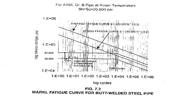
Markl stress intensity factor: iS = 245,000N-0.2
i =( CN-0.2)/S
Where
- i=Stress intensification factor
- C=245,000 for carbon steel materials
- N=Cycles to failure
- S=Nominal stress amplitude
Markl Stress Intensity Factor is based on deflection control, fully reversed, cyclic bending fatigue tests.
Stress Intensification Factor Equation
As per Section III, for class 2 & 3 piping and B31.1
Calculated stress S = i*M / Z
where
- M = (MX2 + MY2 + MZ2)1/2
- Z=Section Modulus
- i= Stress intensity factor
This approach is conservative.
Thermal expansion stress SE = (Sb2 + 4St2)1/2
where
- Sb=resultant bending stress
- St=torsional stress = Mt/2Z
The resultant bending stress is calculated by
Sb= [((iiMi)2 + (ioMo)2) ½]/Z
where
- ii = in-plane bending stress intensification factor (Refer to Fig. 3)
- io= out-of-plane stress intensification factor (Refer to Fig. 3)
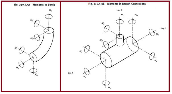
- Mi = in-plane bending moment (Refer to Fig. 2)
- Mo = out-of-plane bending moment (Refer to Fig. 2)
Eg: For 12” Std schedule long radius elbow.
a)Elbow without flange
- R1 = 1.5(12) = 18”
- T = 0.375” (Std) Assume the same thickness for pipe & elbow
- r2 = ( OD-T)/2 = 6.1875”
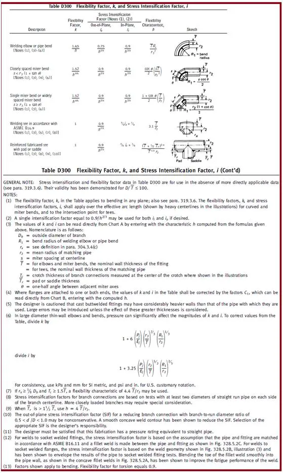
- h = (TR1 )/(r2)2= 0.176 (From table D-300 of B31.3)
- ii = 0.9 / h2/3 = 2.86
- io = 0.75/ h2/3 = 2.4
b)If one end is flanged the correction factor C1 = h1/6 = 0.7486
- ii = C1 ( 0.9 ) / h2/3 = 0.7486 x 2.86 = 2.14
- io = C1 ( 0.75)/ h2/3 = 0.7486 x 2.4 = 1.797
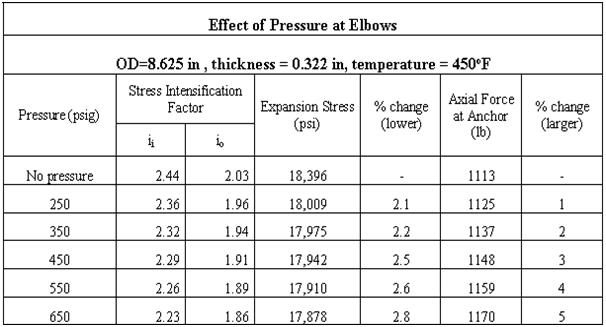
Pressure vs Stress Intensification Factor
Effect of Pressure on Stress Intensification Factor:
Finite Element Methods for Stress Intensification Factor Calculation
The various methods for calculating Stress Intensity Factor are
- Analytical Methods defined by Piping Codes
- FEM techniques
The user can see that the basic SIF procedure is:
- Build the model.
- Apply a moment through the nominal attached pipe.
- Read the highest stress from the resulting plot.
- Divide by M/Z to get the SIF.
The Fem Software widely used for calculating Sif are
- FE-pipe
- Ansys
Stress Intensification Factor Calculations
The basic definition of stress intensification factor (SIF) is:
SIF = (Actual Peak Stress in Part)/( Nominal Stress in Part)
The nominal stress in the part for a piping component subject to bending loads is M/Z where “M” is the moment that the pipe exerts on the component, and Z is the section modulus of the matching pipe welded to the part being analyzed.
Example Case:
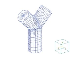
For example, when Stress Intensity Factors are needed for a large D/T “Wye” Fitting, there are usually four SIFs involved.
- one for the in-plane moment about the wye,
- one for the out-plane moment
- For both the main header and branch sections.
An example, demonstrating this calculation for a 32×0.375 wye fitting is shown in the example.
Markl’s definition of the SIF is the ratio of the actual stress in the part due to a moment “M”, divided by the nominal stress in a girth (circumferential) butt weld due to a similar moment “M”.
B31 Stress Intensity Factor (SIF) = Actual Stress in Part (due to M)/ Stress in Girth Butt Weld (due to M)
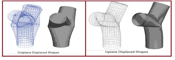
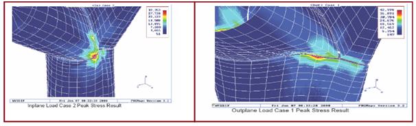
Two load cases for the model are set up automatically by FE/Pipe.
They are
- Operating, and
- Occasional
Various displacements and stresses from each load case are shown in Fig 6 and Fig 7.
Some more Resources that may be of your interest
Piping Elbow or Bend SIF (Stress Intensification Factor)
How to use ASME B31J-2017 and FEM for SIF and k-factors for Stress Analysis
ASME B 31J & B 31J Essentials: Why these are useful in Piping Stress Analysis?
Thanks for explaining that the nominal stress can be found by dividing the moment of the pipe by the section modulus of the matching pipe that’s welded to that part. Lately I’ve been interested in learning more about the future of welding technology. It’s was interesting to learn about some of the math involved in welding, so I’m glad you shared!
Appreciate your website. Explanation is clear and direct.