Ultrasonic testing, often abbreviated to either UT or Ultrasonic NDT, is an umbrella term for a number of non-destructive techniques used to detect the characteristics of a material. This type of testing involves using high-frequency ultrasound sound waves for the purposes of characteristic investigation. In this article, the characteristics of ultrasonic testing of welds will be discussed.
Non-destructive ultrasonic testing was first explored as early as 1942, by Dr. Floyd Firestone. He created a method to detect irregularities within the mass of material, even when they were invisible on the surface. Since then, other researchers have continued to refine the process, as well as expand the range of its utility.
What is Ultrasound?
Ultrasound refers to a frequency level that human beings are incapable of hearing. The overall ultrasound frequency range is 20,000 Hertz and above. In welding ultrasonic testing, the frequency used typically falls within the range of 500 Kilohertz to 20 MegaHertz.
Types of Ultrasonic Waves
There are four main types of waves used in non-destructive techniques like ultrasonic testing
1. Longitudinal waves
Longitudinal waves oscillate in the same direction as the propagation of the wave. The density of these waves fluctuates as they move. These waves can travel through liquids, gases, and solids through movements of compression and expansion.
2. Shear waves
Shear waves are also called transverse waves. In this type, the particles vibrate and move at a right angle to the direction of the wave’s propagation. These waves are stronger in solids than in other states of matter, though they are generally weaker when compared to longitudinal waves.
3. Surface waves
Surface waves are also called Rayleigh waves. The particle vibration of these waves is in the form of an elliptical orbit. These waves are extremely sensitive to surface irregularities and defects. They are also good at following curves and are useful in places where other waves cannot reach them.
4. Lamb waves
Lamb waves are also called plate waves. They are similar to Rayleigh waves, but cannot be generated in pieces that are thick. They require flat pieces that are only a few wavelengths thick.
Equipment/Tools Required for Ultrasonic testing
Transducer:
In ultrasonic testing, a transducer is a device that converts electrical energy into sound waves that travel through the piece being inspected and vice versa. Transducers are available in a variety of frequencies for different test pieces. There are many types of transducers, divided broadly into contact and non-contact devices.
Contact transducers require direct contact with the test piece. The shape and material of the transducer can vary. Also, the type, temperature, and thickness of the test piece will dictate the type of transducer being used, e.g. delay line transducer for thin pieces, dual line transducer for corroded or extremely hot pieces, etc. Contact transducers require couplants to enable the transmission of energy from the transducer to the surface of the test piece. Couplants are used to displace the air; they are usually in liquid or gel form.
Non-contact transducers or electromagnetic acoustic transducers do not require direct contact with the test piece to inspect it thoroughly. These transducers can be used in harsh temperatures and on most metals. As there is no physical contact, these transducers do not require couplants to facilitate transmission. However, unlike contact transducers, these devices are electromagnetic in nature and can therefore only be used on metallic or magnetic test pieces. Non-contact transducers are often used in welding ultrasonic testing.
Diagnostic machine:
A machine that records the signal of the pulse and the resulting echoes. These machines are also used to analyze the received data in different ways. The machine used will depend on the type of inspection being conducted, e.g. thickness gauging, flaw detection, etc. These machines can be either manual or automated, and either portable or not. Different types of diagnostic machines will be required for contact or immersion testing. The information presented on the equipment will also differ. There may or may not be a digital graphic of the signal. The machine must be calibrated on the basis of the properties of the test piece before it can be used for inspection.
Pulser and Receiver:
This is a device that can produce and receive ultrasonic energy of high frequencies. It is the connection between the transducer and the diagnostic machine. The pulsar emits controlled bursts of energy. The receiver section transports the echoes produced by the transducer to the diagnostic machine.
Ultrasonic Testing Procedure
Once the pulse receiver is connected to the transducer and a diagnostic device, the process of inspection begins. The active element of the transducer is passed over the piece being inspected.
There are multiple methods to carry out ultrasonic testing. These methods can be classified into three main categories:
1. Method of receiving ultrasound
a. Reflected transmission
In the reflected transmission method, a pulse of energy is sent through the test piece that continues until it hits a different medium, i.e. a border. It is usually the back wall of the piece. A reflected pulse or an echo is then emitted from the back wall. The intensity of the pulse and the echo are noted. In case of a crack or imperfection, the pulse will not reach the back wall, it will be reflected from the location of the imperfection, resulting in an echo signal of lower intensity.
b. Through/attenuated transmission
In this method, an ultrasound is sent through one surface of the test piece and is received by a separate receiver on the other side of the piece. In case of imperfection, the intensity of the sound received will be lower than usual. For this method, at least two sides of the test piece must be available. Also, this type is better for pinpointing the location of the crack, but the depth at which it is located can remain unclear.
2. Angle of sound waves
a. Normal beam
This refers to the angle at which the pulse is introduced to the test piece. A normal beam is a 90-degree angle. The normal beam method can be used for test pieces that are flat or smooth, with no unwieldy obstructions.
b. Angle beam
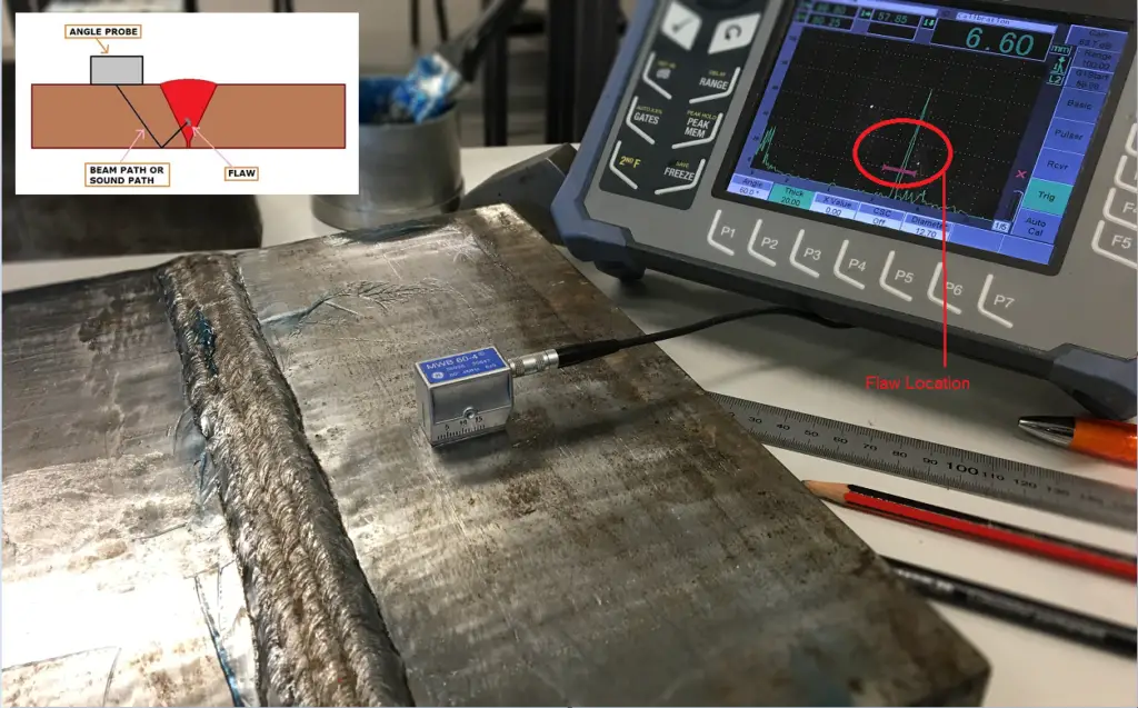
In this method, the pulse is emitted into the test piece at any angle other than 90 degrees. For this method, an angled transducer will be required for an easier sound introduction. This method is useful when the best way to get the largest reflection is at a diagonal. It is also useful in case some part of the test piece is obstructed, and normal beam inspection is not possible. This method is useful for determining the thickness of the test piece and the depth of the imperfection.
3. Method of coupling
a. Contact
In contact testing, a couplant is applied between the transducer and the test piece to reduce the air and increase the intensity of the sound waves.
b. Immersion
In immersion testing, the test piece and the transducer are both immersed in a bath. In this type of testing the water acts as the couplants. The movement of the transducer is smoother in this method of ultrasonic testing. In this method, direct physical contact between the transducer and the test piece is not required. Also, a specific immersion transducer is to be used for this method.
c. Non-contact
This is a type of testing that does not require contact and operates on principles of electromagnetism mechanics.
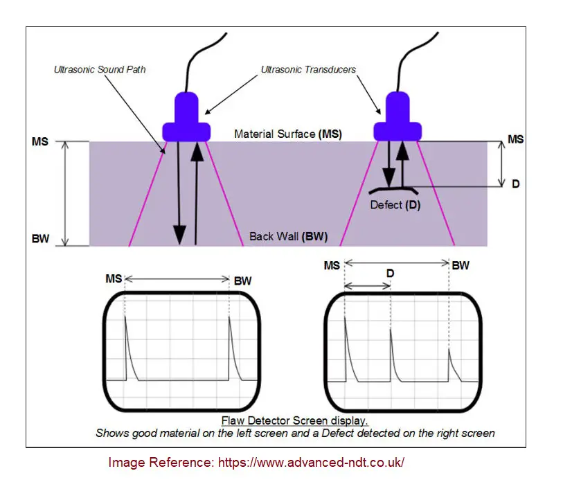
Fig. 1 shows the principle of Ultrasonic Testing.

An ultrasound transducer or ultrasonic probe sends a sound wave into a test material. Two indications are received from each probe; the first one is from the initial pulse of the probe, and the second one is from the back wall echo. If there is any defect, it creates a third indication (See the right side display in Fig. 1) and simultaneously reduces the amplitude of the back wall indication. The depth at which the defect is present can easily be calculated by dividing the length D by the length between MS and BW.
Common Data Formats for Ultrasonic Testing
1. A Scan
The A-Scan presents the data as the strength of the signal received and the time it took to receive it. The depth and size of the flaw can be determined using this type of scan by comparing the size and position of the signal on the scan.
2. B Scan
The B Scan is a cross-sectional scan of the test piece. In this type of presentation, the time taken for travel is presented with its distance to the transducer.
3. C Scan
The C Scan is a plane view of the test piece, with a sign indicating the position of the detected flaw. The plane view can be from the top, bottom, or side, depending on the position of the transducer.
With automated diagnostic machines and interfaces, all these types of charts are created automatically to provide an accurate analysis of the test piece. With progress in the field of ultrasound imaging, the quality of data presented has become more and more detailed. Now, it is possible to spot even minuscule irregularities.
Materials to be used on
Ultrasonic testing can be conducted on a variety of materials. It is applicable to most metals, alloys, and composites, as well as concrete, ceramics, plastic, and even wood. Ultrasonic testing is even used in the medical field, e.g. sonography.
Ultrasonic Testing of Welds
Welding is the process of fusing at least two parts by using methods like heat and/or pressure. Though welding is most commonly used on metals, it is also possible to weld thermoplastics and wood. A welding project that is complete is called a weldment. A weldment mainly consists of two materials: a parent component and a consumable. A parent component is the material of the parts that are going to be joined. A consumable, sometimes called a filler, is the material that is used to fuse the parts together.
Weldments can be either homogeneous or heterogeneous. Homogenous welds are those where the material of the consumable is compositionally similar to the material of the parent component. Consequently, in heterogeneous welds, the two materials are compositionally different. While homogenous weldments are generally preferred, heterogenous weldments have to be constructed in cases when the parent component is brittle or otherwise unstable.
Since welding is a high-heat and pressure process, it requires skill and practice to produce smoothly fused weldments that are flawless. Mistakes like hurrying the process, or letting the metal cool too soon can lead to cracks or other imperfections, which are sometimes located inside the weldment. They cannot be spotted from the surface but can compromise the strength of the welded product. This is why ultrasonic testing of welds is a good way to determine the quality and craftsmanship of a weldment without disassembling it.

1. Ultrasonic Testing of Welds for Flaw detection
Ultrasonic testing in welding can be used to detect defects and irregularities in test pieces. As a non-destructive method, it is completely non-invasive. However, it can still provide extremely accurate readings of flaws that lie beneath the surface of the item:
a. Porosity
Pores are extremely small voids in a component. They are formed when gas gets trapped in welding metal as it is solidifying. Pores are either distributed evenly throughout an item or are concentrated on one part. Pores are mostly spherical, but they can also look elongated.
b. Slag inclusions
Slag inclusions are non-metallic solid substances that are stuck within the welded metal. If welding is done too fast, or at the wrong angle, slag inclusions are likely to occur. Unless they are at the surface, these inclusions are impossible to spot without testing.
c. Lack of sidewall fusion
Lack of the smoothening of the fusion between the metal used for welding and the parent metal is called lack of sidewall fusion. This can happen if the arc length is too big and the metal melts over the side.
d. Lack of inter-run fusion
This is when the weld metal does not fuse the previous weld bead adequately.
e. Lack of root penetration
When both sides of the joint’s root region remain unfused, it is called a lack of root penetration.
f. Undercutting
An undercut is a type of welding defect where the cross-sectional thickness of the metal is reduced, thus lowering the strength of the weld and of the item itself. In industrial settings, equipment that has undercutting can be a safety concern and needs to be replaced.
g. Longitudinal or transverse cracks
Longitudinal cracks run across the center of the weld, while transverse cracks run perpendicular through the axis of the weld.
2. Ultrasonic Testing in Welding for Thickness detection
An ultrasonic thickness gauge is used to determine the thickness of an item by using sound waves to determine the time it takes for the sound waves to produce an echo. The thickness of an item is an important characteristic: the thickness of medical tubes and contact lenses needs to be standardized, and the thickness of heavy machinery is not only a matter of having no variables, but it is also a matter of safety. Also, ultrasonic testing of welds to determine their thickness is a great way to keep track of the corrosion levels of pipes and tanks.
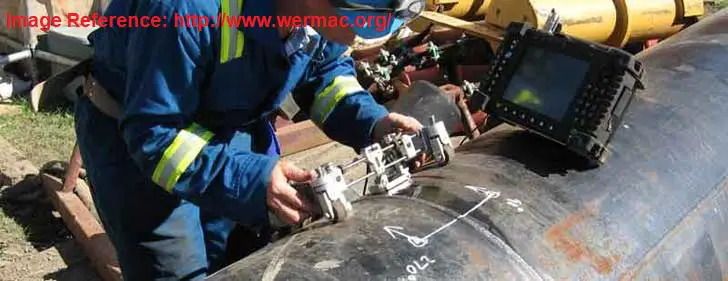
Fig. 3 below shows ultrasonic testing in the welding of pipe to detect any flaw in the piping weld.

Advantages of Ultrasonic Testing
- Detection of deep-rooted invisible flaws: Some flaws are not on the surface of an item. With ultrasonic testing, it is possible to identify flaws deep within the mass of the test piece.
- Detection of minuscule flaws: Ultrasonic testing can identify the presence of tiny flaws as well as big ones. With the equipment required for this method being upgraded constantly, the preciseness level is only increasing further.
- Possible even with only one surface: Some items being tested may be too corroded to move, welded into the wall, etc. In cases like this, it is not possible to move the item for testing. Thankfully, ultrasonic testing is possible even when the examiner only has access to one surface of the test piece.
- Accuracy at determining depth and thickness: Ultrasonic testing equipment can identify the precise location of a crack, as well as determine how big it is, without having to use invasive methods.
- May even determine the nature of the flaw: In some cases, it is also possible for an experienced examiner to identify the cause or origin of the flaw by analyzing the readings on the testing equipment.
- A non-destructive and safe method for inspectors: It is a completely non-destructive method and does not cause any harm to the items being tested. Additionally, it is a safe method for workers to examine the item, as it does not pose any health or safety concerns for the examiner.
- Highly automated: Diagnostic machines are now highly automated and capable of performing any calculations the examiner might need. Also, the machines not only organize the data but also present it in all three data formats commonly used in ultrasonic testing.
- Immediate results for quick decisions: The results of ultrasonic testing are instantly available to the examiner. This means that flaws are identified immediately, and consequent decisions can be taken without delay.
Disadvantages of Ultrasonic Testing
- Manual operation of the sensitive probe requires practice: As the probes are sensitive, they need to be handled with extreme care. This is because, even with couplants, probes can pick up a significant level of noise, which can hinder results.
- Technical knowledge required: Ultrasonic testing can be confusing without at least a basic understanding of the topic. To carry out this task, personnel will have to be given some technical training in this field. They will also need to practice their application methods a lot.
- Water-based couplants pose a danger to tested items, and need anti-freeze liquids: Water can be a danger to many items that are regularly tested using ultrasonic NDT. While it would be ideal for all test pieces to be water-resistant, this is not the case. And unfortunately, water-based couplants are the most common type of couplants. If they are to be used, it is advisable to use antifreeze on the item beforehand to prevent damage.
- Equipment requires calibration, and thick test pieces will need multiple setups: The diagnostic equipment has to be calibrated according to the features of every test piece, which can be very time-consuming. In cases where the piece is too thick, the equipment will have to be set up multiple times for a single test piece.

Dear Sir,
Kindly provide notes for UT of pipes/plate
Hey Anup kumar,
It was very nice information about NDT,
But I have one question for you, how can I get UT Test of weld joints easy to test it and difficult to test, b/c I just wondered if fillet weld is easy to test it than butt joint?
Best regards
Michael