What is WRC?
WRC or Welding Research Council is a Scientific Research Corporation, involved in solving problems related to welding and pressure vessel technology. To date, they have published more than 500 bulletins that solve various problems of engineering.
Importance of WRC 107 (WRC 537) and WRC 297 in Piping Stress Analysis
Whenever Pressure Vessel nozzle loads exceed the allowable values provided by Vendors (Equipment manufacturer) or standard project-specific tables (guidelines), the piping stress professional can use WRC 107 (537)/297 (or any other FEA) to calculate the stresses at the Nozzle-Shell junction point and compare the calculated stresses with allowable values provided by Codes. If the stresses are found to be within the allowable limit then the load and moment values can be accepted without any hesitation.
However, there are some boundary conditions that must be satisfied before using WRC. This write-up will explain the required details for performing WRC 107 (WRC 537) and WRC 297 using Caesar II software and the step-by-step methods for performing WRC checks.
What are WRC 107 (WRC 537) and WRC 297?
Both WRC 107 (537) and WRC 297 bulletins deal with “local” stress states in the vicinity of an attachment to a vessel or pipe. As indicated by their bulletin titles, WRC-107 can be used for attachments to both spherical and cylindrical shells while WRC-297 only addresses cylinder-to-cylinder connections.
Both bulletins are used for nozzle connection. WRC-107 is based on an un-penetrated shell, while WRC-297 assumes a circular opening in a vessel. Furthermore, WRC-107 defines values for solid and hollow attachments of either round or rectangular shape for spherical shells but drops the solid/hollow distinction for attachments to cylindrical shells. WRC-297, on the other hand, is intended only for cylindrical nozzles attached to cylindrical shells.
Boundary conditions for using WRC 107/ WRC 537
To determine whether the WRC 107/ WRC 537 bulletin can be used for local stress checking, the following geometry guidelines must be met:
- d/D<0.33
- Dm/T=(D-T)/T>50 (Here, T=Vessel Thickness, Dm=mean diameter of vessel)
Boundary conditions for using WRC 297
To determine whether the WRC 297 bulletin can be used for local stress checking, the following geometry guidelines must be met:
- d/D<=0.5
- d/t>=20 and d/t<=100 (Here t=nozzle thickness)
- D/T>=20 and D/T<=2500
- d/T>=5
- The nozzle must be isolated (it may not be close to a discontinuity) – not within 2√(DT) on the vessel and not within 2√(dt) on the nozzle
Difference between WRC 107 (WRC 537) and WRC 297
The major differences other than the boundary conditions mentioned above are listed below:
1. WRC 107 calculates only the vessel stresses while WRC 297 calculates Vessel stresses along with nozzle stresses.
2. WRC 297 is applicable only for normally (perpendicular) intersecting two cylindrical shells whereas WRC 107 is applicable for cylindrical as well as spherical shells of any intersection.
3. The attachments for WRC 297 checking must be hollow but WRC 107 analyzes cylindrical or rectangular attachments that can be rigid or hollow.
4. WRC 297 is not applicable for nozzles protruding inside the vessel (Fig 1), Tangential Nozzle (Fig 2), and Nozzle at an angle (Fig 3).
5. Typically, WRC-107 is used for local stress calculations and WRC-297 is used for flexibility calculations.
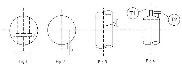
Limitations of WRC 107 (WRC 537) & WRC 297
Other than the boundary conditions mentioned above there are some more limitations as mentioned below:
- Neither bulletin considers shell reinforcement nor do they address stress due to pressure.
- CAESAR II, PVElite, & CodeCalc will not extrapolate data from the charts when the geometric limitations mentioned above are exceeded. Extrapolated data may not be appropriate.
WRC-107/ WRC-297 Calculation Methodology in Caesar II
Inputs required for performing WRC checking
The following documents must be ready with you before you start to perform WRC 107/297 checking:
- Equipment Details/ General Arrangement Drawing
- Nozzle details
- Line list
WRC Calculation Steps in Caesar II
Step 1: Perform Static analysis of the stress system and find out the nozzle loads required for checking local stresses.
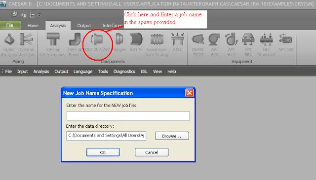
Step 2: Enter the WRC module from Caesar II. Provide a file name for your job. Refer to Fig. 2
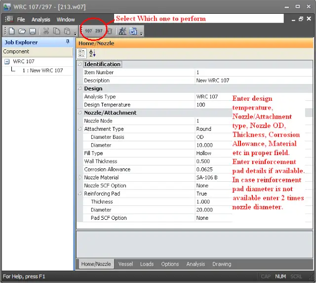
Step 3: The following screen will appear. Enter the Nozzle data as shown in Fig. 3 below.
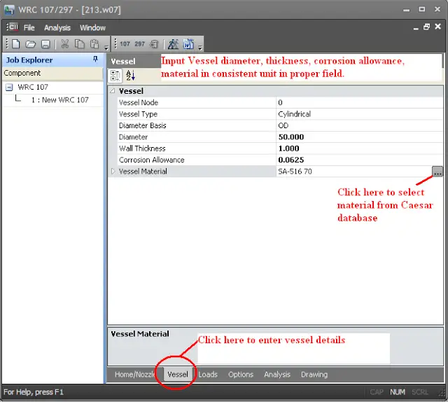
Step 4: Now enter the vessel details i.e, diameter, wall thickness, corrosion allowance, and material (Fig. 4)
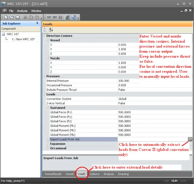
Step 5: Input vessel and Nozzle direction cosines, Internal design pressure, and load and moments values from Caesar static analysis output (Sustained, Expansion, and occasional as applicable).
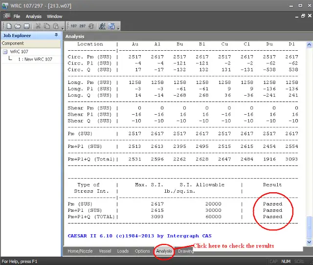
Step 6: On options, it is suggested not to change any parameter. Now click on analysis to read the results. The output will inform you whether WRC checking is passing or failing. Use results as per your requirements.
For entering loads and moments as per local convention following description and figure (Fig. 7) can be used for converting global forces into local forces.
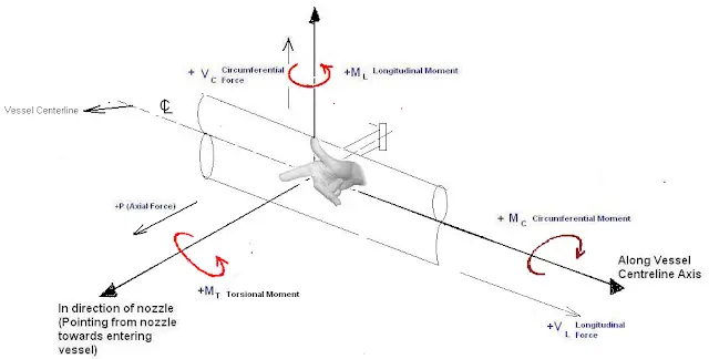
As shown in Fig. 7, Stretch your right hand with the Middle finger along the Vessel Centerline. Index Finger should parallel to the nozzle centerline and should point in a direction from the nozzle towards entering the vessel. And the Thumb should be perpendicular to both. Then
- The direction of the Index Finger represents +P.
- The direction of the Middle Finger represents +VL
- The direction of the Thumb represents +VC
- ML will be positive if by applying the right-hand thumb rule to ML, the direction of thumb is the same as that of VC.
- MC will be positive if by applying the right-hand thumb rule to MC, the direction of thumb is opposite to the direction of VL.
- MT will be positive if by applying the right-hand thumb rule to MT, the direction of the thumb is opposite to the direction of P. Get the loads and moments from CAESAR output. Compare the direction of Forces and Moments in CAESAR output with conventional Force and Moment directions and enter the values of P, VL, VC, MT, MC, and ML accordingly.
Few more Handpicked Resources for you…
Seismic Analysis using Caesar II
Wind Analysis using Caesar II
Stress Analysis of Pump Piping System
Stress Analysis of Centrifugal Compressor Piping System
Modelling Shell and Tube Heat Exchanger in Caesar II
Piping Stress Analysis Basics
Piping Stress Analysis using Caesar II
Piping Stress Analysis using Start-Prof
Piping Design and Layout Basics
Some Useful Literature related to Piping Interface Departments

HI ANUP,
GREAT TO SEE YOUR BLOG!! AS ALWAYS WELL EXPLAINED..
KEEP IT UP!!
hardik pilojpara
reliance
Thanks a lot…
Regarding Note 5, where is it based that WRC-107 is typically used for local load calculations whereas WRC-297 for nozzle flexibility? If the loads calculated by WRC-297 are higher and/or nozzle local loads are exceeded, would you still go by WRC-107 and determine the connection to be safe?
I am puzzled by this note, although I do not have a clear position on the issue myself.
Nice Blog,
Best Regards,
It’s a very very useful & nice blog. Thanks a lot for knowledge sharing.
Very nice blog !!
Thanks for sharing
Why are you not applying pressure thrust option as True?
Do you have any valid reason for not using it. Can you explain why you used pressure thrust as false?
The blog writer effort is appreciated. It is good thing the he kept the controversial subject, such as thrust load, out of the discussions. Thrust load inclusion or exclusion is very much controversial among the users. I have not seen a consensus view on this among the users. Many users have experienced impractical results when thrust load due to internal pressure is used. It is an option in the program as the program developer, I think, is not sure about it and leaves it up to the users.
There is a commercial program named FE Pipe/NozzlePro by the PRC Group available now. It is a finite element analysis program for nozzle load analysis. In this program, geometrical constrains of the WRC 107/297 are eliminated and is very easy to use even by a novice. In many EPC companies, the WRC methods for nozzle load analysis have been replaced by the FE Pipe/NozzlePro.
please explain about the lines
Other than boundary conditions mentioned above there are few more limitations as mentioned below:
1. Neither bulletin considers shell reinforcement nor do they address stress due to pressure.
Hi
i have flange connection like Fig 4 (T2).Could somebody tell me how can I use WRC107because the direction cosine of the vessel and Nozzle is same, so the error is come up.
Thanks
Farhad
I developed my own software for WRC 537 (WRC 107). It is validated against PVElite & Compress. Free version can be downloaded at:
https://www.fayazmemon.com/old/FMSoft_Nozzle_Stress.html
Fayaz
correct me if I wrong WRC107 does not consider pentrated shell, reinformcement pad nor nozzle stress. how can your software calculates nozzle stress? it should be shell local stress?
In spite of what demonstrated in Fig 2 of WRC 107 , the table 5 of the same reference calls for positive sign of radial load P when its direction is toward vessel inside space. Isn’t it in contradiction to what clarified in above?
Hi,
Can WRC-107 check be performed to check stresses welded pipe shoes?
Regards
Keep up the good job.
Hello what’s the diferent between API 650 and WRC 297 and when I use each one?
Thank you very much Great
Good afternoon,
Could you please clarify a doubt?
Does Caesar II already perform boundary condition checking to use WRC 107 and 297?