
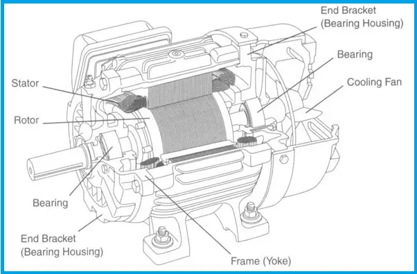
How Electrical Motor Works
- The rotor has fixed magnetic fields
- The stator receives current from the drive which creates a magnetic field.
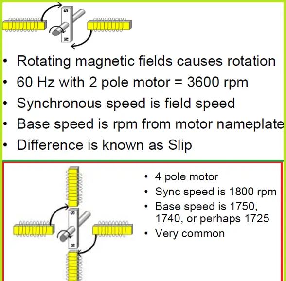
- This rotating magnetic field moves the rotor
- The frequency is how often the current flows through the stator.
- Synchronous Speed = (120 * frequency) / # Poles =(120 * 60Hz ) / 4 = 1800 rpm
Methods of Pump speed control
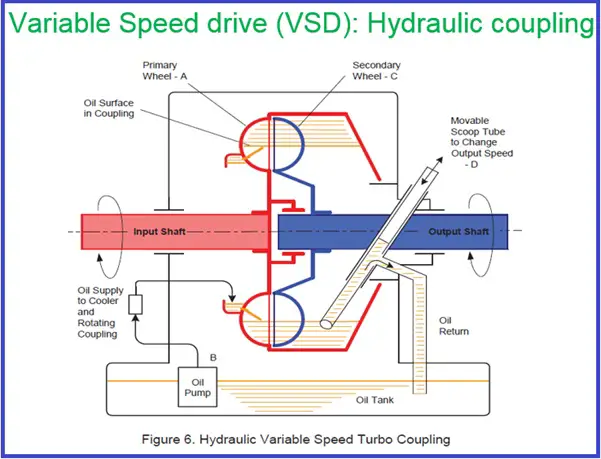
Variable Frequency Drive (VFD)-
- It converts fixed frequency three-phase Power input to variable frequency three phase output to Motor.
- The output frequency is greater or less than the supply frequency.
- Generally, the frequency is lower or the same as the supply frequency due to motor constraints.
- Motor Speed = (120 * frequency) / # Poles
Basis of Centrifugal Pump Operation:
- Pump characteristics curve (H-Q curve)-Pump specific
- System resistance curve- System specific
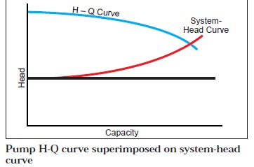
The conventional way of Flow control:
- By installing a Control valve at the pump discharge will be throttled to control the required flow.
- The pump will follow the pump curve
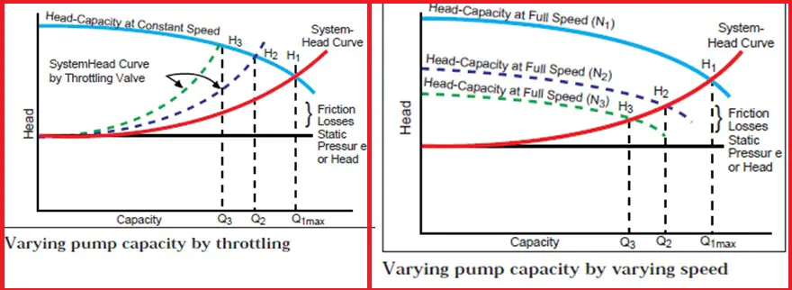
Flow Control using speed control:
- By changing the pump speed using VFD / VSD, the Pump flow rate will change.
- The pump will follow the system resistance curve.
The behavior of pump speed control :
- VFD/VSD follows the system curve by changing the pump speed.
- VFD/VSD pump retains its characteristic performance curve shape.
- % change in speed changes the same % of flow rate if no static head is available.
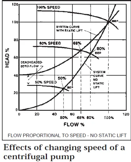
- The pump can be operated within the operating envelope provided by the pump vendor, and flow and corresponding head can be achieved within the operating envelope along with the system resistance curve.
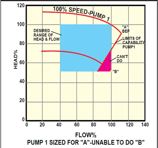
Specifying Speed control pumps:
- Like any fixed-speed pump VS pumps also required proper sizing.
- To achieve all desired head Vs flow ranges for VS pump all anticipated cases shall be provided to the vendor for all Sp.Gr. (fig. shows a pump can not reach point B)
Specifying VFD pumps:
- NPSHr and Motor HP shall be adequate for all flow and head ranges.
- NPSHr also depends on the viscosity and its effects shall be confirmed with the pump vendor.
- At lower flow rates generally, HPSHr increases, following the bathtub curve and the same shall be confirmed with the vendor.
Benefits of Speed control:
- No need for a throttling valve to operate the pump at desired flow and head.
- Control By-pass valve / MCF valve can be avoided.
- Reduced capital and maintenance cost of throttling valve and bypass valve.
- Reduction in the required head (Delta P required for throttling valve)
- Power saving at reduced flow requirements
- Reduced heat dissipated to pumping fluid for fixed speed pump as efficiency is lower at reduced flow.
- Start-up of high HP machine i.e compressor, Pump, etc. at a lower speed.
Why different operating points?
- Oversizing of the pump by adding a safety margin.
- Reduced production over the life cycle.
- Different destinations- one at a time.
- Changes in physical properties of fluids. (emulsions with different water cuts)
- Changes in piping roughness over a life.
- The single pipeline is used for multiple products.
- Fluctuations in destination pressure (MOL line)
When VFD/VSD application is economical?
- If the static head is lower than 50 % of the total head required. The required flow is 50% of the design value and may require 20% of the time.
- If reduced duty is between 60-80% of BEP (Proper sizing of pump for required duty) Only VFD application may not be sufficient for the control range
Additional requirements for Motor with VFD:
- Motor operated on VFD generates higher Temp. due to the irregular shape of electrical waveforms produced by VFD. Thus motor efficiency will be reduced due to high operating temperature
- To ensure the motor will not overheat, the motor is typically de-rated at full load from 3 to 10%.
- Increase heat can lead to environmental hazards as motor skin temperature may increase. A specially designed motor or de-rated motor shall be used.
- Sometimes special motor bearings shall be proposed to work in a high-temperature environment.
- Generally, the motor shall be specified as suitable for VFD and shall purchase from the pump supplier.
- May need an additional cooling fan for motor cooling at low motor speed.
- Additional Capex for VFD
- Need additional space in the control room for VFD installation
- Additional Air conditioning requirement.
- If installed outdoors cost of additional enclosure and additional air conditioning is very high.
VSD vs VFD?
- VSD is economical up to 80% of speed. losses increase below 80% speed and VFD becomes the only economical option compare to VSD.
- VFD can be configured with a fail-safe characteristic and the pump can run at full speed, however, VSD can not.
- VFD can be bypassed if a full-speed operation is required, however, the VSD is dedicated to the machine and can not be bypassed.
Is it worth it?
- Despite the need for additional Capx and special requirements, VFD/VSD pumping can save money. But System economics shall be studied properly.
- VFD/ VSD eliminates the requirement of a throttling valve, Bypass valve, and Motor starter and reduces power requirements shall be properly considered while analyzing economics.
- For start-ups of high HP machines – VFD/VSD eliminates the requirement of an additional power turbine in some cases.
Typical capacity control:
- Suction pressure control as a capacity control
- Discharge pressure control as a high-pressure control.
- Station capacity is controlled by pressure or level which manipulates the pump speed through cascade control to maintain desired suction pressure/tank level.
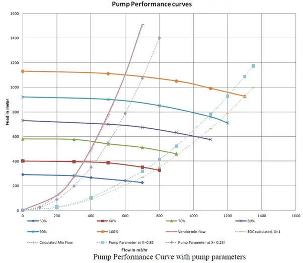
End of curve control:
- The end-of-curve operation could be a concern in pumping in large oil pipelines where the back pressure (system resistance) can vary.
- For fixed-speed pumps, based on flow the pump minimum and end-of-curve operation can easily be defined.
- For variable-speed pumps, the flow value is not an indication of the pump operating point in the performance curve. Hence pump parameter is defined based on flow and head.
- Pump parameter X is defined as X= K* (flow)^2/Delta P
- The pump Parameter is a constant line on the performance map which defines the pump’s relative operating point
- If the system resistance curve is very steep, it is not possible to control/maintain the pump end-of-curve operation using speed.
- Once system resistance moves away from the performance map, the control system needs another handle to increase the resistance.
- This is generally achieved by a control valve on the common discharge line.
Awesome post thanks for sharing a lot of good information.
I’m trying to learn more about VFDs. Thank you. So if a VFD has pump motor operating at 5-8 Hz for sustained periods throughout the day AND the pump can not discharge the fluid at that low RPM, will the fluid heat up not only from the churning impeller but also from the added heat to the shaft?