Compressed air systems are an essential component in many industrial and commercial operations. They provide a versatile and reliable source of energy that powers various tools and processes.
What is a Compressed Air System?
A compressed air system is a network of equipment designed to convert atmospheric air into a high-pressure source of energy. This system consists of several key components, including air compressors, storage tanks, air treatment equipment, and distribution piping. Compressed air can be used for a multitude of applications, ranging from powering pneumatic tools to actuating machinery and performing process operations.
Why do we need a Compressed Air System?
Compressed Air (CA) is a major prime-mover for the modern industry. Compressed Air is referred to as the fourth utility after electricity, gas, and water. A properly managed Compressed Air system can:
- save energy
- reduce maintenance & decrease downtime
- increase throughput
- improve product quality depending on its end-use
Compressed Air Quality
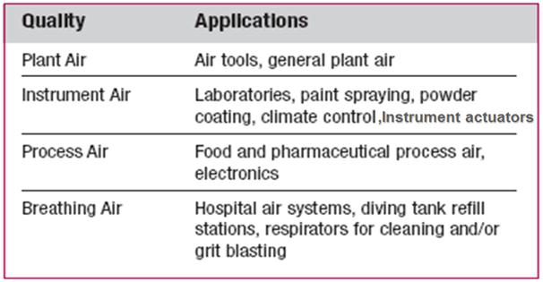
Compressed Air quality ranges from Plant air to Breathing air depending upon the end-user. Quality is determined by the dryness & the contaminant level. Higher the quality, the higher the cost. The following figure (Fig. 1) gives the applications of compressed air with respect to quality.
Components of a Compressed Air system
Compressed air systems consist of:
- a supply side which includes compressors and air treatment
- a demand side, which includes distribution and storage systems and end-use equipment.
A Compressed Air system broadly consists of:
Air Compressor
- The heart of the compressed air system, the air compressor is responsible for drawing in ambient air and compressing it to a higher pressure. There are several types of compressors, including:
- Reciprocating Compressors: Utilize a piston mechanism to compress air.
- Rotary Screw Compressors: Use two interlocking screws to compress air, providing a continuous flow.
- Centrifugal Compressors: Use a rotating impeller to compress air, suitable for high-capacity applications.
Air Storage Tanks
- These tanks store compressed air, helping to balance the supply and demand. They allow for peak demand management and reduce the frequency of compressor operation, leading to increased efficiency and extended equipment life.
Air Treatment Equipment
- To ensure the quality of the compressed air, treatment equipment is necessary. This includes:
- Filters: Remove dirt, moisture, and other contaminants.
- Dryers: Reduce humidity in the air to prevent corrosion and other issues in pneumatic tools.
- Regulators: Control the pressure of the air delivered to various tools and machinery.
Distribution System
- A network of pipes and hoses transports compressed air from the compressor and storage tanks to the point of use. Proper design and maintenance of this system are critical to minimize pressure drops and energy losses.
Control Systems
- Advanced compressed air systems may incorporate control systems that monitor and adjust the operation of the compressor, storage, and treatment equipment to optimize performance and energy efficiency.
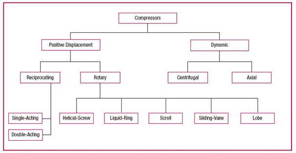
Air Compressor Types (Fig. 2)
- The Air compressor is the heart of any CA system.
- There are two basic compressor types: positive-displacement and dynamic.
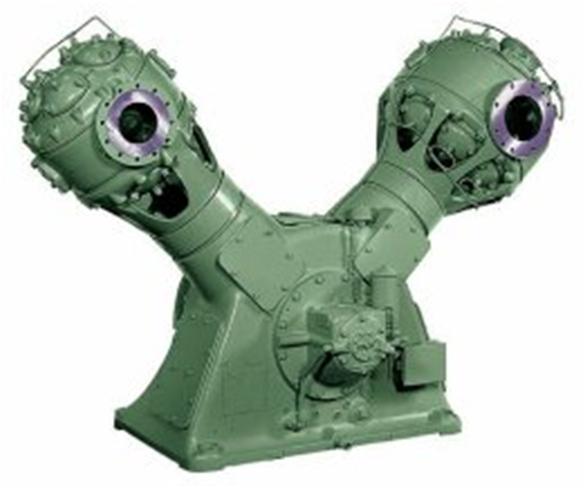
Reciprocating Compressor (Fig. 3)
This is a very versatile type of compressor and can be used for nearly all industrial applications. These are constant-capacity machines & deliver the air in pulses.
Characteristics are:
- High discharge pressures & relatively low to moderate volumetric flows (600-3000 cfm with a pressure range of 2000-5000 PSIG)
- Generally more maintenance intensive due to the many wearing parts
- It can be single-acting or double-acting, single-stage or multi-stage, air-cooled or water-cooled and lubricated or non-lubricated.
- High efficiencies
- Occupy larger footprint
- Higher capital cost
- Control is usually by Load-unload with 3 or 5 step capacity control
Multi-staging
Multistage machines are used in place of single-stage ones for the following reasons:
- Single-stage compression would generate excessive heat from compression
- MOC would have to be of high grade and hence expensive
- The power consumption of a single machine would be higher
- Better efficiency
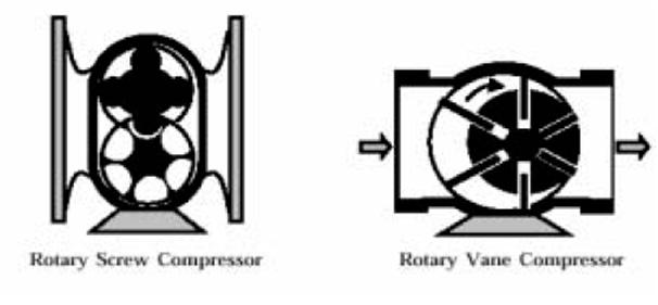
Rotary Compressor (Fig. 4)
The most common type of rotary compressor is the helical-twin, screw type. Less common types include sliding vane, liquid-ring, and lobe.
Characteristics are:
- Not usually suited for high discharge pressures & are most efficient for moderate air flows & low pressures (3000-6000 cfm with a pressure range of 300-400 PSIG)
- Low initial cost, compact size, low weight, and easy to maintain.
- Dry or oil-flooded type
- Lower efficiency
- VSDs provide good capacity control
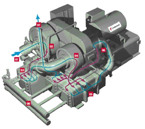
Centrifugal Compressor (Fig. 5)
Centrifugal compressor develops pressure by increasing the velocity of the air going through the impeller & then recovering the velocity in a controlled manner to achieve the desired flow and pressure.
Best suited for continuous air flows in large quantities.
Characteristics are:
- The heat generated & power consumption is lower.
- The space requirement & maintenance is minimum.
- Inherently non-lubricated.
- Available for flows ranging from 300 to more than 100,000 cfm, but the common ones are 1200-5000 cfm with a pressure range of up to 125 PSIG.
- Capacity control by inlet valve/guide vane throttling
- Surge/choke phenomena
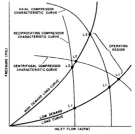
Characteristic curves
The characteristic curve (Fig. 6) of a compressor plots its discharge pressure as a function of flow.
Selection criteria
- Flow rate
- Discharge pressure
- End-use of the air
- Energy efficiency
- Reliability
Compressor sizing
Estimation of Compressed air consumption:
- Instrument air requirement
- 5 nm3/hr per CV
- 0 nm3/hr per ROV
- The plant (Utility) air requirement
- Compressed air requirement for pneumatic equipment, etc. operating in full load condition
Compressor Discharge pressure
- end-use pressure (for instrument air, minimum 7 bar g)
- plus all the pressure drops in the system.
Compressor Controls
Compressed air system controls serve to match compressor supply with system demand. Proper control is essential to efficient operation & high performance.
System controls include:
- Start/Stop
- Load/Unload
- Dual control
- Modulating
- Speed variation
- Pressure/Flow controls
Minimum Instrumentation required
Indications/alarms/trips consist of 3 major systems: Compressor, Lube oil & Cooling Water
Lube Oil system
Minimum alarms
- Low oil pressure
- Low oil level in the reservoir
- High oil filter differential pressure
- High oil temperature
- The high thrust bearing metal temperature
Temperature gauges
- Oil piping to & from coolers
- The outlet of each radial & thrust bearing
Pressure gauges
- Discharge of the oil pump
- On bearing header
- On control oil line & seal oil line
Compressor
- Pressure indicator at inlet, inter-stage & discharge
- Pressure switch at discharge
- Temperature indicator/alarm at inlet, inter-stage, and outlet
- The temperature gauge on the bearings
- Vibration switches
- A safety valve on each stage (for reciprocating type only)
- Flowmeter (if required)
CW System
- Pressure & temperature gauge on CW inlet
- The temperature gauge on CW outlet
- The thermal relief valve on CW outlet
Contaminants in Compressed air
The 3 major contaminants in Compressed Air are:
- Water
- Oil
- Dirt
Compressed Air System Components/Accessories
The standard components/accessories include:
Prime Mover
The prime mover is the main power source providing energy to drive the compressor. This power can be provided by any of the following sources:
- Electric motors: Economic, reliable, efficient
- Diesel/natural gas engines: Fuel availability, higher maintenance, high cost/uncertainty of power
- Steam turbines & combustion turbines: Inexpensive steam availability
Intercoolers/Aftercoolers
- Air-cooled/water-cooled
- Minimum pressure drop
- Regular maintenance
Moisture/oil separators
- Separation of condensed moisture/oil
- Types – Impingement baffle type, Centrifugal type, with Demister pads.
Pulsation Dampeners
- Reduce/eliminate pulsations of reciprocating machines
- Installed at the outlet of each stage
Receivers
- Storage for utilization at peak load
- Draining of condensed water
- Reduce pulsations from reciprocating machines
- Receiver sizing is based on hold-up for a drop in pressure level, say 10 minutes for a pressure drop of 3 bar.
- Provided with standard accessories.
Air filters
Suction filters or Post-compression filters.
Felt cloth filters are used for suction. Compressed air filters can be:
- Coarse particle filters (filter media can be a ceramic candle, felt cloth, etc)
- Coalescing & activated carbon filters
- Microfilter (high efficiency for special uses such as breathing air, etc) Minimum pressure drop
Drain traps
- Manual
- Mechanical float type
- Electronic timer operated
- Auto drain traps – condensate sensing
- Regular maintenance is required to avoid CA wastage
Lube oil coolers
- To remove heat from the lube oil
- Usually Shell & tube type with CW
Air distribution piping
- Least pressure drop in the system to reduce operating costs. The maximum pressure drop between the compressor and the farthest end of compressed air consumption should be around 0.3 bar
- Velocities between 6-10m/s in air mains; this will limit the DP & thus energy consumption and also allow moisture to precipitate
- Minimum bends & joints (long radius bends to be used)
- Arrangement for draining of moisture at regular intervals, slope provision
- Minimum expanders/reducers
- Leakproof joints, proper piping supports
- Gauges are to be provided at different locations to monitor the system pressure & temperature.
Compressor Cooling system
Cooling plays an important role in energy efficiency, two types are:
- Air-cooled – In-efficient, preferred only for low-capacity compressors
- Water-cooled – Efficient, used for high-capacity compressors
Water is circulated in a jacket around the cylinders to remove the heat resulting from compression & friction due to the sliding of pistons. Water is also required for the inter/aftercoolers and lube-oil coolers.
CW consumption for inter/aftercoolers can be estimated based on the compression ratio per stage assuming an adiabatic efficiency.
Generally, per the thumb rule,

Compressed air plant layout and distribution
Plant layout:
- Centralized layout
- All compressors installed in a single house, cost-effectiveness as maximum plant space utilization
- More pressure drop expected
- Decentralized layout
- Suitable for large industries, different levels/pressures of air
- Compressor situated at the maximum user location, less pressure drop, max energy utilization
- This can lead to noise and heat inside the plant
Compressor location
- The location should be such that compressor can induct clean, dry, and cool air
- Interesting fact:- every 4°C reduction in air intake temp reduces power consumption by 1%
- Points to be remembered while selecting the location of the air compressor:
- Low humidity to reduce water entrainment
- Adequate ventilation especially for air-cooled units
- Minimum suction piping
- Minimum bends
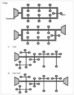
Compressed air distribution (Fig. 7)
Codes
- API 617 Centrifugal compressors
- API 618 Reciprocating compressors
- API 619 Rotary-type positive displacement compressors
- API 672 Packaged integrally geared centrifugal air compressors
Applications of Compressed Air Systems
Compressed air systems have a wide range of applications across various industries. Some common uses include:
1. Manufacturing and Assembly
- Pneumatic Tools: Tools such as drills, wrenches, and hammers are powered by compressed air, allowing for greater efficiency compared to electric counterparts.
- Material Handling: Compressed air is used in conveyor systems and automated guided vehicles (AGVs) for transporting materials.
2. Food and Beverage Industry
- Packaging: Compressed air is used for sealing and packaging products, ensuring hygiene and efficiency.
- Process Control: Many processes in food and beverage production require precise control of air pressure and flow.
3. Automotive Industry
- Paint Spraying: Compressed air systems are crucial for paint application in vehicle manufacturing, providing a smooth and even coat.
- Assembly Line Operations: Pneumatic tools are widely used in assembly lines for tasks like fastening and lifting.
4. Healthcare
- Medical Equipment: Compressed air is utilized in various medical devices, such as ventilators and dental chairs, ensuring reliability and safety.
5. Construction
- Heavy Machinery: Tools like jackhammers and nail guns rely on compressed air for their operation, improving efficiency on job sites.
Benefits of Compressed Air Systems
Compressed air systems offer numerous advantages that make them a preferred choice for many industries:
1. Versatility
- Compressed air can power a wide array of tools and equipment, making it suitable for various applications across different sectors.
2. Safety
- Unlike electricity, compressed air poses minimal fire and explosion risks, making it a safer alternative in hazardous environments.
3. Clean Energy Source
- When properly treated, compressed air is clean and free from contaminants, making it ideal for applications in sensitive environments, such as food production and pharmaceuticals.
4. Reliability
- Compressed air systems can provide a consistent and uninterrupted power source, crucial for maintaining productivity in manufacturing and other operations.
5. Energy Efficiency
- Advanced control systems and energy-saving technologies can help optimize compressed air systems, leading to significant reductions in energy consumption and operational costs.
In conclusion, the compressed air systems are a vital component of many industrial processes, offering versatility, reliability, and safety. Understanding their components, applications, and challenges is essential for optimizing performance and efficiency.

Thanks for helping me understand that compressor air systems should be controlled properly to ensure that they are efficient and would perform well. I guess this would be applicable as well for compressor system overhaul projects. They must be in great condition after the process for the safety of the operator and the device as well once it is used for various purposes.