
Purpose of Cooling Water System
The scope of a cooling water system is to provide the necessary cooling duty to heat exchange equipment and rotating equipment for removing the unrecoverable heat excess, no more easily and economically exploitable.
Cooling duty is always a lost duty; therefore cooling water should be used only when the heat cannot be recovered by other means. The cooling water system is considered to be a critical utility system; local or total loss of cooling water is a primary cause of process plant upset with failure of machinery equipment, column pressurization; leads to, PSVs opening; causes plant or complex shutdown, depending on the complexity of the CW network. Therefore the reliability of operation of the system components and the equipment sparing philosophy have primary importance.
Selection of Cooling Water System
A cooling water system should be used when the process heat is available at a low temperature (below 60°C), no more easily exploited, and the process outlet temperature must be lower than the ambient air temperature. This is the reason why it’s common to use an air cooler with a water cooler downstream; the temperature limit between the air cooler outlet and the water cooler inlet is the one indicated above.
The aforementioned temperature ranges shall be taken as a reference for selecting the appropriate cooling system. They depend on on-site conditions; the edge temperature value could be shown in Client documentation (BEDD). Site conditions limit the design options and the possible ways to operate the cooling system. They are defined by the local climate, the availability of water for cooling and discharge, the available space for construction, and the surrounding area’s sensitivity to emissions.
The local climate affects the temperature of the cooling water and air.
In general, cooling systems are designed considering the cooling requirements under the least favorable climatic conditions that can occur locally, i.e. with design values of wet and dry bulb temperatures. These data should be stated in BEDD.
The higher the bulb temperatures the more difficult is to cool down to low-end temperatures of the process.
Configuration of Cooling Water System
There are different types of cooling water systems: lake or basin cooling, once-through, open recirculation (evaporative), and closed recirculation (not evaporative).
Lake or Basin Cooling
In this kind of cooling system, the water used to cool down the excess heat of the process is discharged directly into a lake or basin where is cooled gradually by means of natural evaporation, radiation, and convection at a suitable temperature to re-use.
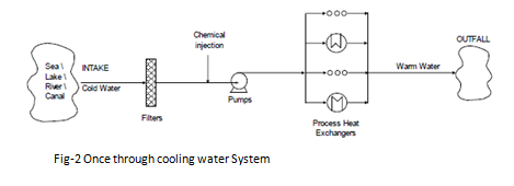
Once through system
Cooling systems that use cooling water on a one-time basis before discharging it directly to the outfall are termed once-through cooling systems. Since even small cooling systems operating on a once-through basis use relatively large amounts of cooling water, these systems are generally employed only where water at a suitably low temperature is readily available in large volumes and at low costs.
The usual source of once-through cooling water is from the sea; rivers or lakes (see Figure 2).
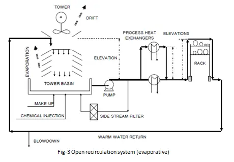
Open recirculation system (evaporative)
An open recirculation system incorporates a cooling tower to dissipate the heat removed from the process. It takes water from the cooling tower basin, passes water through equipment requiring cooling, and then returns the warm water to the evaporation unit, where the evaporated water cools down the water that recirculates.
The open recirculation system repeats the process of reuse, taking insufficient freshwater makeup to balance the water evaporated and drifted and the blow-down from the system to control the chemical characteristics of the recirculation water. This greatly reduces water demand and discharge. However, such a system also intensifies the potential for scaling, fouling, and corrosion. The number of concentration cycles should normally be in the range of 3 to 5 unless very strict requirements forced to use a lower number;
If fresh sweet water is not available for make-up, an evaporative system with seawater can be used, if the site is close to the sea. The open recirculation system uses only 10% of make-up flow compared with the total flow of a once-through system with seawater. For a seawater evaporative system, the number of concentration cycles must be kept at only 1.2, max of 1.3. With seawater, materials are of course more valuable than an evaporative system with sweet water. A disadvantage of the seawater evaporative system is the formation of saline moistness close to the sea cooling towers.
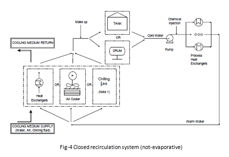
Closed recirculation system (not-evaporative)
In a closed recirculation system, water is recirculated in a close circuit with negligible evaporation or exposure to the atmosphere or other influences that would affect the chemistry of the water in the system. Heat is transferred to the closed cooling water system by typical heat exchange equipment and is removed from the closed recirculation system by a second exchange of heat from the closed system to a secondary cooling system. The secondary system could use either evaporative or once-through cooling or air cooling.
These systems usually require strong chemical treatment on the make-up water but, since water losses are negligible and make-up water flow is low, these treatments do not affect too much the operating costs. High-quality make-up water is generally used for the best system operation.
Make-up water flow is low (0.1 – 0.5% daily of the circuit volume) and is used only to replace the small losses from the system.
Selection of the Cooling Item for a Recirculation System
Return warm water coming back from users can be cooled down to reach the cold temperature by use of:
Cooling tower:
Water is cooled down by heat exchange with ambient air and evaporation of a part of the water itself. A quite large flow rate of water is required as circuit make-up, to compensate for evaporation losses, water drift with the air, and water blow-down used to keep low the dissolved solid content.
Cooling towers provide a good, stable, flexible, and easy-to-maintain way of cooling down the water. Tower materials (cement, wood) are easy to find and low cost. An important part of the job for the cooling tower is the design of the basin, that collects water to be pumped out, which should follow the American National Standard for Pump Intake Design by Hydraulic Institute. Cooling towers and relevant basins are not a complete package; they must be specified in two different datasheets because tower civil works like basins are normally not included in the Vendor’s scope of work. Moreover, very stringent local laws or environmental regulations could not permit to discharge of the tower blow-down to the ambient (roughly estimated as 3% of the total circulating flow, depending on the quality of water).
Heat exchanger:
It is a classic heat exchanger, usually a plate heat type. Delta temperature between cold and hot sides should be kept with some degrees of approach (3°C minimum) not to increase too much the exchange surface and not to increase the temperature of the cooling water. Plate heat exchanger permits a lower temperature approach than shell and tube, reducing the exchange surface and cost and limiting the space occupation on the plot.
Materials of the exchangers can be often valuable, especially when seawater is used (Titanium). This is an important reason to consider an indirect cooling water system and not use seawater for the entire once-through cooling water system. Using a seawater / CW exchanger, only this item is designed with valuable material, while in a direct once-through system with seawater, all the process equipment must be designed with suitable materials. Pressure on the SW side is lower than on the CW side to minimize leakages from SW to CW.
Air cooler:
The air cooler does not have material problems and has low operating temperature and pressure conditions. Therefore, its design is quite simple. With the increase of duty to be disposed of, the space occupied in the plot plan can become very large, depending also on the design dry-bulb temperature and from the CW outlet
temperature. Space can be kept to a minimum by installing air coolers above other process equipment or a pipe rack. Air cooling systems have limits regarding their location as they cannot be placed too close to equipment that causes heating of the air because of the resulting possible air recirculation.
Air coolers cannot be placed too close to buildings due to noise and warm air.
Selection of Cooling Water temperature levels
As stated before, the selection of CW temperature levels is important for the optimization of plant costs.
Once-through system:
Cold cooling water temperature will be defined considering the maximum temperature of the water source during all seasons. The CW delta T through the process exchangers shall be defined considering the respect to the World Bank limits is a maximum increase of the temperature at the outlet of 3°C at 100 meters far from the outfall point. Consider also environmental limits due to local law.
When using seawater the outlet temperature from each process cooler shall never exceed 46°C to avoid deposits produced by crystallization or precipitation of sparing soluble salts.
Recirculation system:
The selection of temperature levels depends mainly on the mean used to cool down the water.
The approach depends on the type of equipment used; air fin tube bundles, plates, or S&T heat exchangers. If a cooling tower is used, cold water temperature is selected a few degrees (3 ÷ 5) °C higher than the design wet-bulb temperature. CW return is set at cold water temperature plus approximately 10°C, not to increase too much the cooling water makeup flow. If a cooling tower is used, cold water temperature is selected a few degrees (3 to 5) °C higher than the design wet-bulb temperature. CW return is set at cold water temperature plus approximately 10°C, not to increase too much the cooling water makeup flow.
If an air cooler is used, cold cooling water temperature is the design dry bulb temperature of the air plus an approach margin of 12°C. The approach can be reduced below this value, depending on local situations such as site conditions, BEDD requirements, plot plan requirements, and so on. Reducing the approach always means an increase in exchange surface, therefore approach reduction should be evaluated carefully.
If a heat exchanger with seawater/canal water is used, cold CW temperature is the max temperature of the sea/canal/river water plus a minimum approach margin of 3° if a plate heat exchanger is used.
Selection of temperature levels must be done by minimizing the number of shells, installation costs, and maintenance costs, and maximizing the LMTD and F coefficient. On the process coolers side, higher Delta T between the process and CW means higher LMTD and lower exchange surfaces, lower costs, and lower space occupied in the plot plan.
Typical Cooling Water Users
The total design duty and flow rate required will be calculated taking into account the cooling water request of all the following users, where applicable;
- Process coolers and condensers; for example rundown coolers, trim coolers, product coolers, and column overhead condensers.
- Steam turbine condensers.
- Machines like compressors, pumps, turbines, or blowers; for lube oil systems, seal fluid, intercoolers, and after-coolers (if any).
- Other machines or packages; for example, vacuum packages, solidification machines for sulfur, etc.
- HVAC systems, if cooled down by the water; normally HVAC systems are located inside buildings, for example, control rooms, electrical buildings, or instrument buildings. When buildings are bunkered (like control rooms) they require CW instead of an external air cooler for cooling purposes.
- Sample cooler
Calculation of the total Cooling Water duty demand:
Estimation of the total required cooling duty is one of the two main parameters for the definition of the design of the system. It is important to highlight that the thermal design of the CW system is separate from the hydraulic design. As a matter of fact, since the cooling water is often circulated also through stand-by or spare items not contributing to the total required duty, the thermal design of the CW system is only partially related to the hydraulic design.
For a recirculation circuit, this duty is used to design the cooling item (cooling tower, air cooler, exchanger, or chilling unit).
For a once-through circuit, the duty is used to calculate the maximum outlet temperature expected and verify compliance with the limits.
Item CW consumption = Item CW duty / [cP CW outlet T * TCW outlet – cP cw coldT * TCW cold] * 3600 (s/h) where: TCW cold = user inlet temperature = CW supply temperature (°C)
TCW outlet = CW outlet temperature (°C).
cP CW cold T = CW specific heat at CW supply temperature (kJ/kg/°C)
cP CW outlet T = CW specific heat at CW outlet temperature (kJ/kg/°C) with CW duty in kW and CW consumption in kg/h. Spare items give no contribution to duty because of TCW outlet = TCW cold. The total duty demand for one case will be the sum of the duties of all the items, calculated for that case.
The case with the highest total duty will be the design case, used to design the cooling item. However, consumption figures are generally affected by a level of uncertainty, decreasing with the project’s progress, from Conceptual to FEED up to EPC. The process designer should carefully assess the consumption to take adequate margins on data affected by uncertainties without unnecessarily over-sizing the plant. The margin could eventually bring add an additional unit (exchanger, cooling cell, etc…). Additional spare units will be also added as per project sparing and stand-by philosophy.
Calculation of the total cooling water flow rate:
Total CW demand is the other fundamental parameter for the design of the system. A correct definition of the required CW flow rate is important to evaluate the entity of the circuit, headers, plot plan occupation, and relevant possible optimizations.
Scenarios:
Also in terms of the required flow rate, the overall plant requirements need to be carefully analyzed for the
various plant operating modes. However, it should be noted that the cooling water system is normally uncontrolled in terms of flow rate and that the total cooling water flow rate remains often unchanged with respect to the considered scenario. Should a constant flow be not compatible with the process constraints (e.g. because it leads to an excessively lower temperature of the process fluid) or with the cooling water system design, a control valve can be provided to regulate CW flow to one or more users. For FPSOs with a large variety of cooling demands during the life of operation or during upset scenarios such as preservation, should be investigated the installation of parallel small equipment (circulating pumps, seawater/cooling water exchangers) allowing to have the flexibility to start only the required equipment for the particular operating case (the cooling water flow controller setpoint shall be also set in line with the number of circulating pumps in operation).
Spare items:
Stand-by and spare items are CW consumers, because very often the valves isolating the CW line are not closed, mainly if automatic start-up of the stand-by item is required. A spare machine or a spare heat exchanger, therefore, will contribute to increase flow rate demand, without increasing cooling duty, because the spare item is not cooling the process. This additional water flow, without cooling duty, must be considered for the design of the system, pumps, and headers mainly. If a spare item is a very large CW consumer (for example a double condenser, main + spare), it could be convenient to install automatic valves to isolate the CW sides, to be opened/closed when in service or in a standby position; this is to avoid a huge overdesign of the CW system in terms of circulating flow-rate.
Peaks:
Other conditions like a start-up, shutdown, catalyst activation, regeneration procedures, and so on, may lead to a peak in CW consumption, higher than during normal working conditions that must be considered for the design of the system. Therefore the total design CW flow rate will be the sum of all maximum continuous CW consumptions considering also spare items consumption and possible contemporaneous peaks. An analysis of contemporary loads is required, considering both operating and spare users and potential isolation in order to avoid the excessive and useless extra design of the whole system.
The design flow rate will be used to design CW pumps and main circulation headers (supply and return).
Cooling Water Distribution Network
Cooling water headers shall guarantee the correct CW distribution at the conditions specified in the BEDD. The target of the distribution network is to provide at least the required CW flow rate to each item, to fulfill each case of H&MB. Cooling water headers, sub-headers, and distribution lines shall be properly designed based on pressure drop & velocity criteria. For each unit supply and return sub-header, the unit peak flow rate will be used for the line sizing; main supply and return headers will be designed for the max total continuous flowrate, without considering peaks.
A margin on flow rate can be added if contractually required by the Client in BEDD or Contract. It should be clearly specified or clarified in the first stage of the project if the required margin on flow rate is applicable only to the pumping system or to the distribution system only or to both of them. If applicable to the distribution system, it must be specified if it is all concentrated in a single part of the distribution or spread over the whole system.
Velocity should not increase too much due to lines’ pressure drop and mechanical erosion. A low-velocity limit is to be applied too, which is about 0.6 m/s, in order to avoid problems of suspended solid deposition, corrosion, and freezing, where applicable. Velocity limits depend also on the piping material. Glass-reinforced plastic resins (GRP), often used for underground piping, are less resistant, therefore max allowable velocity is 2.5 m/s.
Header sizes over 100” (2500 mm) could not be available on the market due to shipping constraints and could also present installation difficulties. In case higher diameters are requested, it shall be investigated with a piping specialist if the size is available and can be effectively installed at the site. Alternatively, two smaller separate headers shall be foreseen.
At the end of each unit sub-header, a flanged connection should be foreseen, to permit the commissioning of the sub-header by installing a temporary bypass between the supply and return sub-header. The size of the connection is to be defined to comply with commissioning requirements (See Figure 5). If the size of the bypass is similar to the main header the flanged connection could be installed in place of the piping bottom.
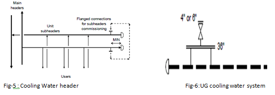
If the CW network is located underground with large headers size, manholes (36”, 900 mm diameter) are required for the inspection and maintenance of pipes. Manholes are normally placed close to the beginning and to the end of each header and sub-header and along with the headers at a fixed distance (every 200-300 meters) according to contractual requirements. A manhole can be provided with an additional 4” or 6” valves on top, to permit venting during start-up (Figure 6). A note will be added on P&IDs.
Flow control of cooling water:
As a result of CW circuit verification, some cooling water users could receive less water than required. Other users, instead, receive a flow rate higher than required. Therefore an adjustment of the water distribution is necessary. Some users can have their own control valve on the cooling water side, in order to regulate the CW flow as required by the different working conditions. CW users without a control valve may have manually adjustable piping valves (butterfly type), on the inlet and outlet line to throttle the flow when required (Figure 7).
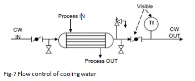
The valve to be throttled is the one provided on the outlet line, close to the temperature indicator. If necessary, also a valve on the inlet line can be used.
Cooling water users with control valves
A control valve on the CW side of a single user is used to regulate the CW flow. Control valves shall be installed only if necessary when big differences among consumptions cases of H&MB are expected, i.e. when a precise adjustment of the duty is required. Examples are amine trim coolers, vacuum packages, columns overhead condensers, and cycle gas coolers. Column overheads are often critical because too much cooling duty could bring the column under vacuum conditions due to excessive condensation.
The valve controller is often a temperature transmitter located on the process outlet side of the exchanger. Throttling directly the CW flow in line can compromise the fluid dynamic of the circuit, above all if the consumption is high, compared to the pump design flow. On the other hand, if one case of H&MB uses a very low flow rate, large lines with low flow suffer from solid deposition due to low velocity. Also, CW return temperature higher than the acceptable limit could be originated emphasizing the above effects. In this case, it is better to install a bypass line around the user and to divert a part of the fluid towards the bypass, regulating CW through the exchanger, without decreasing the total flow in the lines. This measure avoids also low-velocity problems. The bypass can be sized for the total flow, in case a shutdown of the item is foreseen without complete closure of the lines with trapped water inside. Otherwise, the bypass line will be sized for the flow difference between higher and lower consumption cases.
Two configurations are possible:
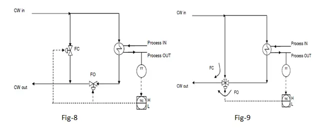
Fig-9: One three-way valve on the outlet side of the exchanger, to make Cooling water mixing easier
The failure position of the valves shall be always selected in order to let the CW flow through the exchanger,
in order not to have CW failure. For a column overhead condenser, pay attention to the possible vacuum condition, when the failure position is open. Fail Last position (FLO, or stay-put) could be preferred.
Cooling Water System Control
Cooling water pumps normally do not have control valves on the discharge line. There is no need to set a flow through the main header; the only requirement is to provide the necessary cooling water flow for each user.
Even the pressure is not normally regulated; it depends on the network fluid dynamic and on the return point pressure.
For the pump minimum flow line, It has to be evaluated if a stop-check valve on the discharge of the pump has to be installed; this valve facilitates start, stop, and avoids surge events due to rapid check valve closure time during an emergency shutdown. This valve shall be added to the pump Vendor’s scope of supply. A note on the pump datasheet and P&ID should be added, for example: “Non-return valve complete with power actuator, auto-closure control, hand operating gear, position indicator, and terminal box. Supplied by pump Vendor.” This non-return valve normally acts as an isolation valve too; if required by the Client, another isolation valve can be added downstream (Figure 10). As an alternative to the integrated stop-check valve which combines two functions, it is possible to consider the solution that consists of the provision of an independent check valve (dual flap-type) and a motorized valve.
Automatic start-up of the spare pump shall be provided to overcome the temporary partial lack of CW when an operating pump has a failure. Start-up should be provided with a low-low pressure actuation, more often than a flow actuation; this is to avoid starting off the spare pump during a blocked outlet condition, with zero flow and high pressure. Pump start-up will be specified with the discharge valve closed only if the stop check valve is present downstream.
Dear Sir,
I have a question. We have a Industrial machines cooling water circulation. It is cooling the Gear Box Oil, bearings etc. The return water will be 3-5 Deg C more than Cooling Water. We want to have a underground tank with open water surface and a shed over it to prevent dust . We do not intend using a Cooling tower for this small temperature differential. Flow rate is 32 M3/Hr max for cooling 5 to 6 different units. The cooling water is fully recirculated. a) Should we consider about 5% as evaporation Loss from Water to surface of the Tank ? That means 1.6 M3/Hr is the makeup water. In that case what should be the Top surface Area of water in tank and what should be the tank Capacity?
Hi,
A water cooler heat exchanger, located on a 20 m high structural platform. Water header is located u/g. What precaution do you take, in case of Pressure loss in cooling water header?
Thank you for this very informative description of pcw design. I wanted to know about materials. What materials should be used for PCW S & R? (And why)
Thank you
What are the best practices for installation when tying into a central PCW system that’s already pressurized with water and already flushed.