
Many a time during our day-to-day engineering services we need to calculate several important dimensions from the Nozzle Orientation drawing (Part of the Equipment GA drawing) of the pressure vessel. This article will provide a sample case study for distance calculation between the center lines of the Dish and Nozzle from the Pressure Vessel Nozzle Orientation Drawing. Before starting the calculation, we need to know the different types of Dishes used for the pressure vessel and the terms related to it.
Types of Pressure Vessel Dishes
There are mainly three types of Dishes used for pressure vessels–
- Tori-spherical
- Ellipsoidal
- Hemispherical
1. Tori-spherical Dish –
It is also called Tori-spherical Head or Ends. This dish is used for both horizontal and vertical both types of vessel, which is used to store liquids and gasses, with a pressure range of 0.2 N/mm2 to 1.5 N/mm2.
Crown Radius (CR) for Tori-Spherical Dish is equal to the Inside Diameter (ID) of the shell/dish. The Knuckle Radius is between 6% to 10% of the Inside Diameter (ID) of the shell/dish and the Straight Face (SF) is between 10mm to 30mm depending upon the thickness of the shell/dish.
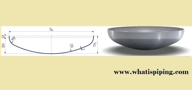
Crown Radius, Knuckle Radius, and Straight Face
Refer to Fig. 2 below.
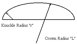
- Crown Radius (CR)- The radius of the sphere is called the crown radius (radius with reference to the shell).
- Knuckle Radius (KR)- The radius of the torus is called the knuckle radius (radius with reference to the dish).
- Straight Face (SF)- The straight face is normally considered 3.5 times the thickness of the shell/dish.
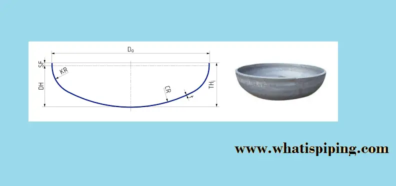
2. Ellipsoidal Dish-
It is also called Ellipsoidal Head or Ends. It is comparatively deeper than a Tori-spherical dish and therefore able to resist higher pressures. This is costlier to form than a Tori-spherical dish and the pressure range is above 1.5 N/mm2.
Crown Radius (CR) for Ellipsoidal Dish is 0.9 times the Inside Diameter (ID) of the shell/dish and Knuckle Radius (KR) is 0.177 times the Inside Diameter (ID) of the shell/dish.
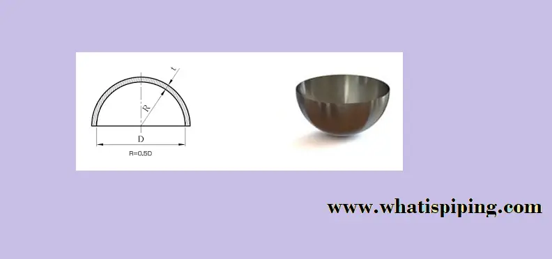
3. Hemispherical Dish-
It is also called Hemispherical Head or Ends. It is clear from the name that this type of dish is a Hemisphere with throughout constant radius. This type of dish is used for a high-pressure application, which is of higher thickness, therefore not preferred where space is less. It does not consist of Crown Radius (CR) and Knuckle Radius (KR) but, is replaced with the Radius (R) I; e 0.5 times the Inside Diameter (ID) of the shell/dish.
Formulas required for calculation
| Dish type | Crown Radius(CR) | Knuckle Radius(KR) | Dish Height |
|---|---|---|---|
| Tori-spherical | = ID | 0.06*ID 0.1*ID (mostly used) 0.16*ID | 0.194*ID |
| Ellipsoidal | 0.9*ID | 0.177*ID | 0.25*ID |
| Hemispherical | 0.5*ID | 0.5*ID | 0.5*ID |
Notes:
1. For Hemispherical, crown and knuckle radius will be replaced with Constant Radius(R).
2. ID means the Inside Diameter of the dish/shell.
Input from Client
| Case No. | Dish Type | Inside Diameter(ID) in mm | Thickness of Dish | Nozzle Size | Nozzle Projection in mm | Nozzle Type | Rating |
|---|---|---|---|---|---|---|---|
| 1. | Tori-spherical | 3000 | 20 | 6″ | 200 | WN | 150# |
| 2. | Ellipsoidal | 4500 | 25 | 8″ | 200 | WN | 150# |
| 3. | Hemispherical | 8500 | 35 | 2″ | 150 | WN | 150# |
Steps for Calculation
Step-1. Draw the free-hand cross-section drawing of the shell and dish as drawn in figure no. 5
Note: We are solving case no. 1, refer to table no. 2
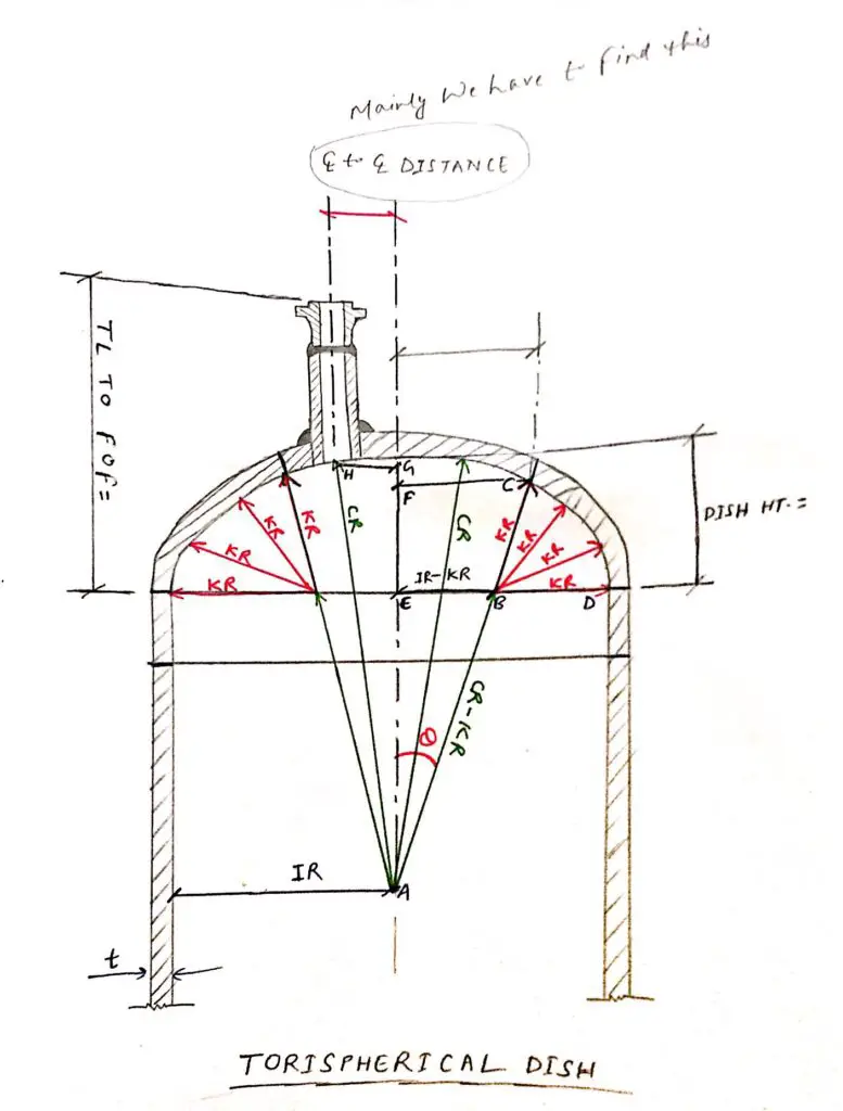
Step-2. Finding CR-KR, IR-KR, and Dish Height (refer figure no. 5 for each step).
We know from the formula,
CR=ID=3000 mm
KR=0.1*ID=0.1*3000=300 mm
Dish Height=0.194*ID=0.194=3000=582 mm
So,
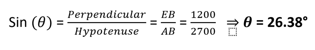
CR-KR (Distance AB) = 3000-300=2700 mm
IR-KR (Distance EB) = 1500-300=1200 mm
Step-3. Finding Ɵ![]()
![]() using the Pythagoras theorem
using the Pythagoras theorem
Step-4. Finding Distance FC using the Pythagoras theorem.

Step-5. Calculation of the center-line distance
Now, we can get the Distance between the CL of Nozzle and to CL of Shell as follows:

So,
CL to CL Distance = 1333 – (84+25) = 1224 mm
Note- This is the minimum distance required for Installing Nozzle for this particular case. Similarly, we can calculate the distance for different sizes of nozzles and for other Heads.
Step-6. Calculate the Distance between the Tangent Line(TL) of the Dish to the Face of the Flange (FOF)
It is also an important dimension for Nozzle Orientation Drawings.
TL to FOF Distance = Nozzle Projection + Thickness of Dish + Distance EG
Note- a. Check the Projection of the Nozzle in Databook or Equipment MDS.
b. Thickness is given in Table no.- 2.
C. Distance EG needs to calculate Using the Pythagoras theorem.
EG= AG-AE
So,
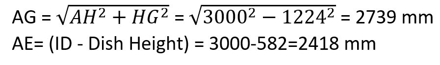
Hence, EG=2739-2418=321 mm
Therefore, TL to FOF Distance = 200+20+321 = 541 mm
Important Note- These are the dimensions that will be constant, But the Angle Projection can be any as per the requirements of the project.
Few more related resources for you..
A short Presentation on Basics of Pressure Vessels
Brief Explanation of Major Pressure Vessel Parts
10 points to keep in mind while using project-specific pressure vessel nozzle load tables during stress analysis.
Understanding Pressure and Temperature in the context of Pressure Vessel Design
A Presentation on Vessel Clips or Vessel Cleats
Few Articles related to Heat Exchanger BasicsOnline Course on Pressure Vessels
If you wish to learn more about Pressure Vessels, their design, fabrication, installation, etc in depth, then the following online courses will surely help you:
Great job rehan. Keep it up. Really Very useful for the piping engineers.
Dish me nozzle ka distance diya hai Arc distance kaise nikale
DISH H = 582mm
AND
TL to FOF Distance = 541 mm
UHmmmmm … pls chk ?!
Hello,dear friend,I’m selena,we are a professional supplier of pressure vessel head,are you interested?