
A gas turbine is a rotary machine in which the chemical energy of the fuel is converted into mechanical energy or kinetic energy in terms of shaft power. In other words, it is a mechanical power or thrust-delivering machine. It uses a gaseous working fluid for this purpose. The generated mechanical power can be used by industrial devices. There is a continuous flow of the working fluid in a gas turbine. Power generation gas turbines are the ones that produce shaft power. To propel an aircraft, gas turbines are used that convert fuel energy into kinetic energy for the generation of thrust. Fig. 1 below shows a typical representation of a Gas turbine.
Applications of a gas turbine
Major applications of gas turbines are found in:
- As the direct and mechanical drive for various industries
- Aviation
- Electrical Power generation
- Oil and gas industry
- Marine propulsion
- Turbo generators
- Turbo-compressor
- Automotive sector
Working principle of a gas turbine
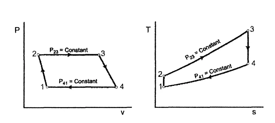
The working of a gas turbine is based on the thermodynamic Brayton Cycle. The Brayton cycle consists of two adiabatic work transfers and two constant pressure heat transfer heat processes (Fig 2). The gas undergoes an isentropic, adiabatic compression in State 1 to State 2. This process increases the temperature, pressure, and density of the gas. Next, heat is added at constant pressure in State 2 to State 3. For a gas turbine, a combustion process adds heat. During State 3 to State 4, the gas passes through an adiabatic isentropic turbine that decreases the temperature and pressure of the gas. In the case of a closed gas turbine Brayton cycle, heat is removed from the gas between State 4 and State 1 via a heat exchanger.
Let’s understand the basic operating principle of a gas turbine with the following example:
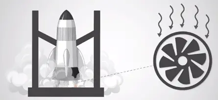
Imagine there is a rocket in which fuel is going to burn thereby creating high-pressure exhaust gas. According to energy conservation law, in high-pressure exhaust gas, the chemical energy of the fuel is converted into mechanical energy. The thrust of the exhaust gas tries to move the rocket forward when the rocket is fired. Now the question is if one fixes the rocket body with a mechanical structure in order to prevent its movement. What will happen?
In such a case, the high-pressure exhaust gas releases but in a backward direction. Now another case is that what if we add a set of turbine blades to this back-fired exhaust gas?
The released mechanical energy which is in the linear backward direction will transform into rotational movement of the turbine shaft which is a big success. This means the chemical energy of the fuel gas is transformed into rotational mechanical energy of the turbine shaft as shown in Fig. 3.
In simple words, in a gas turbine, hot gases move through a multistage gas turbine. It has both stationary and moving blades just like a steam turbine. The stationary blades adjust their velocity and guide the moving gases to the rotor blades. The turbine’s shaft is coupled to a generator.
The working principle of a gas turbine in a power plant is as follows:
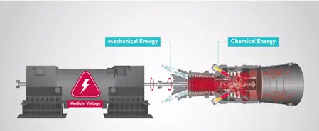
In a gas turbine power plant, there is a generator known as an electrical machine and this generator needs a prime mover which is a gas turbine in order to generate electricity as shown in Fig. 4.
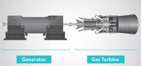
It transforms the fuel’s chemical energy into mechanical energy or in other words converting natural gas into mechanical energy. The generated mechanical energy is then transferred to the generator’s shaft through a gearbox. Now the turbine can create electrical energy as shown in Fig. 5.
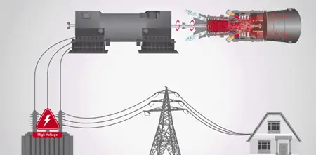
This prime form of electrical energy usually has a low or medium level of voltage. In order to manage power loss in transmission lines, step-up transformers are used to increase this voltage and the increased voltage is provided to the electrical energy which in turn is transmitted through the transmission lines and delivered to the grid as shown in the below Fig. 6.
Working principle of a gas turbine in the oil and gas industry
A few points mentioned below should be kept in mind like:
- For the oil and gas production process, the turbine is coupled to a compressor or a pump instead of coupling with a turbine.
- An arrangement similar to a steam turbine is considered when one uses a gas turbine to drive a compressor.
- The header tanks and lube oil are required in the auxiliary piping system.
- The exhaust system should be considered which has ducting to a few heat recovery systems, that is, a process heater or a steam raising plant.
- There should be a provision for the maintenance and operation of all machinery.
- Outside the compressor house, combustion air must be taken to the turbine burner from a safe location. The most likely required items are an inlet silencer and filter.
Components of a gas turbine
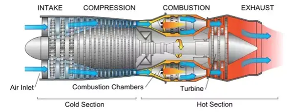
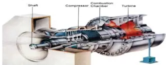
Gas turbines have three main parts as mentioned below in Fig. 7:
- Air compressor
- Combustion chamber
- Turbine
Air Compressor:
With the combustion chamber between the air compressor and turbine, both the air compressor and turbine are mounted on either end on a common shaft. Gas turbines require a starting motor as they are not self-starting. The use of an air compressor is to suck the air and compress it thereby increasing its pressure. Axial design type compressors (multi-stage) are preferred for the most advanced and large gas turbines.
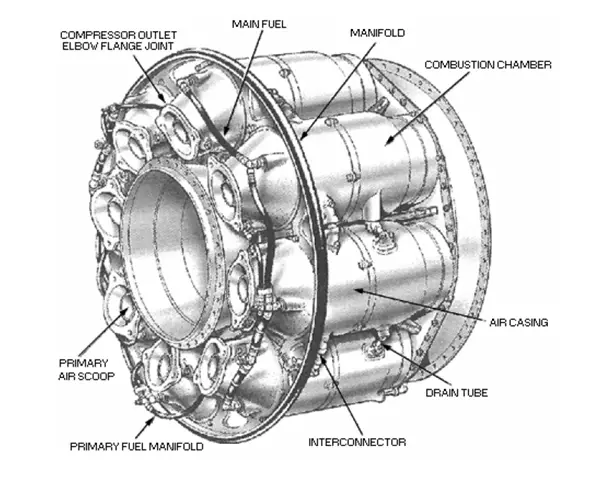
Combustion chamber:
Here the compressed air is combined with fuel and the resulting fuel-air mixture is burnt and delivers the combustion products to the gas turbine. With the high pressure of air, the fuel mixture burns quite well. Nowadays liquid fuel, gaseous fuel, or natural gas is used in gas turbines. Generally, three types of combustion chambers are used:
- annular combustor chambers
- can (multi-can) combustor chambers
- can-annular combustor chambers
Fuel is injected at the upstream end of the burner in the form of a highly atomized spray. Fuel nozzles may be a simplex type or dual fuel type. Some gas turbines are “bi-fuel” which means they have to ability to burn a mixture of gas and liquid fuel.
Turbine:
There is a multistage gas turbine from where hot gases move and the kinetic energy is transformed into shaft horsepower. A gas turbine has both stationary and moving blades just like a steam turbine. The purpose of stationary blades is to guide the moving gases to the rotor blades and then adjust their velocity. The turbine’s shaft is coupled to a generator.
Exhaust Module:
The hot gases from a gas turbine exit through the exhaust section. The exhaust case consists of an inner and outer housing.
Other gas turbine parts are
- Cooling system
- Bearing and Lubrication system
- Fuel system, etc
Types of gas turbine
The below listed are types of gas turbines:
- Open-cycle gas turbine
- Closed-cycle gas turbine
- Aero derivative gas turbine
- Scale jet engines
- Auxiliary power unit
- Jet engines
Open-cycle gas turbine
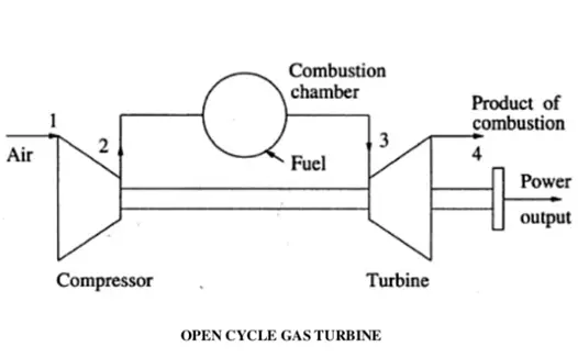
Open cycle gas turbine consists of three parts mainly a combustion chamber, turbine, and compressor. The compressor raises the pressure by taking in the ambient air. Fuel is burnt to add heat to the air in the combustion chamber thereby raising its temperature. The heated gases from the combustion chamber are then passed to the turbine where it does its mechanical work while expanding. The below figure (Fig. 10) shows an image of an open-cycle gas turbine.
Closed cycle gas turbine:
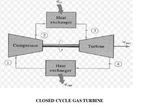
The working fluid used in a closed-cycle gas turbine is air or any other suitable medium that comes out from a compressor and is heated in a heater by some external source at a relatively constant pressure. The heated high-pressure and high-temperature air is then passed to the turbine. The fluid from the turbine is then cooled to its original temperature by some external cooling agent and then passed to the compressor. This way the working fluid is constantly used in the system and the required heat is given to the fluid by the heat exchanger without significant change in its phase. The below figure (Fig. 11) shows an image of a closed-cycle gas turbine.
Aero derivatives gas turbine:
- These types of gas turbines are used in electrical power generation because of their ability to handle load changes more quickly and the ability to shut down better than industrial machines.
- These are also used in the marine industry in order to reduce weight.
Scale jet engines:
- These are also known as miniature gas turbines.
- The scale jet engines have the ability to produce up to 22 Newton’s of thrust and can be easily built by most of minded mechanical engineers with basic engineering tools such as a metal lathe.
Auxiliary gas turbine:
These are smaller types of gas turbines used to supply auxiliary power to aircraft. Auxiliary gas turbines are used to supply air conditioning and ventilation. They supply compressed air power to jet engines. They also supply mechanical power to the gearbox to start larger jet engines or to drive shafted accessories.
Design of a gas turbine
The factors that limit the size and efficiency of a gas turbine are the firing temperature, compression ratio, mass flow, and centrifugal stresses.
The most critical areas in the gas turbine design that determines the engine
efficiency and life are the hot gas path, i.e., the combustion chambers and the turbine first stage stationary nozzles, and rotating buckets. The components in these areas represent roughly 2% of the total cost of the gas turbine, but they control the gas turbine output and efficiency.
Nickel superalloys are normally used for gas turbine nozzles and buckets. These are coated under a vacuum with special metals (platinum-chromium-aluminide) to protect against the hot corrosion occurring at high temperatures in presence of contaminants like sodium, vanadium, and potassium.
The operating performance of gas turbines can be increased by the continuing improvements in firing temperatures and compression ratios. Air-cooled nozzles and buckets using bleed air from the compressor are major advancements to increase the firing temperature. This limits the metal temperatures of the nozzles and buckets to withstand hot corrosion and creep.
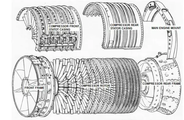
To provide additional turbine power output by increasing the Final compressor pressure, additional compressor stages can be added to the compressor rotor assembly to give a higher compression ratio.
Natural gas, diesel oil, residual or crude oil can be used as gas turbine fuel.
With an increase in ambient temperature and altitude, the air density reduces. This causes a significant reduction in the power output and efficiency of the gas turbine. Ambient air temperature and elevation changes do not affect steam plants and diesel.
Codes and Standards
Frequently used codes and standards that govern the design, construction, testing, etc of a gas turbine are
- API 616
- ASME PTC 22
- ISO 2314
- ISO 3977
- ISO 11086
- ISO 7919
- ISO 10494
- ISO 11042
- ISO 21789
- ASME 133
- NFPA 37
- IEC 60034
- ISO 19859
Gas turbine performance
The factors that impact the performance of a gas turbine are
- Inlet air density
- Ambient air temperature
- Altitude and ambient pressure
- Humidity
- Inlet and exhaust pressure losses
- Number of shafts
Advantages of a gas turbine
- Fuel storage requires less area and handling is easy.
- The maintenance cost is less.
- Construction is quite simple.
- Compared to steam power plants, it does not require a condenser, boiler, or other accessories.
- Fuels such as kerosene, benzene, paraffin, and powdered coal can be used which are cheaper than other petrol and diesel.
- In the areas of water scarcity, gas turbines can be used.
- It creates less pollution.
- It requires less amount of water.
Disadvantages of a gas turbine
- Most of the developed power is used to drive the compressor.
- This is the reason that a gas turbine has low thermal efficiency.
- High-frequency noise comes from the compressor which is again questionable.
- For various parts of the turbine, special metals and alloys are used because the running speed of the turbine is 40000 to 100000 rpm and the operating temperature is 1100 to 1260 degrees Celsius.
Gas turbine manufacturers
The major share of gas turbine manufacturing is controlled by the following organizations:
- General Electric (US)
- Siemens (Germany)
- Mitsubishi Hitachi Power Systems (Japan)
- Ansaldo STS (Italy)
- Solar Turbines (U.S.)
- Kawasaki Heavy Industries, Ltd (Japan)
- Doosan Heavy Industries & Construction (South Korea)
- Bharat Heavy Electrical Limited (India)
- OPRA Turbines (The Netherlands)
- Vericor Power Systems LLC (U.S.)
- Rolls-Royce (U.K)
The first three companies in the above list combinedly control more than 80% of the gas turbine market share.
Gas turbine vs steam turbine
The main differences between a gas turbine and a steam turbine are listed in the following table:
| Parameter | Gas turbine | Steam turbine |
| Working fluid | The gas turbine uses air or gas as the working fluid | Steam is the working fluid in the steam turbine |
| Thermodynamic Cycle | Brayton Cycle | Rankine Cycle |
| Power generation | Gas turbines are powered by the combustion reaction | Expanding steam provides power to the steam turbine |
| Efficiency | Comparatively higher than steam turbines | Lower than gas turbines |
| Operating temperature | Much higher | Lower |
| Installation Space requirement | Lower | Higher |
| Output | Torque or thrust | Torque |
| Cost | The maintenance and installation cost of a gas turbine is comparatively less | Higher |
| Startup and Control | Easy and quick | Difficult and time taking |
| Main components | Compressor, combustion chamber, turbine. | Steam turbine, boilers, pumps, heat exchangers, condensers. |
| Versatility | More versatile with respect to input fuel and application | Less versatile. |
Online Video Courses on Gas Turbines
To learn more about gas turbines click on the below-mentioned subjects, review the course and enroll:
Very impressive