
Heat Tracing of Piping Systems
Pipe Heat Tracing is a generalized term relating to the application of radiant heat input to piping systems from tubing attached to the outside of the pipe. Heat tracing is a process requirement. Pipes carrying higher fluid temperatures than the ambient temperature will lose temperature to the surrounding. Insulation is a way to reduce this loss. But insulation is not 100% foolproof. So to make up for that heat loss, small-bore steam pipes or electrical wires (known as heat tracers) are attached to the parent pipe. This system is called the heat tracing of piping.
Purpose of Heat Tracing
Heat tracing serves various other purposes as listed below:
- Maintaining the required temperature for the process fluid.
- Freeze protection.
- Maintaining the fluid viscosity.
- Snow and Ice Prevention, etc.
Types of Pipe Heat tracing / Heat tracing types
Heat tracing can be grouped into two classes:
- Fluid Heat Tracing or Steam Tracing and
- Electric Tracing
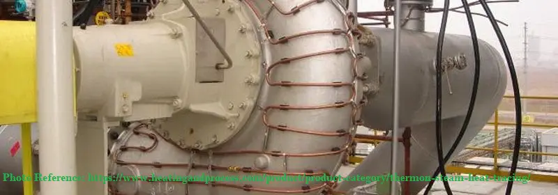
Steam Tracing
In Steam tracing (Fig. 1) of piping, steam is circulated through tubes that run alongside the pipes to keep the process fluid at the desired temperature. Other fluids like organics, glycols, etc can be used as tracing fluid in heat tracing system design. However, there are various advantages of using steam as heat tracing fluid as mentioned below:
- The cost of steam generation is less as compared to other fluids. So steam tracing is economical.
- The maintenance cost is also low. Once, the steam tracing network is installed, less maintenance costs will be involved.
- Steam tracing of piping is highly energy efficient.
- Pipe Steam tracing heats up the process fluid quickly.
- No pumping is required for steam.
- Temperature control in steam tracing is high.
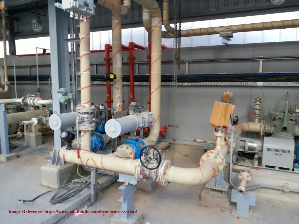
Electrical tracing
On the other hand, in electric tracing (Fig. 2) of the piping system, an electrical heating element transfers heat into the process fluid while running in physical contact along the pipe length. Heat is normally generated in an electrically resistive element. However, other effects like impedance, induction, skin conduction, etc can be utilized in electrical tracing. Electrical heat tracing is also known as cable heat tracing.
Pipe Heat Tracing Cable
Appropriate heat tracing cable for electrical tracing is determined based on the following parameters:
- Heat requirement.
- Ambient temperature.
- Pipe Material.
- Maximum Exposure and Maintenance temperature.
- Tolerance on supply voltage and voltage drop on feeding cables
- Service voltage.
- Area Classification.
- Chemical Environment.
- Design Margin.
Three types of pipe heat tracing cables are used for industrial electrical tracing systems. They are:
- Self-regulating polymer jacketed cables: These heat trace cables are suitable for temperatures up to 200°C and circuit lengths of up to 750 feet.
- Mineral insulated heat trace cables: Such heat tracing cables are used for a temperature of up to 650°C and circuit lengths of up to 3,300 feet.
- Skin effect heating system cables: For moderate temperature ranges and much longer heating circuits, skin effect heat trace cables are used. They can be used up to 82,000 feet (25 km) in length and their rated temperature is up to 250°C.
Controlling heat tracing temperature for electrical tracing is very important. Various control panels are used for heat tracing temperature control. The heat tracing system shall be suitable for operation on 240V + 5%, 50 Hz, single-phase AC supply. The Power supply to the heater tapes/heat tracing cables shall be from local distribution panels (LDPs) located in the field at strategic locations /load centers to be decided by the
contractor. However, the main Power Distribution Panel shall be located in Switchgear Room in a safe area.
Piping Heat Tracing tapes / Heating Tapes
Heat tracing cables are also known as heat tracing tapes. Industrial heat tracing tapes or heating tapes should possess the following characteristics:
- Heat tracing tapes should easily wrap around the pipe or equipment.
- Heating tapes should provide intimate contact with the pipe material for higher efficiency of heat transfer.
- Heat tracing tapes should be fast in heating up.
- Heating Tapes should be able to withstand higher required temperatures.
- Heat tracing tapes or heat tracing cables must be durable and long-lasting
Additionally, the heating tapes should possess the following features:
- To prevent damage during over-lapping, the heating tapes shall have a burn-out-proof feature.
- The heating tapes shall be suitable for use in the area defined in the process datasheets. Corrosion-resistant metallic braid must be provided for safe and hazardous area applications.
- In hazardous area applications, the surface temperature of the heating tapes shall not exceed 200 deg. C.
- For valves, flanges, pipe supports, and similar heat sinks, an extra heater tape length shall be provided. The heater tapes to be installed should consider easy maintenance or removal of the valve, and pipe support.
- Heat tape surfaces must be cleaned before the installation of heater tapes on pipes and other equipment.
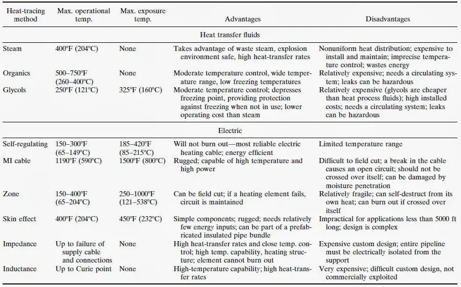
Advantages and Disadvantages of Piping Heat Tracing using Fluids or Electricity
The following figure shows the principal features of different types of heat tracing methods.
When Heat tracing is used to ensure that the system functions from a process standpoint regardless of climate conditions it is known as Process Control Tracing
Again when Heat tracing is used to prevent freeze-up due to climatic conditions only it is known as Winterization Tracing.
Heat tracing Design Steps
The following steps are followed for designing a pipe heat tracing system:
- Calculation of heat loss from the pipe or equipment.
- Adjust the heat loss for the insulation system.
- Correct that heat loss considering wind speed and additional safety factor (margin).
- So this calculated value will be used as input for heat tracing system design. The heat tracing system should add at least that much heat to the piping system to maintain the required heat (temperature) in the process fluid.
General Requirements for Piping Heat Tracing
General rules for Steam Tracing
- Steam tracing supply lines shall be taken from the top of the supply header to assure dry-quality steam.
- Identify the locations for steam tracing supply manifolds and condensate manifolds early in design to reserve space in plant layout. This applies to non-steam supply and returns manifolds (hot oil, glycol, etc.).
- Allow for an increase in insulation sizing to allow for tracers.
Instrument Application for heat tracing
In-line instruments can also be required to be heat traced as process condition dictates. In that case, Piping needs to provide steam supply and condensate collection manifolds for all other instruments. The break between Piping Traced Instruments and Control Systems traced instruments will match the drawing break between the two departments.
Heat Tracing System Description
Using various media such as steam, hot water, glycol, or hot oil heat tracing is installed to protect the piping, equipment, and instruments against temperatures that would cause congealing or freezing of the process fluids, interfere with operation, or cause damage to the equipment.
Heat Tracing Design Requirements
The daily average low temperature of the coldest month shall be used to select the low ambient design temperature that then determines the degree of winterizing protection required.
No winterizing is required for water service except where a sustained temperature below minus 1 degree C is often recorded for 24 hours or longer.
Compressors, blowers, and other mechanical equipment shall be specified for operation at low ambient design temperatures.
Heat Conservation while Heat tracing
Where feasible, insulation shall be used for heat conservation. Heat tracing, plus insulation, is the alternative method for heat conservation.
Heat transfer cement may be utilized when a process line requires a high heat input and common methods of heat tracing are inadequate.
Steam jacketing is utilized in specific cases where steam tracing with heat transfer cement is inadequate.
Electric tracing is utilized when precise temperature control is required or where steam tracing is not practical. The thermostat setting for electric tracing should not be higher than the fluid operating temperature.
Methods for Winterization
Winterizing by circulation shall be provided where a sufficient power source is available to keep the fluid circulating.
Utility water and utility airlines in intermittent service shall be winterized by draining.
Winterizing by steam tracing is the preferred method when winterizing by circulation and draining is impracticable.
Winterizing by electric tracing is utilized when precise temperature control is required or where steam tracing is not practical. The thermostat setting for electric tracing should not be higher than the fluid operating temperature.
The minimum tracing steam pressure shall be 1 Bar; the maximum required is 10.3 Bar. At minimum pressure, condensate shall be routed to the plant sewer system. If condensate is collected, the minimum usable pressure shall be 1.7 Bar.
Heat Tracer Description
Pipe Tracer Size and Length
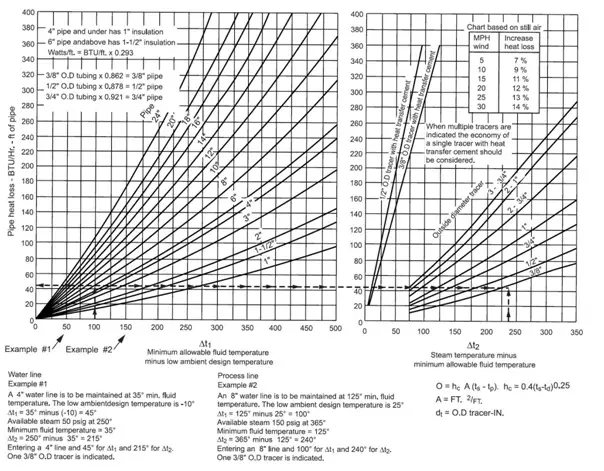
Required tracer size shall be determined by piping heat loss and tracer steam pressure found in the Heat Loss Chart (Fig. 1)
The minimum tracer size shall be 3/8 of an inch OD tubing; the maximum size shall be 1 inch OD tubing. For the economy, where Heat Loss Chart indicates the requirements for multiple tracers, a single tracer with heat transfer cement shall be considered.
When using heat transfer cement, tracers of 3/8 of an inch and 1/2 of an inch OD tubing are recommended. If more tracer area is required, multiple tracers of 3/8 of an inch and 1/2 of an inch shall be used.
Maximum tracer length shall be based on tracer size and steam pressure as follows:
Steam pressure 1 Bar through 1.7 Bar
- 60m for 3/8 of an inch and 1/2 of an inch tracers
- 100m for 3/4 of an inch and 1-inch tracers
Steam pressure 3.5 Bar through 13.8 Bar
- 60m for 3/8 of an inch and 1/2 of an inch tracers
- 120m for 3/4 of an inch and 1-inch tracers
Tracer lengths for Heat tracing with heat transfer cement shall be based on the recommendation of the manufacturer.
- For stainless steel lines, the tracer material shall be low-carbon steel. Stainless steel instrument leads shall be traced with copper tubing.
- Each tracer shall have its own trap. Tracer traps shall discharge to the sewer. If condensate must be collected, the minimum usable pressure is 1.7 Bar.
- Compression-type fittings shall be installed outside of the insulation OD.
- Socket-type fittings may be installed inside the insulation.
- The steam tracers shall be pressure tested before the insulation is applied. Under emergency conditions, the insulation may be applied but the fittings shall be left exposed until the testing is complete.
Heat Tracer Pocket Depth
- Pocket depth is the distance the tracer rises in the direction of flow from a low point to a high point. The total pocket depth is the sum of all risers of the tracer.
- The maximum tracer total pocket depth shall be equal to 40 percent of tracing steam gage pressure expressed in meters.
Example: Tracing steam 10.3 bar 30 m x 0.40 = 12 m feet total pocket depth
Tubing used for steam tracing/heat tracing
Steam tracing tubing materials shall be in accordance with material specifications.
Tracers shall be OD tubing. Soft annealed copper tubing shall be used where the temperature of the product line or tracing steam does not exceed 204 °C. Above this temperature, dead-soft annealed hydraulic quality, low carbon, seamless steel tubing shall be used where the temperature of the product line or tracing steam does not exceed 399 °C.
For aluminum pipelines, carbon steel tracer material shall not be used.
For aluminum pipelines and all lines above 399 °C, the tracer material shall be stainless steel.
For conditions where the tracer could overheat lines containing acid, caustic, amine, phenolic water, or other chemicals, insulation spacer blocks shall be installed between the tracer and the pipe.
hi,
I fortunately find your web site, during surfing the net to find out how to design the tracer system.
I ‘m not capable to find a reference.
I’d appreciate, if you can help me by more explanation and the way of finding how to make the abovementioned chart.
references are so much important for me.
In addition, what if we receive a point in diagram #2, which didn’t coincide a curve, while using the chart.
(for instance if we have a 100 degree difference, and 100heat loss for a 24″ pipe, what should we do and how can we decide?)
thanks in advance for your help
R.F
New Heat Trace tie from Panduit designed to quickly secure Heat Trace to pipes.
You tube video https://youtu.be/4OQZTvtaQ0s
Although electrical tracing can be employed for reasonably tight temperature regulation, the claim that is superior to steam depends on perspective on what “tight” means.
When setting a maximum temperature that is close to the maintenance temperature (say 20 C or less), electrical is harder to apply. I have found that electrical tracing may not remain reliable without a higher quality of PM, is often harder for operators to troubleshoot, and more often than not cannot be within the temperature range throughout the length of the pipeline. There is no inherent limitation to electrical tracing applying too much power locally, away from the temperature controller. For example if the TE is in wet insulation or in a windy spot, full power may be called for, but overheat the rest of the line. Placement in another spot ends up with cold spots either from wind or wet insulation. One might try multiple lower wattage cables, but the cost advantage is lost too.
It would be informative to know if anyone has ever installed electrical heat maintenance on molten sulfur piping, and what they do five years later. (Molten sulfur piping is a well understood comparable use, and there many plants to survey.) Myself, I am only aware of steam-fed systems. Typically they are fully-jacketed, or using a mix of partially jacketed pipe, with clamp-on devices, to achieve sufficient surface coverage. Specifically they supplement with bolt-on heat-channels, and valves, flanges and irregular devices are encased in clamp-on jackets.
Regardless of the heat source, a small temperature requirement means being diligent in engineering out the paths that leak heat. E.G.:
* Use insulated pipe shoes, anchors and hangers.
* Forbid insulation coping.
* Dummy legs are insulated and heated, as if they contained process material.
* Sufficient coverage of the inherent cold spots, (valve stems, flanges)
* Insulation practices that are robust to water intrusion.
* As temperatures drop below 275 deg F, the condensate side configuration matters. One must route to limit condensate static head and limit circuit lengths to limit the end-to-end pressure difference.
All of the above is improved, if the process line routing to minimize pockets, as well as butt weld construction, limiting gaps between the tracing and the pipe.
Molten Sulfur line using Electric Tracing is common in plants. These applications inside the plants are either using Self regulating or Mineral Insulated Heat Tracing cables.
There are various longlines which have been installed using Electric heat tracing with Skin Effect Heat Tracing System (Which is normally installed for long pipelines). The oldest system as far as I recall is almost 30 years old is in Saudi Arabia for Berry Gas, which is more than 25 Km long. Qatar Gas using around 40 Km Sulfur line and subsequent additions for almost 14 years. ADNOC using almost 160 Km of Skin Effect System for Molten sulfur pipelines for almost 6 years. Saudi Aramco installed another molten sulfur pipeline around 16 Km with Skin Effect Heat Tracing System. There are many more pipeline which are currently being considered with Skin Effect Electric Heat Tracing.