Many a time during interfacing with other EPC organizations or vendors, Caesar II file transfer becomes a necessity to reduce re-modeling time. And most of the time it happens that the Caesar II versions do not match. The caesar files with the lower version (i.e., version 7.0) easily open in their higher version. But if the file received is of a higher version (i.e., version 8.0) then it’s difficult to open in the lower version. For opening such files into the lower version there is a trick. One has to follow the neutral file methodology for such activities. In this article, the procedure for opening a caesar II file version 8.0 into caesar II version 7.0 will be explained.
However, it’s not suggested to use a lower version of the software for a higher version file as due to changes in codes the results of both versions will be different. So the same situation must be handled with utmost care.
Neutral file Conversion
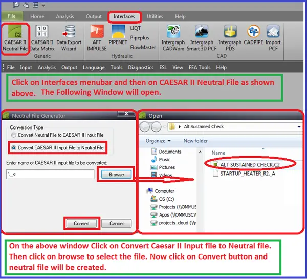
Ask the neutral file of the higher version from other contractor r vendors. The procedure for neutral file conversion is explained below in Fig. 1 and 2.
Fig. 1: Procedure for making Neutral file from caesar II file
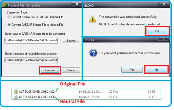
The Caesar II neutral file will be created in the same folder where the original file is stored. Refer to Fig. 2 to know the generated Neutral file.
Fig. 2: Neutral file in the same path as the original file.
Neutral file to Caesar II file conversion
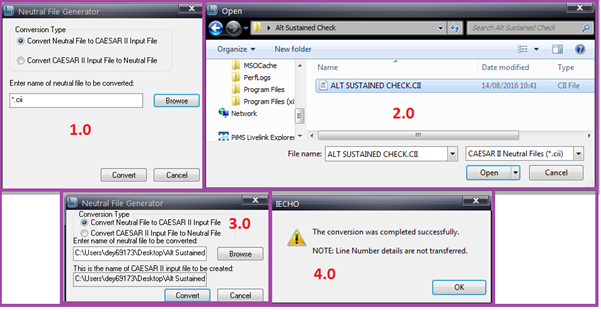
Once you possess the Neutral file of the higher version and saved it in some known path, Open the Caesar II lower version (7.0). In a similar way again go to Interfaces—-Caesar II neutral file—-Convert Neutral file to caesar II input file. And follow the steps mentioned in Fig. 3
Fig. 3: Generation of Caesar II file from Neutral file.
Now Caesar II file is ready to open in your version of the software. Note that the load cases you have to prepare them again.
The Caesar II version 2016 (8.0) file I could able to open in Version 2014 and Version 2013 R1 but it does not open on Version 2011 R1. It showed an error and the conversion could not succeed.
For some years, It was not possible to open upper-version C2 files into the lower versions. But again the feature is active in recent versions. Mostly after the completion of the Caesar II software takeover process by Hexagon, wherever a new version of Caesar II software is released by Hexagon their Caesar II files can be opened in the lower versions by following the above-mentioned method.
However, for opening a caesar file of version 12.0 into its lower version 11.0, neutral file conversion is not required. The caesar ii files of version 12 automatically open in caesar ii version 11 (2019).
Many of you are aware that the 2014 edition of ASME B 31.3 is scheduled to publish on 21st February 2015. Similar to every new edition this edition too contains several updates. Thanks to Mr. Don Frikken who has listed a few of the substantive changes in one of his blog posts. Here I am providing few major points. For details please read the complete article by clicking on the link provided at the bottom of this post.
In addition to the many clarifications, updated references to codes and standards, updates to basic allowable stresses, and added listed materials, there are several substantive changes to the 2014 Edition of ASME B31.3, Process Piping.
Some of these changes are listed below:
The definition of Category M Fluid Service is revised in the 2014 edition to provide better guidance on the selection of the Category M Fluid Service designation. As per the new edition of the code Category M Fluid Service is A fluid service in which all of the below-mentioned conditions apply:
The fluid is so highly toxic that a single exposure to a very small quantity of the fluid caused by leakage, can produce serious irreversible harm to persons on breathing or bodily contact, even when prompt restorative measures are taken; and
If after consideration of piping design, experience, service conditions, and location, the Owner determines that the requirements for Normal Fluid Service do not sufficiently provide the leak tightness required to protect personnel from exposure.
Flared laps are prohibited for use in Category M fluid service in the 2014 edition.
Because of the potential for misapplication of the alternative rules, and because many of the provisions of Appendix P had been incorporated into the base Code, Appendix P has been removed in the 2014 edition.
The 2014 edition explicitly requires that the maximum value of SL considering all conditions be used in calculating the allowable stress range.
The 2014 edition requires that thermo-wells need to comply with ASME PTC 19.3 TW.
The 2014 edition requires that when cold spring is used, the reactions be computed both with the assumption that only two-thirds of the design cold spring is present and with four-thirds of the design cold spring present.
The 2014 edition permits the hydro test pressure to be lowered to the design pressure while examining for leaks. The 2014 edition simplified the calculation of hydro test pressure.
The 2014 edition restricted the use of Fig. 323.2.2B to provide a further basis for the use of carbon steels without impact testing. The Code warns that the calculation of stresses due to cold springing or misalignment should be included as part of the stress ratio.
The 2014 edition added requirements for and illustrations of welds for integrally reinforced branch connections.
The 2014 edition revised the Preheat and Heat Treatment requirements somewhat. This revision, along with revisions to ASME B31.1, makes the preheat requirements in the two Codes the same.
The 2014 edition added specific examination personnel qualification requirements, which are those described in ASME B&PV Code, Section V.
The 2014 edition added specific acceptance criteria for magnetic particle and liquid penetrant examination.
The 2014 edition changed the leak test pressure from 1.5 times the design pressure corrected for temperature to 1.25 times the design pressure corrected for temperature.
In the world of piping engineering and fluid control systems, ball valves are a crucial component that plays a vital role in regulating the flow of liquids and gases. These valves are widely used in various industries, ranging from oil and gas to water treatment, due to their exceptional reliability, versatility, and ease of operation. This article provides everything you need to know from ball valve definition, types, parts, working, materials, end connections, specifications, advantages, and standards to testing and uses.
What is a Ball Valve?
A ball valve is a type of valve that uses a spherical perforated obstruction (a rotary ball) to stop and start the hydraulic flow. A ball valve is usually rotated 90° (quarter-turn valve) around its axis to open and close.It is one of the most widely used valve types. Ball Valves are suitable for both liquid and gas services. They are highly popular in the chemical, petrochemical, and oil and gas industry because of their long service life and reliable sealing throughout their service life. Ball valves can even be used for vacuum and cryogenic services. Developed around 1936, Ball valves are among the least expensive valves which are available in extremely wide size ranges.
Ball valves are sometimes used as control valves due to their cost-effectiveness but are not preferred as they don’t provide precise control and adjustments. The ball is positioned within a valve body, and a handle or actuator is used to rotate the ball either perpendicular or parallel to the flow direction, thus controlling the fluid flow. When the hole aligns with the flow direction, the valve is in the open position, allowing fluid to pass through. Conversely, rotating the ball to block the hole closes the valve, stopping the flow.
Applications of Ball Valves
Ball valves find application across a wide range of industries due to their versatility and ability to handle various types of fluids, from corrosive chemicals to high-pressure gases. Major applications of ball valves include
1. Use of Ball Valves in Refineries:
I have seen ball valves to be used as shut-off and isolation valves for tower bottom lines and thermal-cracking units; Gas/Oil separation lines, Gas distribution measuring, metering, and pressure regulation stations, Oil loading control stations, Pumping, and compressor stations, Emergency shut-down loops, Refining units, etc.
2. Use of Ball Valves in Chemical and Petrochemical Complexes:
Ball valves are used for low differential pressure control, emission control, and handling highly viscous fluids, and abrasive slurries in process and storage facilities. They are suitable for handling corrosive chemicals and hazardous materials, making them a preferred choice in chemical processing plants.
3. Power Industry Applications of Ball Valves:
For boiler feedwater control, such as burner trip valves, for control and shut-off for steam, etc.
4. Ball valves in Gas and Oil Production:
In subsea isolation and shut-down facilities, For oil-head isolation, pipeline surge control, processing separation, storage, transmission and distribution, secondary and enhanced oil recovery.
5. Use of ball valves in the Pulp and Paper Industry:
They are used as shut-off valves in pulp mill digesters, batch-digester blow service, liquor fill and circulation, lime mud flow control, dilution water control, etc.
6. Water Treatment:
Municipal water treatment plants utilize ball valves for controlling the flow of water in various processes, such as filtration, chlorination, and distribution.
7. HVAC Systems:
Heating, ventilation, and air conditioning systems use ball valves for regulating the flow of water and refrigerants in commercial and residential buildings.
8. Other uses of ball valves include
Food Industry
Marine and Solid transport
Water supply and transport
Manufacturing
Ball Valve Standards
Below-mentioned international Codes and Standards are used for Ball valve Design
Design Standard – API 6D / ISO 14313 / BS EN 17292/BS 5351/MSS SP 72
Testing Standard – API 6D / API 598 / BS 6755 Part I/MSS SP 61
Fire testing Standards – As per API 6FA, API 607, ISO 10497, or BS 6755 Part II.
Dimensional Standard – ASME B16.10 / API 6D
Parts of a Ball Valve
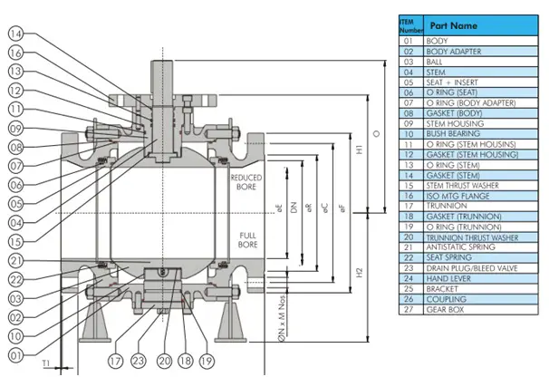
The housing, seats, ball, and lever for ball rotation are the major parts of a standard ball valve. Refer to Fig. 1 below which shows the internal parts of a ball valve.
Fig. 1: Ball Valve Parts
Ball valves are manufactured with the following crucial parts:
Valve Body:
The main part of a ball valve is the valve body which contains all of the internal components for on/off control.
Rotary Ball:
A ball with a center hole through which the media flows is the main characteristic of ball valves that differentiates these valves from other valve types. The hole of the ball through one axis connects the inlet to the outlet. The Stem controls the direction of the ball. The ball may be free-floating or trunnion-mounted. Trunnion-mounted ball valves reduce the operating torque to about 2/3rd that of the floating ball valves.
Stem:
The stem of a ball valve connects the ball to the external control mechanism.
Seats:
The seats of a ball valve are discs that lie in between the ball and the body. It provides the necessary seal between the two and also supports the ball.
Power Source:
A manual or actuated power source provides energy to the stem of the ball valve for rotating it. Manual actuation uses levers and handles, which the operator controls during requirements. Automatic actuators use electric, pneumatic, or hydraulic power sources.
Packing:
Packing is a seal around the stem to prevent the media escape.
Bonnet:
The bonnet is part of the ball valve body that contains the stem and packing.
The following video clearly shows the parts and working of ball valves using an animation.
Ball Valves: Parts and Working
Ball Valve Working Principle
A ball Valve is a rotary motion valve. When the stem (Item 04 in Fig. 1) transfers the motion to the connected ball (Item 03), the ball rotates. This ball of a ball valve is rested and supported by the ball valve seats (item 05). This rotation of the ball over valve seats allows the bore to open or close helping the fluid to flow or stop.
For manual ball valves with normal service, when the port opening of the ball is in line with the inlet and outlet ports, flow continues uninterrupted through the valve, undergoing a minimal pressure drop if a full-port ball is used. Obviously, the pressure drop increases with the use of a reduced-port ball. When the hand operator is placed parallel to the pipeline, the flow passages of the ball are in line with the flow passages of the body, allowing for full flow through the closure element. As the hand operator is turned to the closed position, the ball’s opening begins to move perpendicular to the flow stream with the edges of the port rotating through the seat. When the full quarter-turn is reached, the port is completely perpendicular to the flow stream, blocking the flow.
In throttling applications, where the ball is placed in a mid-turn position, the flow experiences a double pressure drop through the valve, similar to a plug valve. When a characterizable ball is used to provide a specific flow to position, as the ball is rotated from closed to open through the seat, a specific amount of port opening is exposed to the flow at a certain position, until 100 percent flow is reached at the full-open position.
As with all rotary-action valves, the ball valve strokes through a quarter-turn motion, with 0° as full-closed and 90° as full-open. The actuator can be built to provide this rotary motion, as is the case with a manual hand lever, or can transfer linear motion to rotary action using a linear actuator design with a transfer case.
When full-open, a full-port valve has minimal pressure loss and recovery as the flow moves through the valve. This is because the flow passageway is essentially the same diameter as the pipe inside diameter, and no restrictions, other than some geometrical variations at the orifices, are present to restrict the flow. The operation of throttling full-port valves should be understood as a two-stage pressure drop process. Because of the length of the bore through the ball, full-port valves have two orifices, one on the upstream side and the other on the downstream side. As the valve moves to a mid-stroke position, the flow moves through the first narrowed orifice, creating a pressure drop, and moves into the larger flow bore inside the ball where the pressure recovers to a certain extent. The flow then moves to the second orifice, where another pressure drop occurs, followed by another pressure recovery. This two-step process is beneficial in that lower process velocities are created by the dual pressure drops, which is important with slurry applications. The flow rate of a full-port valve is determined by the decreasing flow area of the ball’s hole as the valve moves through the quarter-turn motion, providing an inherent equal-percentage characteristic with a true circular opening. As the area of the flow passageway diminishes as the valve approaches closure, the sliding action of the ball against the seal creates a scissor-like shearing action. This action is ideal for slurries where long entrained fibers or particulates can be sheared off and separated at closing.
At the full-closed position, the entire face of the ball is fully exposed to the flow, as the flow hole is now perpendicular to the flow, preventing it from continuing past the ball.
With the characterized segmented ball design, only one pressure drop is taken through the valve—at the orifice where the seal and ball come in contact with each other. When the segmented ball is in the full-open position, the flow is restricted by the shape of the flow passageway. In essence, this creates a better throttling situation, since a pressure drop is taken through the reduction of flow area. As the segmented ball moves through the quarter-turn action, the shape of the V-notch or parabolic port changes with the stroke, providing the flow characteristic. Like the full-port design, the sliding seal of the characterizable ball provides a shearing action for separating slurries easily.
Ball Valve Types | Types of Ball Valves
Types of Ball valves are classified based on various parameters as listed below:
1. Ball Valve Types: Short Pattern vs. Long Pattern
Depending on the end-to-end dimension of the valves, two types of ball valves are available. They are
Short pattern ball valves, and
Long pattern ball valves
The end-to-end dimension and weight of short-pattern ball valves are less as compared to long-pattern ball valves. However, During piping design, a long pattern dimension is selected for ease of connection to pipe flanges. Also, short-pattern ball valves are not available after a specific size and flange rating. So, long pattern ball valves are the only option in such cases.
2. Types of Ball Valves: Soft Seated vs. Metal Seated
Depending on the seat materials of the valve, two types of ball valves are found; Soft Seated and Metal Seated Ball Valves.
Soft, non-metal seated ball valves satisfactorily cover most of the applications. Soft seated ball valves use a thermoplastic material such as PTFE, NBR, etc. However, abrasive media, high pressure, and temperature can severely stress the polymeric seals leading to damage. Because of this reason metal-seated ball valves were developed in the 1960s.
Metal seated ball valves use metal as seat material such as 316 SS, Monel, etc. Tight shut-off, no jamming, smooth control, good corrosion and wear resistance, wide temperature range, stability under pressure, etc. are the advantages that a metal-seated ball valve provides with its soft-seated counterparts.
The main differences between soft-seated and metal-seated ball valves are tabulated below:
Soft Seated Ball Valve
Metal Seated Ball Valve
Elastic non-metallic material like PTFE, Delrin, Nylon, PEEK, etc
Metal Alloys like Copper alloy, Nickel alloy, Chrome Stainless Steel, etc are used as seat material
Used for low or medium temperature and pressure service
Widely used for high-pressure and temperature services
Low cost
High Cost
High level of Sealing
Comparatively poor sealing
Used for clean services like air, water, etc
Used for severe service conditions like hot water, oil, gas, acid, and other chemicals.
Lower torque requirement for operation.
Higher torque requirement
Table: Soft Seated Ball Valve vs Metal Seated Ball Valve
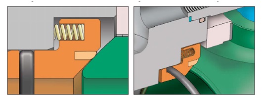
Soft Seat Ball Valve Design
Thermoplastic or Elastomeric seats are inserted in a metallic holder (seat ring) to provide soft seating action in a ball valve. The main features of a soft-seated ball valve are
Provide a good sealing ability.
Lower in cost than metal seated valves.
Limited temperature rating.
Should not be used in dirty services, particularly on floating ball valves.
Soft seat materials used are – PTFE, Nylon, Devlon, PEEK, etc.
It is generally accepted a leakage of ISO 5208 Rate A
Fig. 2 Soft Seat Design of Ball Valves
Metal Seat Ball Valve Design
The main features of metal-seated ball valves are
Direct metal-to-metal contact between seat ring & ball.
Ball Valves are used for abrasive service and for services where soft seated valves can not be used due to temperature limitations.
The ball & seat contact surfaces are hard-faced to improve resistance to wear & prevent scratching caused by the solid particles contained in the process media.
Metal sealing may be obtained by tungsten carbide coating (up to 200 deg. C), chromium carbide coating (above 200 deg. C), electroless nickel plating (ENP), or stellite hard facing.
Acceptable leakage of ISO 5208 Rate D.
Metal seats do not bed in as easily as soft seals under pressure. hence, ball and sealing rings to be precisely machined.
Metal-seated ball valves are posed to pitting, fretting, stress corrosion cracking, and intercrystalline corrosion damages.
3. Ball Valves Types: Reduced bore, Full bore, V-shaped, and Vented ball valves
Based on the inner diameter of the ball valve two types of ball valves are used in industries; Reduced Bore Ball Valve and Full Bore Ball valve.
Reduced Bore (Reduced Port) Ball Valve Design
Reduced port ball valves are quite common in the piping industry. However, reduced bore ball valves introduce frictional losses. The main design features of such ball valves are
The bore diameter is 1 size less than the pipe diameter for valve sizes up to 12” NB & 2 sizes less for 14” NB to 24” NB (and 3 sizes less for sizes above 24” NB).
These ball valves are comparatively smaller in size with less weight.
Fig. 3: Reduced Bore Ball Valve
Have lower operating torque, resulting in a lower cost actuated valve package.
Slightly higher pressure drop than full bore valve.
Prevents pigging
These valves are normally of a one-piece – end entry design for smaller sizes (up to 4”-150#) & two / three-piece – side entry design for bigger sizes.
These valves are also called regular port valves.
Full Bore (Full Port) Ball Valve Design
Full bore or Full port valves do not cause extra frictional losses, and the system is mechanically easier to clean as it allows pigging.
The bore inside diameter is the same as the pipe inside diameter.
Very little pressure drop.
Ball and housing are bigger.
Of higher weight than reduced bore valve, hence more costly.
Selected for specific process reasons, typically; minimum pressure drop, minimal erosion, pigging requirement, and gravity flow (to avoid liquid pocket)
V-shaped Ball Valves:
In V-shaped ball valves, The hole in the ball or the valve seat has a “V” shaped profile. This design offers more precise control of the flow rate.
Vented Ball Valves: In a vented ball valve design, a small hole is drilled into the upstream side to eliminate unwanted pressure within the valve.
4. Types of Ball Valves: One-piece, Two-piece, and Three-piece ball valves
Depending on the body construction of valves, there are three types of ball valve designs; One-piece, Two-piece, and three-piece ball valves
Single Piece Body Design Ball Valves
In the single-piece design ball valve, the body will be cast/forged as one piece. The insertion of the ball will be through the end of the body and is held in position by the body insert. This design offers the unique advantage of eliminating the possibility of external leakage to the atmosphere through bolted body joints. This design restricts the ball valve to be of reduced port floating design only (for sizes up to 4” NB).
Fig. 4: Single Piece Ball Valve Design
Two-piece / Three Piece Ball Valve Design
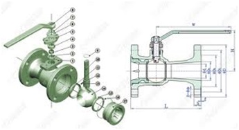
The two-piece design complements the single-piece design in sizes of 6” & above for reduced bore and for FB design valves. In a two-piece design, the body is constructed in two pieces and the ball is held in position by the body stud. There can be a full bore or reduced bore design possible in this construction.
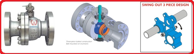
In the case of a three-piece design, the body has two end pieces and one centerpiece. Three-piece design ball valves are most easily online maintainable. By removing the body bolts and keeping only one, the body can be swung away using the last bolt as the fulcrum, to carry out any installation or maintenance operation on the valve. This feature reduces maintenance downtime to a bare minimum.
Fig. 5: Multi-piece Design
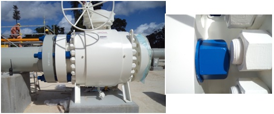
For larger 2-piece or 3-piece ball valves, the dimensions between the body and flange should be checked so that sufficient clearance is available for bolting. During the vendor drawing review stage, the same should be checked and ensured.
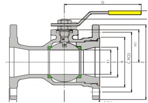
Fig. 6: Ball Valve Design
5. Ball Valve Types: Side entry, Top entry, or welded body ball valves
From the perspective of Ball Valve Body Styles, they are divided into three types of ball valve designs. They are
Side entry or end entry ball valves
Top entry ball valves and
Welded body ball valves
Side entry or end entry ball valve design
In the case of a side entry ball valve, the ball is assembled from the side part. They normally have two pieces or three pieces of the body. Each part of the body is assembled by a bolt/stud similar to joining a two-piece of flanges. Side entry ball valves are usually made by forging the metal. Each piece of the body is forged separately and then assembled together to get the complete design. This construction is robust in design and minimizes the defects caused by casting valves. Side entry ball valves are also easy to assemble and the trim component is also easy to align. Another advantage of the side entry ball valve type is that they are easily available from almost all vendors rather than a casting product that still needs some additional testing.
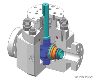
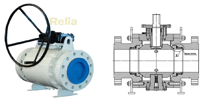
Top Entry Ball Valve Design
The main design features of top-entry ball valve types are
Maintenance and repair of such ball valves are possible in-situ, by removing the top flange. This minimizes maintenance downtime.
Limited space is required around the valve for maintenance.
Available in welded as well as flanged end connections, but welded ends are preferred to reduce potential leak paths and minimize the ball valve weight.
Heaviest and most expensive construction.
Fig. 7: Top Entry Ball Valve Design
Welded Body Ball Valve Design
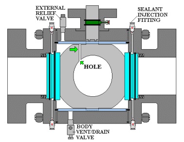
The main design features of this type of ball valve design are
Welded body ball valve construction eliminates body flanges, reduces potential leak paths, and increases resistance to pipeline stresses.
The minimum number of leak paths is hence beneficial in fugitive emission and vacuum applications.
Compact and lightweight design
The body draining & venting feature allows the ball valve maintenance technician to test each seat ring sealing ability with the ball in either the fully open or fully closed positions.
Sealant injection fittings access directly to each seat ring. This enables the technician to top up the quantity of lubricant inside the valve sealant injection system on a periodic basis.
Valve cleaner can also be injected into these fittings to flush out the old grease in the ball valve and to clean critical seal faces on the ball.
Heavier sealants are also injected through the sealant injection fittings during an emergency when a critical seal is required.
Applications – Oil & gas pipelines, compressor stations, measuring skids, etc.
6. Ball Valve Types depending on the type of ball design: Floating Ball Valve vs Trunnion Mounted Ball Valves
Depending on the supporting and positioning of the ball, two types of ball valves are used; Floating Ball Valves and Trunnion Mounted Ball Valves
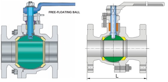
Floating or Seat Supported Ball Valve Design
In a floating ball valve, the ball is not fixed in place and is free to move slightly within the valve body. Sealing is achieved through the pressure of the fluid against the ball.
The major design features of a floating ball valve are
Ball valve design in which the ball is not rigidly held on its rotational axis & is free to float between the seat rings.
In the closed position, the ball is pushed against the seat by the pressure of the fluid from upstream and hence can pressure seal the downstream of the valve.
Ball seats on the downstream seat only.
Seat loading increases at a higher pressure and for larger sizes and becomes excessive, for the soft seated valve. Also, the higher the size the heavier the ball, and the less likely it is to be moved by pressure. Hence the need for a trunnion-mounted ball valve design comes into the picture.
Floating design ball valves have lower manufacturing costs.
Valves of small sizes and lower pressure ratings are seats supported (10” for 150#, 6” for 300# & 2” for 600# & above).
The seat-supported design generally needs higher operating torque.
Metal seated floating ball valves also incorporate spring-loaded seats.
Fig. 9: Floating Design of Ball Valve
Trunnion Mounted Ball Valve
Trunnion ball valves have a fixed ball with a shaft extending through it. This design provides more support to the ball, making it suitable for high-pressure and large-diameter applications. Trunnion ball valves are known for their increased durability and reliability in demanding conditions.
The major design characteristics of a trunnion-mounted ball valve are
The ball is fixed in position by the stem & the trunnion which are supported by bearings in the body.
The seat is spring-loaded onto the ball, giving reliable sealing at low pressures.
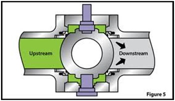
The key feature of this ball valve is that the ball does not shift as it does in a floating valve to press the ball into the downstream seat. Instead, the line pressure forces the upstream seat onto the ball to cause it to seal.
As the area on which the pressure acts is much lower, the amount of force exerted on the ball is much less, leading to lower friction values and smaller actuators or gearboxes.
Seat designs are either single or double-piston effects.
Valves of larger sizes and higher pressure ratings are trunnions mounted.
All standard trunnion-mounted ball valves shall be provided with self-relieving seats allowing automatic body cavity relief exceeding 1.33 times the valve pressure rating at 38°C (overpressure due to thermal expansion of trapped fluid).
Fig. 10: Trunnion Mounted Ball Valve
7. Types of Ball valves: Single vs. Double piston effect design
Based on the pressure relieving capability of the ball valve seats, two types of ball valves are designed; Single Piston Effect Design and Double Piston Effect Ball Valve Design
Single Piston Effect Seat Design
The important design features of single piston effect seat design are
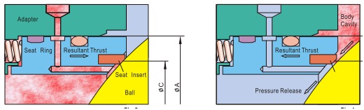
Seats of the ball valves are pressed on the ball by means of spring load.
As the body cavity pressure increases than the spring load, the seats are pushed back and the pressure is released in the line. This is called a single-piston effect (the pressure in the body cavity is the only acting parameter)
Cavity relief to the downstream side, if both the ball valve seats are of single-piston effect design.
Each seat is self-relieving the body cavity overpressure to the line.
Fig. 11: Single Piston Effect Seat Design
Double Piston Effect Seat Design
The design characteristics of a double piston effect seat design ball valves are
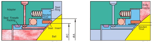
In this seat design, the medium pressure, as well as body cavity pressure, creates a resultant thrust that pushes the seat rings against the ball. This is called a double piston effect (the pressure in the pipe & that in the body cavity, both are acting parameters)
Ball Valves with this design require a cavity pressure relief device to reduce the body cavity pressure.
DPE is synonymous with “bi-directional”, and SPE is synonymous with “uni-directional” as defined by API 6D/ISO 14313.
Fig. 12: Double Piston Effect Seat Design
The working of Single Pistion Effect and Double Piston Effect Design is clearly shown in the following video:
Single Piston & Double Piston Concepts
Body Cavity Relief (Pressure Equalisation)
Ball valves are double-seated valves that incorporate a cavity between the seats.
The body cavity will get pressurized only when the seats are damaged.
Cavity relief provision is required only for trunnion-mounted ball valves. Not required for floating ball valves as the seats are fixed & the ball is floating.
Where possible, cavity relief shall be to the upstream side of the valve.
Fig. 12: Body Cavity Relief
DPE – External pressure relief
When the body cavity pressure increases above the net spring load of the pressure relief valve, the cavity pressure is vented through the Pressure Relief Valve.
The Relief Valve outlet line can be vented to the atmosphere / connected to the vent system or back to the upstream piping.
Fig. 13: DPE – External pressure relief
Combination Seats
In some cases, a single-piston effect seat is used for the upstream side and a double-piston effect seat is used for the downstream side.
This enables the cavity overpressure to release to the valve upstream side and also doesn’t require an external relief valve.
These ball valves are unidirectional and the flow direction is clearly marked on the valve body.
Ball valve Seat Design for Export Line
This seat configuration gives a single barrier against normal flow conditions and a double barrier against reverse flow coming from the downstream pipeline.
For the ESD/PSD valve, a reverse configuration is required than that shown here. ESD valves require SPE for the upstream seat and DPE for the downstream seat.