
In reality, the behavior of any system is not completely linear. Linear analysis can only approximate the behavior of the system to an extent. Generally, Non-linear behavior may be due to,
- Geometry,
- Material and
- Boundary conditions.
In Piping stress analysis,
- Geometry non-linearity is taken care of by means of Stress Intensification factors (SIF).
- Material nonlinearity is not considered, as the material is considered to be in the elastic limit.
- However, in Elasto-plastic analysis (For e.g. Blast), Material non-linearity shall be considered.
- Boundary condition non-linearity means having non-linear restraints (+Y), Supports with Gap and Friction.
However in Linear analysis (Linear Boundary condition)- Rigid restraints (two-directional) are to be used, No support gaps to be used and the effect of friction to be neglected.
The Static stress problems are solved by first assembling the equation,
[K]{X} = {F}
Where,
- K is the global stiffness matrix of the piping system,
- X is the unknown Nodal displacement vector,
- F is the known Nodal load vector (For each load case).
In Non-linear analysis, this Stiffness [K] changes during the iteration sequence when solving for
displacement in a particular load case. For e.g. When there is Rest support in a piping system, and if the pipe lifts off, then [K] is adjusted to remove the stiffness of that restraint. In Non-linear analysis, each Operating load Case (for particular support) could produce a different sustained stress distribution.
Whereas in Linear analysis, the model stiffness never changes since there are no Non-linear restraints,
those equations are assembled and solved just once for each load case, and stiffness is not updated
when the Piping system is deforming. Thus linear analysis follows a straight path. In stress analysis software packages the time taken by the software for convergence is lesser in linear analysis, whereas, in Non-linear analysis, the time taken is more because the stiffness is changed continuously.
Lift-up Support
If a Support lifts up in an operating cycle, it means it is inactive and the piping loads are distributed to
other supports in the vicinity, hence increasing the sustained stresses and with temperature, expansion
stresses change. When this operating cycle is maintained for a period, Sustained stresses remain the
same as there are no further lifts up of other supports in the system. Also, the expansion stresses will be
reduced due to yielding. During a shutdown, the pipe moves back to the support and hence the sustained stresses are reduced as the pipe comes (all supports become active) to its original cold condition.
If considerable yielding occurs in hot conditions, the pipe may return to the support point before the temperature reaches the ambient temperature. A continued cooling down to ambient temperature will cause very high thermal stresses and loads due to stoppage by the support which prevents the pipe from moving further down.
Generally, it’s good to avoid lift-up supports in a piping system as its inactive during operation. In linear analysis, we model Rigid supports. In some cases, lift-up supports may be required due to layout constraints.
In offshore projects, it is recommended to use support with Hold down in case of lift-up due to occasional load cases, if it’s not possible to avoid lift-up support. Hold-down supports with higher upward loads may cause overstress of the pipe. Providing Hold down still means the pipe is not seated on the structure in the operating case!
If the piping system has lift-up supports, it is mandatory to check all the stresses by removing the lift-up
support (Hot Sustain check). While calculating the Full displacement stress range, if liberal stress is activated, then we have to remove the lift-up support and calculate the full displacement stress range.
From ASME B31.3 302.3.5(d),
Allowable Displacement Stress Range, SA = f (1.25Sc+0.25Sh).
If we are activating Liberal Stress, it means we are using the difference between Sh and SL in the above
equation.
(Generally, SL will be lesser than Sh). Then, SA = f [1.25(Sc + Sh) – SL].
In the case of lift-up supports, this has to be taken care of. Removing the inactive supports during hot conditions may increase the sustained stress SL. Hence, the Liberal stress allowable would be lesser.
Here,
- Sc = basic allowable stress at minimum metal temperature expected during the displacement cycle under analysis= 138 MPa (20 ksi) maximum.
- Sh = basic allowable stress at maximum metal temperature expected during the displacement cycle under analysis= 138 MPa (20 ksi) maximum
- SL = stress due to sustained loads; in systems where supports may be active in some conditions and inactive in others, the maximum value of sustained stress, considering all support conditions, shall be used.
From CAESAR II 2016 edition onwards, the Hot sustain stress is been incorporated in load cases for
each temperature case. It calculates the Full Displacement stress range stress with liberal allowable
activated by removing the lift-up support.
The below table gives the details about Load cases considered in Linear and Non-Linear calculations.
Here, operating conditions are considered in Non-linear calculations.
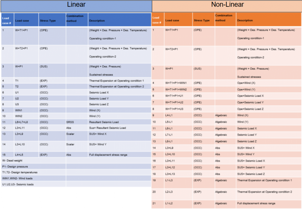
If some of the boundary conditions are non-linear (For e.g. If some lift-up supports) all load cases should
be evaluated considering an operating case.
Sustained case- (W+P1+T1)-T1 = W+P1
Occasional case- (W+P1+T1+WIN1)-(W+P1+T1) = WIN1 etc.,
If all the boundary conditions are linear in a piping system, the Sustained case is not impacted with respect to operating conditions.
Let us consider an example of a Pump Discharge system as shown in Fig. 2 below
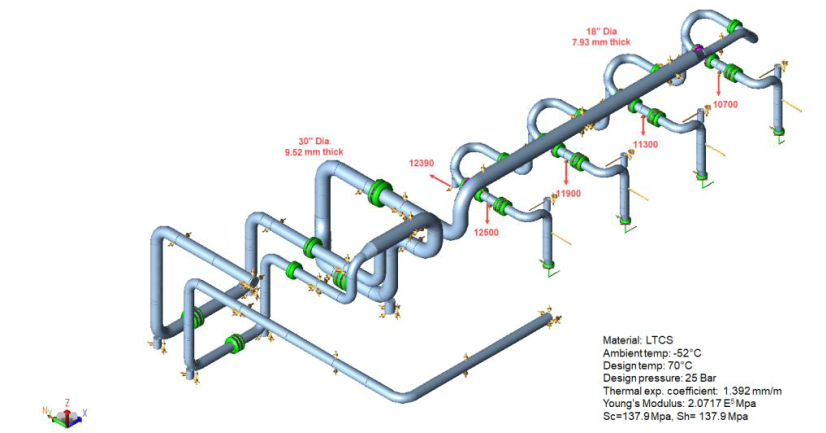
The above piping system is solved using Linear analysis with some lift-up supports at Nodes 10700, 11300, 11900, and 12500 let’s compare the results of the Sustained case (with and without considering operating conditions) with the same system by changing lift-up (Non-linear) into Rigid Z (Linear).
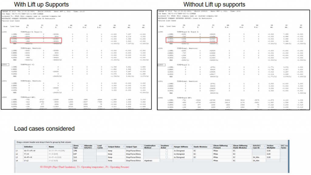
It can be inferred that with the lift-up supports, load changes are observed in the Sustained case with and without the operating case.
Support with Gaps
A restraint with a gap is also a form of nonlinearity. Hence operating effect is to be considered. Practically at the site condition, it’s not possible to maintain a zero mm gap in supports (The construction gap is a maximum of 2 mm.
Hence it may be without a gap or it may have a 2 mm gap. So, shall we use this advantage to solve the stresses and Nozzle loads in our Piping system? which may reduce additional flexibility (Elbows, more
compensation leg etc.,)
Pipe supports are used to take loads (Sustained, occasional, etc.) so that overloads induced by Piping
is not transferred to the equipment nozzle and to safeguard the Nozzle. So solving the equipment nozzle
using support with gaps near the nozzle may not guarantee that this support will take the load in all
operating scenarios.
For example,
Consider a line that has a design temperature of 120°C and an operating temperature of 50°C. In this case, the line will be mostly operating at 50°C and it may or may not fluctuate between 50°C to 120°C when the plant shutdowns, it will be at ambient condition. Hence, the support considered with the gap may not take loads at a certain operating condition which may result in overloading of the nozzle. Hence, it’s not good engineering practice to consider support with gaps near the nozzle to solve them.
It is good practice that the nozzle loads shall be checked without a gap and with a 2 mm gap up to a certain point. (i.e. maybe up to two rest, guide, stop varies on the situation). But whether support with gaps can be considered (as per the Stress engineer’s view) to solve high expansion stresses? if it’s not possible to change the routing, to give adequate flexibility, and reduce the additional piping components (Cost factor!) with a good engineering approach.
If we are using supports with gaps to have flexibility, then it is better to check loads, stresses and
displacements for both design and operating cases even if operating is far less than design.
Support Friction
As friction always opposes the motion, the effect of friction on a piping system can be advantageous in some scenarios, and may be non-conservative to ignore it in some scenarios. Please refer to the paper, “Treatment of Support friction in Pipe Stress Analysis” by LC Peng for a detailed explanation of Friction in the Piping system, which gives a detailed explanation of the behavior of support friction.
I think for occasional wind code stress, the combination method for linear shall be abs and non linear shall be scalar
Combination methods are wrongly shown for loads cases for Linear & Non-linear system. Apart from this, this is really a good presentation.
what is correct combination of load case ?