
START-PROF has Smart Operation Mode Editor instead of Load Case Editor.
When you add new load F or support movement D in CAESAR II , you must add it into load case editor manually, thinking thoroughly well what load cases should be created to properly consider it. If you will not add this load F or movement D into Load Case Editor, CAESAR II will not consider loads in the analysis.
In START-PROF you just add the load F or support movement D. Nothing more. It will be added automatically in that load cases where it should be added.
CAESAR II users who use the START-PROF for a first time always ask us the same question: “Where is the Load Case Editor in START-PROF?” or “How to create load cases in START-PROF?”. But START-PROF doesn’t have Load Case Editor. You don’t need to create load cases. At all.
The situation is similar to moving from Car Manual Transmission to the modern Car Automatic Transmission.
People who drive only cars with manual transmission ask a lot of unnecessary questions: How does automatic transmission works? How to shift the gear manually? How can I be sure that automatic transmission will shift the gear correctly?
Young drivers just sit in the car and enjoy driving without any questions about transmission, because it is working perfect.
It is hard to imagine how to work without Load Case Editor for people who used it for a many years. They ask a lot of questions: How do automatic load cases work? How to change the load cases manually? How can I be sure that automatic load cases work correctly, where to see it?
But young engineers just draw piping in START-PROF and enjoy the quick analysis results.
Load Case Editor is just technology from the past. Our idea is that engineers should think about piping design (driving a car), but not about load cases (how does automatic transmission works).
Example 1
You want to add additional occasional force “F” caused by Relief Valve Thrust https://whatispiping.com/modeling-relief-valve-pressure-safety-valve-thrust-force-in-start-prof or slug flow loads https://whatispiping.com/how-to-model-slug-flow-loads
You have to create the following load cases manually:
L1: W+P for sustained stresses (SUS)
L2: W+P+T for support loads (OPE)
L3: W+P+T+F for support loads with force F (OPE+OCC)
L4: L2-L1 (Algebraic) for expansion stresses (EXP)
L5: L3-L2 (Algebraic) Internal forces difference between operational mode with force F (L3) and operational mode without force F (L2). This way we get the pure internal forces from force F, but considering nonlinear behavior of structure (gaps, one-way restraints etc.)
L6: L1+L5 (Scalar) occasional stress is equal to the sum of stresses from sustained loads (L1) and stresses from pure internal forces (L5)
To understand how to create these load cases and what results should be analyzed from each load case, what is the difference between “Algebraic” and “Scalar” sum, engineer must spend a lot of time reading the literature, attend training courses, ask other people at forums etc. Only piping stress engineers with 5-10 year experience can create the correct load cases for each special situation without any errors.
Example of possible incorrect load cases:
L1: W+P (SUS)
L2: W+P+T (OPE)
L3: W+P+T+F (OPE+OCC)
L4: T (EXP) MISTAKE: nonlinear piping behavior will not be considered properly
L5: W+P+F (OCC) MISTAKE: nonlinear piping behavior will not be considered properly
There can be a lot of other human mistakes while creating load cases. The reason can be lack of knowledge or just misprint. Or you can just forget to consider some special features.
In START-PROF you can’t do a mistake with load cases. It’s like a car with automatic transmission, car developers already adjusted it to get the best results. You just create additional force-based loading (1.1) for the main operation mode (1). Number of submodes is almost unlimited. For example you can specify 100 submodes to model waterhammer loads using static method at different moments of time.
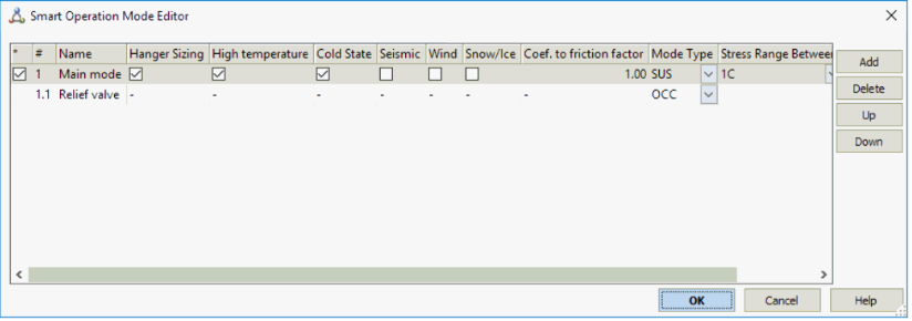
And add the thrust force.

START-PROF has a standard load cases inside. You can’t see it in software as you can’t see the mechanism of the car automatic transmission while driving.
For above example the force F will be applied in L11. See the table for ASME B31.3 code below. This table is just example. Each piping code has own template load cases inside START-PROF which accumulated our piping stress engineering experience for last 50 years to get best and accurate results.
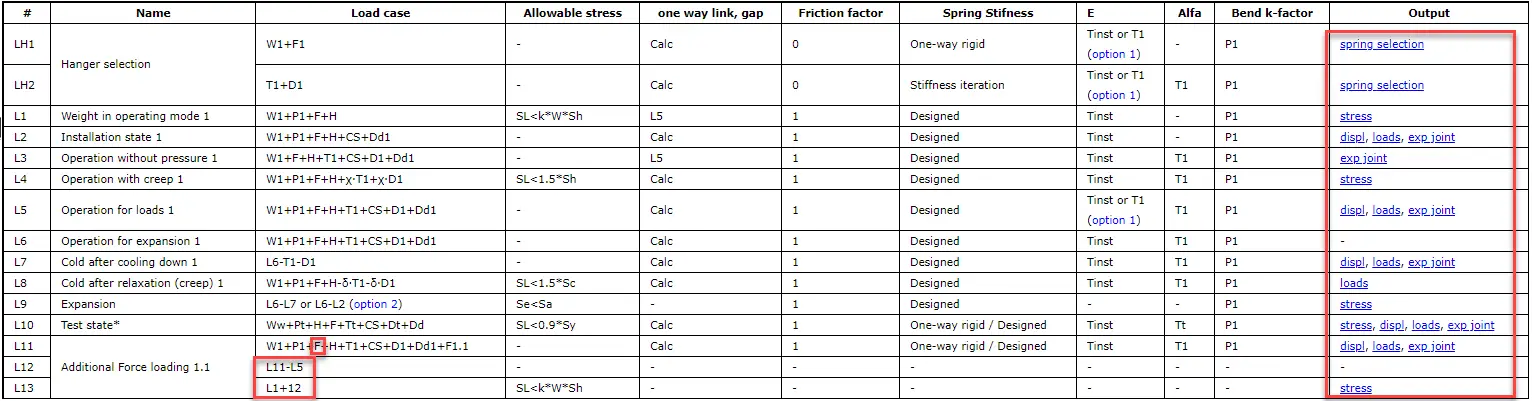
Load Cases L11 will be used to show displacements, loads, expansion joint deformations in the tables for user.
Load Cases L13 will be used to show occasional stresses
User can’t see the stresses from the L11 load case and can’t see the displacements from L13 load case. Because it doesn’t make sense.
Example 2
This diagram shows 39 loads cases from real project in CAESAR II, created manually. And shows operation modes in START-PROF that do the same job, but better, easier and faster (job analysis time in START-PROF is 2 times faster).
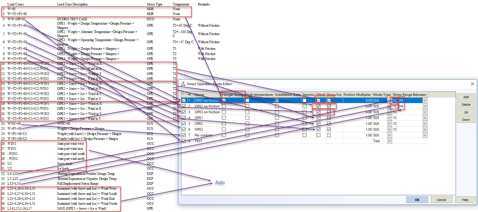
Operation modes are very easy to understand:
- #1: OPE1 – operation mode with temperature 65 deg. Friction is switched off. Occasional wind loads added (4 directions +X, -X, +Y, -Y). Two additional load cases added: snow and ice loads. Hangers are selected in this mode. Also installation (cold) state calculated for this mode
- #2: OPE2 – operation mode with temperature -100 deg.
Friction is switched off. Occasional wind loads added (4 directions +X, -X, +Y, -Y). Two additional load cases added: snow and ice loads. - #3: OPE3 – operation mode with temperature -47 deg.
Friction is switched off. Occasional wind loads added (4 directions +X, -X, +Y, -Y). Two additional load cases added: snow and ice loads. - #4: OPE1 – operation mode with temperature 65 deg. Friction is turned on. Occasional wind loads added (4 directions +X, -X, +Y, -Y). Two additional load cases added: snow and ice loads.
- #5: OPE2 – operation mode with temperature -100 deg.
Friction is turned on. Occasional wind loads added (4 directions +X, -X, +Y, -Y). Two additional load cases added: snow and ice loads. - #6: OPE3 – operation mode with temperature -47 deg.
Friction is turned on. Occasional wind loads added (4 directions +X, -X, +Y, -Y). Two additional load cases added: snow and ice loads. - #7: Operation mode with no fluid weight, operation temperature 0 deg. Friction is turned on.
- #8 Test mode. Test temperature and pressure used. Friction is turned on
- Stress range is calculated between 1H-1C, 1H-2H, 2H-1C, where 1 and 2 is operation mode number (#1 and #2), H – hot state, C – cold (installation) state