
Modal analysis is a powerful technique used in vibration engineering fields to understand the dynamic behavior of structures, mechanical systems, piping and pipeline systems, and other physical entities. It plays a crucial role in optimizing designs, improving product performance, and ensuring the safety and reliability of various engineering applications. In this comprehensive guide, we will delve deep into the world of modal analysis, to learn the following:
- Meaning of Modal Analysis
- Why is Modal Analysis Important?
- Criteria for Modal Analysis of Piping System
- Applications of Modal Analysis
- Modal Analysis Methods
- Piping Modal Analysis Software Programs
- Caesar II Piping Modal Analysis Procedure
- And Many more…
What is Modal Analysis?
Modal analysis is a technique used to study the dynamic characteristics of structures and systems. It provides valuable insights into how these entities respond to external forces or vibrations. Modal Analysis is the study (analysis) of the dynamic behavior (dynamic analysis) of the structural, piping, or pipeline system and is used to find the natural frequencies of vibration for the concerned structural system. Different modes of vibration (vibration characteristics) of the analyzed piping system are determined using Modal Analysis. The modal analysis helps to show the movement of different parts of the structure under dynamic loading conditions.
The primary goal of modal analysis is to determine the natural frequencies, mode shapes, and damping ratios of a system, which collectively describe its dynamic behavior.
Natural Frequencies:
These are the frequencies at which a structure or system tends to vibrate when subjected to an external force or disturbance. Natural frequencies are characteristic of the system’s mass, stiffness, and geometry.
Mode Shapes:
Mode shapes represent the spatial distribution of motion within a structure or system at a specific natural frequency. They describe how different parts of the system move in relation to each other during vibration.
Damping Ratios:
Damping ratios quantify the energy dissipation in a system, indicating how quickly vibrations decay after an external disturbance is removed.
Why is Modal Analysis Important?
Modal Analysis provides an overview of the limits of the response of a system. All elements of the piping systems like flanges, valves, pipes, etc. have an internal frequency at which they vibrate naturally. At this frequency, the components will allow an energy transfer from one form to another with minimal loss. When this frequency reaches the “resonant frequency,” the system amplitude increases to infinity, and high vibration is observed. Hence, modal analysis is used to find out all such frequencies so that the occurrence of resonance can be prevented. Modal analysis is also known as modal and frequency analysis.
Natural frequencies give us an idea of how fast the piping system is going to vibrate. The term natural means, that the system is in free motion without any external forces. So by performing modal analysis the following two points are discovered
- The natural frequency of the piping system and
- The corresponding modes of vibration
Criteria for Modal Analysis of Piping System
While performing stress analysis for piping/pipeline systems you might have come across the term two-phase flow. Most of the flowlines are believed to have two-phase flow. Several processes and oil & gas piping systems, too, carry the two-phase flow. Conventionally all two-phase flow (Slug Flow) lines are believed to be vibration-prone.
The stress analysis basis or flexibility specification of most of the relevant organizations informs the stress engineers to perform modal analysis for such systems and properly support these lines using hold-downs, guides, and axial stops to reduce the extent of vibration. It is a standard engineering practice to keep the natural frequency of vibration-prone lines in excess of 4 Hz. Now the question is how to calculate the natural frequency or modal frequencies of a complex piping system.
The modal analysis module of Caesar II dynamic analysis is also used to calculate the natural frequency of pipe systems connected to compressors and reciprocating pumps. Harmful vibrations will result when the pipe’s natural frequency is close to that of connected rotary equipment. In order to avoid resonance and subsequently fatigue failure, many organizations follow the below-mentioned two criteria while modal analysis
- f/fn>1.25 and
- f/fn<0.75
Here, f=excitation frequency of the rotating equipment and fn=piping natural frequency.
Applications of Modal Analysis
The modal analysis finds applications in various fields, including:
- Structural Engineering: In civil engineering, modal analysis helps assess the dynamic response of buildings and bridges to earthquakes, wind loads, and other environmental factors. It aids in designing structures that can withstand these forces and prevent catastrophic failures.
- Aerospace Engineering: Modal analysis is used to study the vibrations and dynamic characteristics of aircraft, spacecraft, and rocket components. This information is crucial for designing lightweight yet robust structures to enhance fuel efficiency and safety.
- Mechanical and Piping Engineering: In mechanical and piping systems, modal analysis assists in optimizing the design of components like engine parts, automotive suspensions, industrial machinery, and piping systems. It ensures that these components operate efficiently and do not fail under dynamic loading conditions.
- Automotive Industry: Modal analysis is used to evaluate vehicle chassis and suspension systems to improve ride comfort and handling. It also plays a role in reducing noise, vibration, and harshness (NVH) in automobiles.
- Electronics and MEMS: Modal analysis is applied to micro-electro-mechanical systems (MEMS) and electronic components to understand their dynamic behavior and improve reliability.
Methods of Modal Analysis
Modal analysis can be performed using various methods, including:
- Experimental Modal Analysis (EMA): This involves measuring the dynamic response of a physical system using sensors (e.g., accelerometers) and then extracting modal parameters through mathematical techniques like the Fast Fourier Transform (FFT) or system identification.
- Operational Modal Analysis (OMA): OMA is conducted on an in-service structure or system without artificially inducing vibrations. It relies on ambient vibrations or external excitations (e.g., traffic loads) to extract modal parameters.
- Numerical Modal Analysis: Numerical simulations, such as finite element analysis (FEA) or computational fluid dynamics (CFD), are used to predict the natural frequencies and mode shapes of a system based on its geometric and material properties. This method is often employed in the design phase.
Significance of Modal Analysis
The modal analysis offers several significant benefits:
- Design Optimization: By understanding a system’s dynamic behavior, engineers can make informed design choices to improve performance, reduce vibrations, and enhance durability.
- Failure Prediction: Modal analysis can identify potential failure modes and structural weaknesses, allowing for preemptive maintenance or design modifications.
- Quality Assurance: Manufacturers can use modal analysis to ensure that products meet performance specifications and standards, leading to higher-quality and more reliable products.
- Safety: In civil and aerospace engineering, modal analysis contributes to the safety and integrity of structures and vehicles by ensuring they can withstand dynamic loads and environmental conditions.
- Cost Savings: By avoiding overdesign and optimizing structures or systems, modal analysis can lead to cost savings in terms of materials and manufacturing.
Software for Piping Modal Analysis
Various software is available in the market to determine modal responses of structures by modal analysis. For piping and pipeline systems modal analysis is performed using the following software
- ANSYS
- Caesar II
- AutoPipe
- Start-Prof
- Rohr 2
- Caepipe
Out of the above, Caesar II by Hexagon is the most widely used software for modal analysis of Piping Systems.
Dynamic Modal Analysis Module of Caesar II
So, here comes the importance of a Caesar II dynamic module called the Modal analysis module. The complex job of calculating the natural frequency of the piping system becomes very easy with the use of this module. The vibration response or dynamic response of any system can be easily determined using modal analysis. In the actual case, Modal analysis breaks up a complex system into a number of modes of vibration, each of which has a unique vibration response. This article will elaborate on the steps followed for performing the modal analysis using Caesar II.
Modal Analysis Steps in Caesar II
To start the modal analysis you must have a stress system. So from the isometric model, the system follows conventional methods and perform the static analysis and make the system safe in all respect with respect to static analysis. Now follow the below-mentioned steps for dynamic Modal analysis:
Caesar II Modal Analysis Procedure
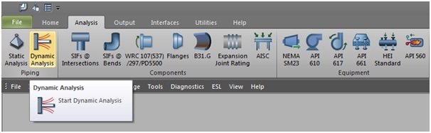
Click on Analysis-Dynamic Analysis as shown in Fig. 1 to open the dynamic module in Caesar II. It will open the window which is shown in Fig. 2.
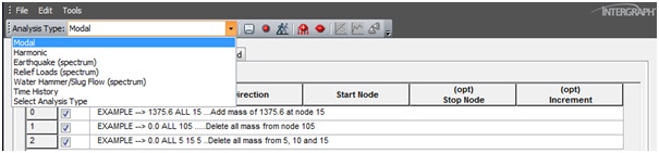
Now click on Analysis type and select Modal from the drop-down menu. You will get the following window as shown in Fig. 3.
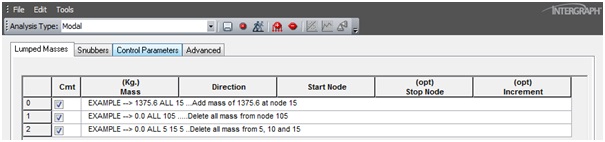
You will get four input spreadsheets as lumped masses, snubbers, control parameters, and advanced.
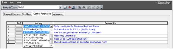
Click on Control parameters and it will open the window shown in Fig. 4.
Change the frequency cut-off to your desired frequency based on your project specification. If you need to arrest all frequencies below 5 Hz and set that value as 5. The stiffness factor for friction can be used up to a value of 100. However, few organizations prefer not to use friction forces in dynamic analysis so use the stiffness factor as zero.
Now select the static load case for which you want to extract the natural frequencies. Normally it is advisable to select the operating temperature case.
Run the Modal Analysis
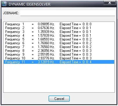
Now you are set for analysis, So click on the run button similar to what you do for static analysis. The analysis will extract all the natural frequencies in which the piping system will experience below your cut-off frequency values. Fig. 5 shows such a typical modal run screen.
How to interpret Modal Analysis Results
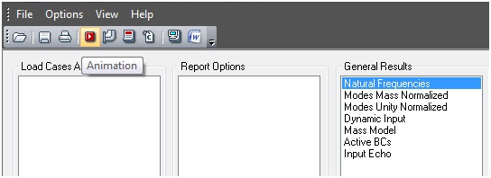
After the analysis run is complete the output screen will open. Select Natural frequencies to check the extracted natural frequencies of the system. Most of the time we check the animation view to get a feel of the actual vibration process. Select Natural frequencies and then click on the animation button as shown in Fig. 6.
In the animation, view and check how the system is experiencing vibration. Accordingly, provide support. Normally guide and line stop support with zero gaps will be required to arrest the vibration frequencies. Accordingly, provide support. Sometimes hold-down supports will be required. So, each time in the animation view find out the location where the system is vibrating and provide support near it. In most cases, the vibration occurs
- Near rigid bodies (valves, flanges, etc.)
- Long unsupported pipe spans
- Long pipe runs where guide support is not provided
- Straight lengths of pipe without line stops
So each time provide support at vibrating places in the piping system and re-run the modal analysis as mentioned above.
As soon as you provide a guide and line stop supports the system will become more rigid and expansion stresses will increase. So each time you change some support type you have to perform static analysis and make the system safe from all considerations and then proceed to the dynamic module.
Video tutorial on Modal Analysis Basics and related theories
The following video tutorial gives a nice explanation of the modal analysis basics and modal analysis theories.
Modal analysis is a vital tool in the field of engineering, enabling us to unlock the secrets of dynamic behavior in structures and systems. Whether it’s arresting the vibration of piping and pipeline systems, designing safer buildings, improving the performance of vehicles, or enhancing the reliability of electronic components, modal analysis plays a crucial role in shaping the modern world. With ongoing advancements in technology and analytical techniques, modal analysis continues to evolve, opening up new possibilities for innovation and engineering excellence.
Few more useful resources for you.
Slug Flow Analysis Using Dynamic Spectrum Method in Caesar II
It’s useful, Thanks for sharing, this website so great. So, can you continue with Harmony Analysis, Spectrum and History response. Thanks very very much.
sir , can you explain how much stiffness factor should we use in our system. As in modal analysis it is dynamic friction stiffness i.e. function of normal force. In that case how much stiffness should we use . As i feel its totally impractical to assume stifness 0 . Guide
If we use snubber to increase natural frequencies of system, how we should estimate snubber axial load to prepare its data sheet and apply for purchase?
Dear Mr. Anup,
I really appreciate your thoughts in sharing knowledge . Thankyou so much!
regards,
vivek
As a retired stress engineer I would help out?
Hi there…I have a question, if i have pipe span with this configuration: from left to right:
fixed—-supported————————————-supported—fixed,
← 0,6mt → ← 2 mt → ← 0.6 mt →
*———————–*———————————————————*————————–*
clamp support support clamp
I need to study the behavior of the 2 mts span: performing 1) modal analysis, 2)vertical pipe displacement.
SHould Itaaking into account the HOLE Structure ( 3.2 mts) , or just de (2mts) span
“How the stiffness factor for friction can be used up to a value of 100.”
Dynamic analyses in CAESAR II act only on linear systems, so any non-linearities must be linearized prior to analysis. Modeling of friction in dynamic models presents a special case, because friction impacts the dynamic response in two ways. Static friction (before breakaway) affects the stiffness of the system by providing additional restraint. Kinetic friction (after breakaway) affects the damping component of dynamic response. Due to mathematical constraints, damping is ignored for all analyses except time history and harmonics, for which it is only considered on a system-wide basis.
The software considers friction using this friction stiffness factor. The software approximates the restraining effect of friction on the pipe by including stiffnesses transverse to the direction of the restraint at which friction was specified. The stiffness of these frictional restraints is calculated as:
Kfriction = F * µ * Fact
Where:
Kfriction = Stiffness of frictional restraint inserted by the software.
F = The load at the restraint taken from the selected static solution. This load is the total resultant load acting on the restraint, including friction:
F = (Fx2+Fy2+Fz2)1/2
µ = Friction coefficient at restraint, as defined in the static model.
Fact = Friction stiffness factor. Units are fixed in 1/inch, so you must convert to other units. If stiffness Kfriction is defined in N/cm and force F is defined in N, then you must convert Fact to 1/cm:
Kfriction = F * µ * Fact * (1 in/2.54 cm).
You are kindly requested to explain the detailed mathematical calculations for the stiffness factor for friction