
Pipe spacing refers to the specific distance maintained between adjacent pipes in a piping system. Proper spacing ensures that pipes do not interfere with each other during thermal expansion, maintenance, or operational movements. It also helps in avoiding mechanical damage and provides sufficient room for inspection and repairs.
Why is Pipe Spacing Important?
- Maintenance and Accessibility: Adequate spacing allows for easier access to pipes for routine maintenance, repairs, and inspections.
- Thermal Expansion: Pipes expand and contract with temperature changes. Proper spacing accommodates these movements to prevent clashing and potential damage.
- Safety: Sufficient spacing helps avoid mechanical interference and reduces the risk of leaks or system failures.
- Optimized Layout: Efficient spacing can minimize the footprint of pipe racks, reducing construction costs and saving space.
Factors Influencing Pipe Spacing
Several factors must be considered when determining the appropriate spacing between pipes:
- Pipe Diameter, Flange Rating, and Size: Larger pipes and flanges require more space. The diameter of the pipes and the size of their flanges (if applicable) significantly influence the spacing.
- Insulation Thickness: If pipes are insulated, the thickness of the insulation must be considered when calculating spacing.
- Thermal Movement: Pipes experiencing significant thermal expansion or contraction require additional spacing to accommodate these movements.
- Pipe Racks and Supports: In pipe racks, spacing must account for the arrangement of flanges and the type of supports used.
What is a Pipe Spacing Chart?
A Pipe Spacing Chart provides the minimum distance between two adjacent pipes or pipelines. Whenever two pipes run parallel to each other, piping designers or engineers must maintain a minimum gap between the two pipes or pipelines.
Placing the pipes in proper order following a pipe spacing chart provides various benefits like:
- Proper pipeline spacing prevents the clash between pipes/pipelines during construction and erection.
- Sufficient Spacing accommodates sideways thermal movement of pipes generated due to thermal or occasional movements.
- Pipe spacing accommodates pipe supports, specifically guide plates.
So, to fulfill the above requirements and help pipeline and piping engineers during their pipe-laying activities, organizations prepare a standard pipe spacing chart. Following those standardized pipe spacing charts, the activities become quicker, and the chances of error during pipe and pipeline placement are reduced a lot. So, in a sentence, we can define a pipe spacing chart as a tabular representation of minimum pipe-to-pipe distances of various sizes.
Pipe spacing charts are very useful while routing pipes over a pipe rack or sleepers where lines of various sizes run parallel to each other.
Pipe Spacing Criteria
Various factors need to be taken one while piping or pipeline spacing. Some of those factors are:
- Adequate space for maintenance, inspection, and component repair must be provided during the layout.
- Spacing should be considered the worst free thermal movement between pipes. When the thermal movement is large, additional pipe spacing must be considered so that pipe thermal displacement is accommodated.
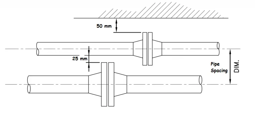
The usual practice to develop a pipe spacing chart is to consider a 25 mm gap between the outermost periphery of the piping components. So for example, if there are two pipes running parallel to each other, one having insulation and the other having a flange connection, a minimum of 25 mm gas has to be maintained in between the Insulation surface and flange surface. If both lines have a flanged connection, the flanges must be staggered to reduce pipe spacing between the two.
The formula for pipeline spacing:
The basic formula that is generally used to develop a pipe spacing chart is:
Centre to center distance between two adjacent pipes (mm)=half outer diameters of the bigger size pipe flange (OD/2)+half outside diameter of smaller size pipe (od/2)+ insulation thickness of both the smaller and bigger size pipe as applicable (T+t)+ 25 mm +Thermal displacement=(OD+id)/2 + (T+t) + 25 +Thermal displacement
The Pipe Flange Outer diameter is available in the flange standard. For example, ASME B16.5 is used for flanges up to 24″ in size and ASME B16.47 is used for flanges of size 24″ to 60″. AWWA C207 is used for flanges above 60 inches in size. For custom flanges or flanges designed with other standards, you have to refer to that standard.
Pipe outside diameter you will get in ASME B36.10/B36.19 standard.
Pipe insulation thicknesses, you will get in the project-specific insulation specifications. That will be a project-specific in-house document and can vary from project to project depending on the design criteria.
Thermal displacement needs to be calculated based on the worst situation consideration. For example, if two lines are running parallel to each other. One has a design temperature of 2500C (hotline) and the other has a design temperature of -460C (cold line). So, the hot line will expand and the cold line will compress. So, while calculating the pipe span both this displacement needs to be added. This means if the hot line expands by 30 mm and the cold line compresses by 15 mm then the thermal displacement that needs to be added in the pipe spacing calculation is 30+15=45 mm. However, if both lines are hot lines, then while thermal displacement calculation, consider a situation when one pipe is operating and the other is in ambient condition (preferably consider winter’s lowest ambient temperature).
So, using the above parameters in the above equation, you can easily calculate the pipe-to-pipe distance requirement for pipes of any size.
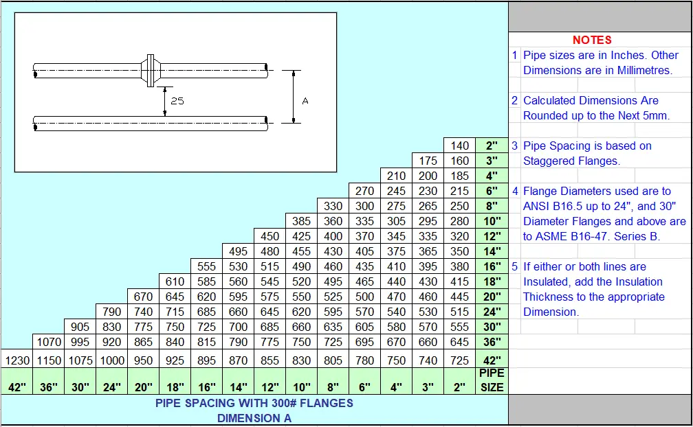
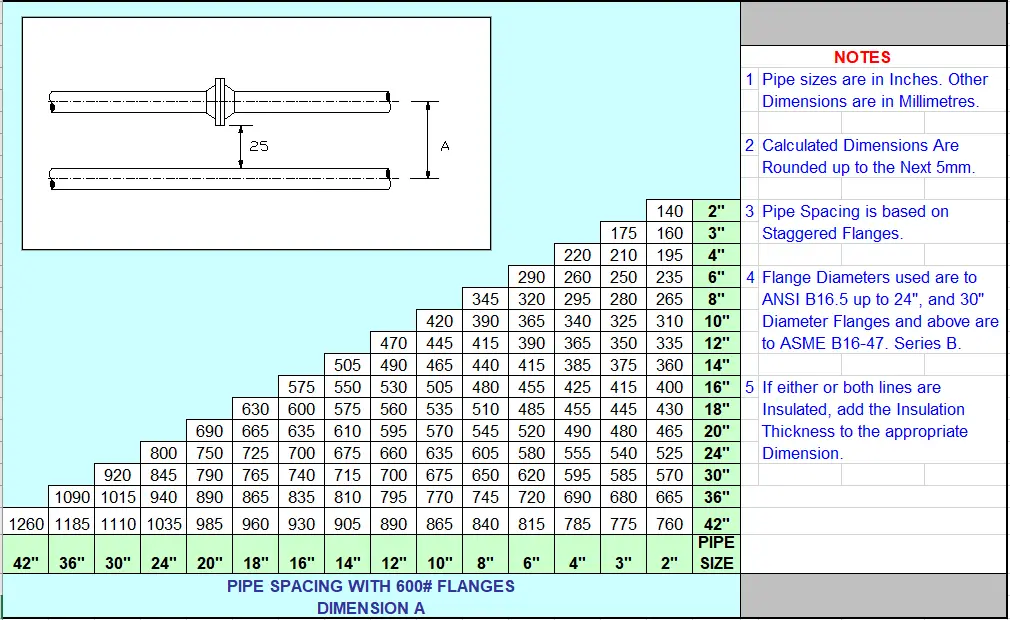
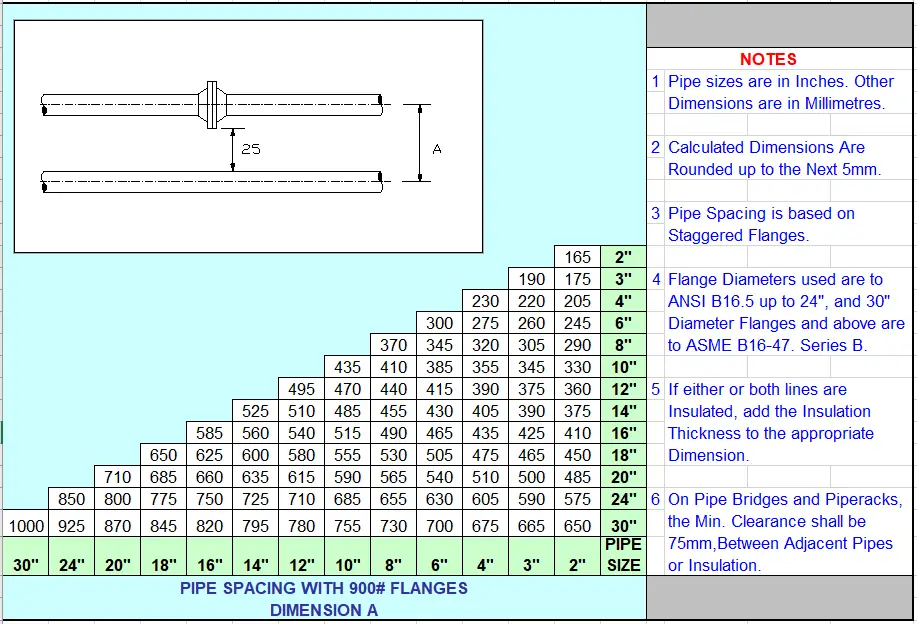
Pipe Spacing Chart
Standard pipe spacing charts are developed by organizations that provide center-to-center distance between two pipes. If there is a considerable amount of lateral thermal displacement (usually >15 mm) then the same needs to be added with the spacing values given in the standard pipe spacing charts. Typical pipe spacing charts are provided below to get an idea of the pipeline spacing charts used in the piping industry. However, these values may vary depending on the component design codes. So, it is always better to practice calculating using the above formula.
Pipe Spacing chart for pipes with 150 rating flanges

Pipe Spacing chart for pipes with 300-rating flanges
Pipe Spacing chart for pipes with 600 rating flanges
Pipe Spacing chart for pipes with 900 rating flanges
Using a Pipe Spacing Calculator
A pipe spacing calculator is a valuable tool for determining the correct spacing between pipes based on various criteria. Here’s how to use it:
- Select the Configuration: Choose from the four provided options, such as spacing between pipe centers, flange centers, or bare pipes.
- Input Dimensions: Enter the outer diameter (OD) of the pipes and flanges. For configurations involving flanged components, include the OD of the flanges.
- Calculate Spacing: The calculator will provide the minimum spacing required between pipes based on your input.
Spacing Between Pipes on a Pipe Rack
When pipes are arranged on a pipe rack, specific considerations are required:
- Staggered Flanges: If adjacent lines have flanged components, staggered arrangement is often necessary to optimize space and reduce the required footprint.
- Clamped Supports: If using clamped supports, larger spacing may be required. For cost-effectiveness, clamped pipe supports at a 45-degree angle are recommended.
Special Considerations
- Protruding Valves: For valves like full-bore ball valves with higher flange ratings, the valve body may extend beyond the flange OD. In such cases, specific calculations are needed to ensure adequate spacing.
- Non-Staggered Components: If flanged components cannot be staggered, ensure that the spacing accounts for the largest flange OD and any additional clearances.
thanks it is very usefull
Hi, I am Design Engineer for PHE systems. I would like to share my experience with you.
Please let me know about the space between 2″ inches CPVE pipe and PVC pipe. Thanks
Thank you for this valuable publication. As good and interesting as always👍
hello and thank you for sharing this information.
I wonder why we should consider 15mm for cold line while it getting smaller and as a result keep more disstance from the pipes around it.
is any standards for this pipe spacing?
Hai Sir
can u please tell me the formula refers to which standard….i mean we refer pipe for 36.10,flanges for 16.5,….but our applied formula where we get sir
hello I would like to know in which source or standard this information is stated.
Hello Sir,
kindly share me which ARAMCO standards use for pipe line CBT study