
What is Piping Thermal Bowing?
Piping Thermal Bowing or Bowing is an effect that occurs in horizontal piping run due to large circumferential temperature gradients which have the potential to cause large unacceptable local thermal stresses in the pipe walls leading to fatigue failure and high loads at pipe supports and connected equipment. The pipe may bend like a bow in such a situation and hence the name bowing effect. Because thermal bowing is very damaging, it is important to avoid the occurrence rather than to analyze the effect after the occurrence. This article will provide some guidance on how thermal bowing problems are considered in piping stress analysis using Caesar II software.
Which lines are prone to piping thermal bowing?
Pipe thermal bowing is a serious problem for
- partially filled cryogenic lines like LNG, LPG, etc or
- Uninsulated pipes which are exposed to the hot sun
- pipes carrying the stratified flow of low-temperature fluid in horizontal lines
- Steam lines in presence of external or internal water (Condensate)
- Stagnation of the flow which causes stratification
In such lines, the flow inside the pipe is such that one part of the pipe cross-section is hot and the other part is cold. For example in a partly filled LNG or LPG line, the upper part of the pipe cross-section will be in hot condition (so, the pipe will expand in the upper part) and the lower part will be in cold condition (so the pipe will contract in the lower part). A similar situation arises, where one side of the pipe is heated by the hot sun exposure and the other side is in the shade. So this simultaneous expansion and contraction or uneven temperature distribution will force the pipe to produce pipe curvature.
Piping thermal bowing problems are normally not addressed in pipe stress analysis or design books. But the share of operational difficulties due to thermal bowing is very high. Therefore, it should be properly treated in the design.
What is the thermal bowing temperature?
The diametrical temperature difference across the cross-section is called the bowing temperature. The bowing temperature occurs mostly in top and bottom directions and is mainly generated by stratified flow created by rapid quenching of high-temperature gas engaged in petrochemical production, emergency cooling injection, cold re-circulation, start-up of a liquefied natural gas transfer line, rapid deployment of cryogenic liquid fuel, and so forth. It can also be generated by the startup of a large steam pipe.
For considering piping thermal bowing in Caesar II this thermal bowing delta temperature is the additional input. Thermal Bowing Delta Temperature Specifies the diametrical temperature differential between the top and bottom of the pipe. This differential temperature is used to calculate an elemental load that is added to each temperature case. This temperature will be received from the Process engineering team.
Piping Thermal Bowing Assumptions for Stress Analysis in Caesar II
For stress analysis, it is assumed that
- the temperature distribution across the piping cross-section is linear and
- the same thermal gradient or temperature change is applied to the complete pipe and cannot specify different thermal bowing temperatures for different pipes.
Example Problem for Piping Thermal Bowing Stress Analysis in Caesar II
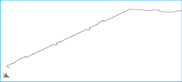
In this example, an 18-inch LPG line is considered (As shown in Fig. 1). The analysis parameters are as follows:
- Maximum Design Temperature: 82 Deg. C
- Minimum Design temperature: -46 Deg. C
- Operating Temperature: -42.4 Deg. C
- Thermal Bowing Delta Temperature: 50 Deg. C
- Design Pressure: 2900 Kpa
- Hydrotest Pressure: 4440 Kpa
- Pipe Material: A333-6
- Pipe OD: 457.2 mm
- Pipe Thickness: 11.91 mm
- Corrosion Allowance: 3 mm
- Fluid Density: 600 Kg/m3
- Cold Insulation Thickness: 80 mm
- Insulation density: 40 kg/m3
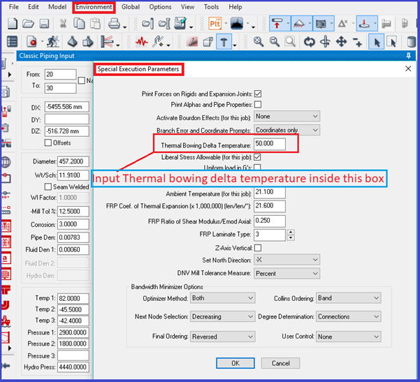
The pipe is to be modeled in the normal method which we do for other piping analyses. Additional input is thermal bowing delta temperature that has to be entered inside the special execution parameter as shown in the image (Fig. 2) below:
Next prepare all the required load cases for Analysis. Thermal bowing stress will automatically be considered for all thermal load cases. The following image (Fig. 3) shows the stress difference with thermal bowing and without thermal bowing effects.
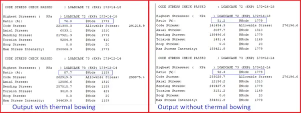
So it is clear from the above output results that there are changes in stresses. The same is true for support loads and thermal displacements.
Some more Resources for You…
Thermal Bowing Methodology Using Start-Prof
Stress Analysis using Start-Prof
Stress Analysis using Caesar II
Stress Analysis Basic Concepts
Piping Layout and Design
how can we calculate thermal bowing delta temperature?
The 50 deg c you inputted in Caesar II is based on what criteria could you please explain.
Sir can you explain about black body temperature calculation and how to apply in caesar ii
An example of Thermal Bowing can sometimes be seen on an Ethylene furnace outlet (Transfer) line when there is an uncontrolled build up of hydrocarbon deposits in the bottom portion of the line causing the top half of the line to expand more than the bottom. There were quite dramatic effects on the Grangemouth KG Furnace outlet line (many years ago). It is useful to have temperature monitoring around the circumference if carbon deposits are likely to occur in the line.