
A Steam Turbine is an engine that converts heat energy from pressurized steam into mechanical energy where the steam is expanded in the turbine in multiple stages to generate the required work. Steam turbine engines are used to produce electricity and drive countless machines worldwide (used as the prime mover for pumps, compressors, and other shaft-driven equipment). The capacity of steam turbines can vary from a few kilowatts to several hundred megawatts. Sir Charles A. Parsons developed the first modern steam turbine in 1884.
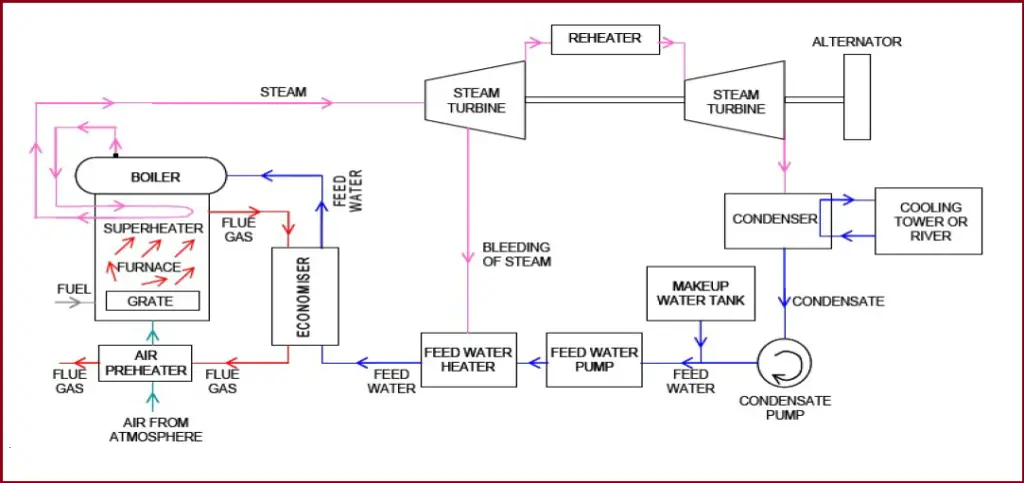
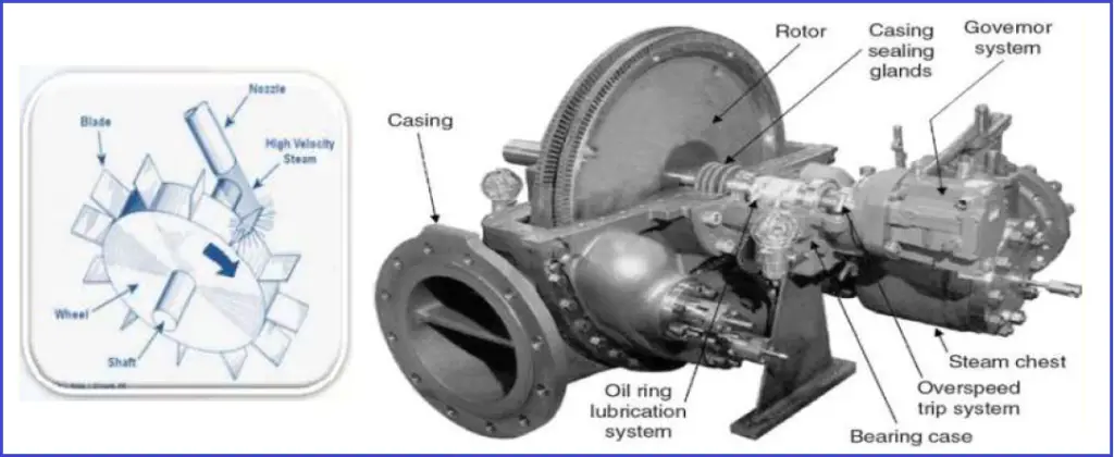
The Power in a steam turbine is generated by the rate of change of momentum of a high-velocity jet of steam impinging on a curved blade that is free to rotate. Fig. 1 below shows a schematic representation of a steam turbine with its associated auxiliaries.
Working Principle of Steam Turbines
The heat energy of steam is converted into mechanical work while expanding in the turbine. Steam is generated inside a boiler. The expansion of steam takes place through a series of fixed blades (nozzles) and moving blades. The working of a steam turbine is based on the thermodynamic cycle called the “Rankine cycle”.
Rankine Cycle:
The Rankine cycle is an idealized thermodynamic cycle of a heat engine that converts heat into mechanical work while undergoing a phase change. The concept is developed by William John Macquorn Rankine, a Scottish polymath and Glasgow University professor. It is an idealized cycle in which friction losses in each of the four components are neglected. The heat from an external source is supplied to a closed-loop, which normally uses water as the working fluid. Refer to Fig. 2
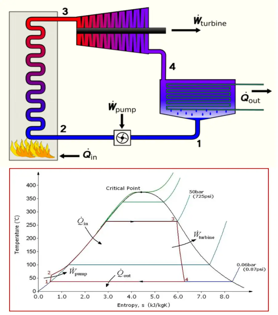
Fig. 2 above represents the Rankine Cycle and the Temperature and Entropy are plotted in the curve. The processes can be described as follows:
- Process 1–2 Isentropic compression – Adiabatic Pumping: The working fluid is pumped from low to high pressure. The fluid, being liquid at this stage, the pump requires little input energy.
- Process 2–3 Constant pressure heat addition in a boiler – Isobaric Heat Supply: The high-pressure liquid enters a boiler, where it is heated at constant pressure by an external heat source to become a dry saturated vapor (steam). The required energy input can easily be calculated graphically, using an enthalpy–entropy chart (Mollier diagram or h-s chart), or numerically, using steam tables.
- Process 3–4 Isentropic expansion – Adiabatic Expansion: The dry saturated vapor expands through a turbine, generating power. The temperature and pressure of the vapor are reduced causing some condensation.
- Process 4–1 Constant pressure heat rejection in condenser – Isobaric Heat Rejection: The wet vapor then enters a condenser, where it is condensed at a constant pressure to become a saturated liquid.
Types of Steam Turbines
Steam Turbine Types can be classified based on various parameters as listed below:
- According to the action of steam
- Impulse Turbine and
- Reaction Turbine
- According to the number of pressure stages or impellers
- Single-stage Turbine and
- Multistage Turbine
- According to the type of blade row
- Rateau type(Pressure compounded stages)
- Curtis type (Velocity compounded stage)
- Reaction stage type
- According to the type of steam flow
- Axial flow turbine and
- Radial flow turbine
- According to the number of shafts
- Single-Shaft
- Multi-shaft.
- According to the direction of Shaft
- Transverse type
- Vertical type
- According to the method of governing
- Throttling
- Nozzles
- Bypass governing.
- According to the heat drop process:
- generators
- one or more intermediate-stage extraction
- back pressure
- topping.
- According to steam conditions
- Low-Pressure Steam Turbine
- Medium Pressure Steam Turbine
- High-Pressure Steam Turbine
- Very High-Pressure Steam Turbine
- Supercritical Pressure Steam turbine
- According to Exhaust conditions
- Condensing Turbine
- Backpressure Turbine
- Extraction Turbine
- According to the Exhaust flow
- Single-flow exhaust type
- Multi-flow Exhaust type
- According to Exhaust Direction
- Down exhaust
- Top exhaust
- Axial exhaust
- According to speed
- Fixed speed
- Variable speed
- Low Speed (≤ 3000 rpm)
- High Speed(≥ 3000 rpm)
- According to the quantity of the inlet valves
- Single valve type
- Multi-valve type
- According to the existence of reducer
- Direct-drive type
- Reduction type
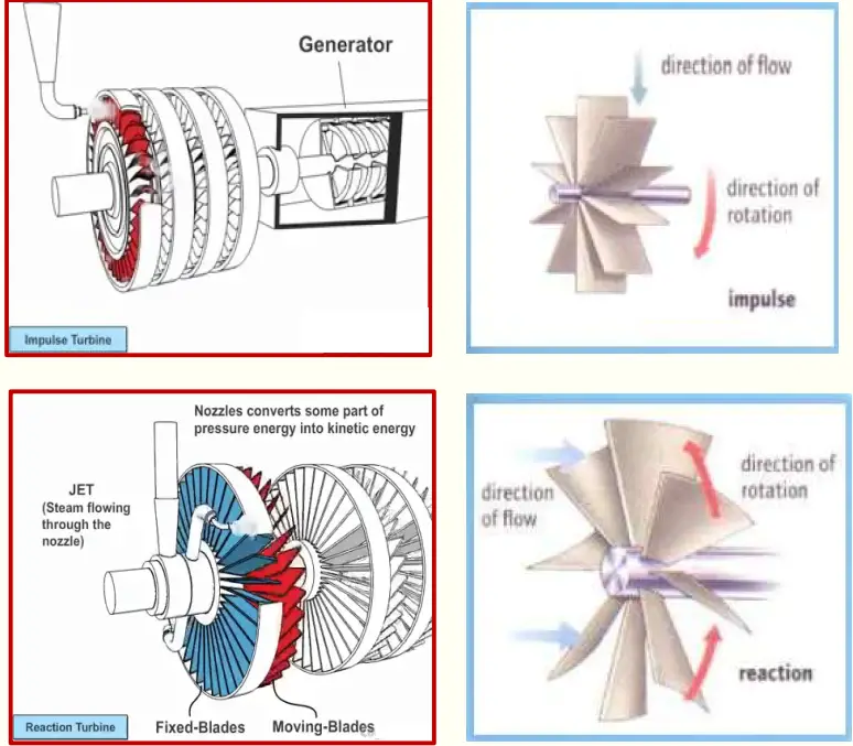
The most basic steam turbine types are Impulse Turbine and Reaction turbine.
Impulse Steam Turbine
The basic idea of an impulse steam turbine is that a jet of steam from a fixed nozzle pushes against the rotor blades and impels them forward. So the impulse force of high-velocity steam exerts a force on the blade to turn the rotor. The kinetic energy of the steam is transferred to the rotating wheel by momentum transfer within the blades. Pelton Wheel, Banki Turbine, etc are typical examples of Impulse turbines.
Reaction Steam Turbine
In the reaction steam turbine, a jet of steam flows from a nozzle on the rotor (the moving blades) by fixed blades designed to expand the steam. The rotor gets its rotational force from the steam as it leaves the blades. Roughly 50% of the output power is generated by the impact force and the other 50% from the reaction force by the steam expansion. Francis Turbine, Kaplan Propeller turbine, Deriaz turbine, etc are examples of reaction turbines.
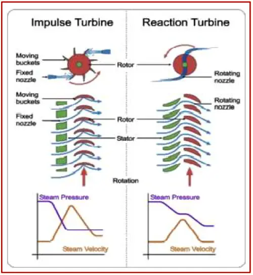
The main difference between impulse and reaction turbines lies in the way in which steam is expanded while it moves through them such that:
- In the impulse-type steam turbine, the steam expands in the nozzle and its pressure doesn’t change as it moves over the blades.
- In the reaction type, the steam expands continuously as it passes over the blades and thus there is a gradual fall in pressure during expansion.
The major differences between an impulse turbine and a reaction turbine are tabulated below:
| Impulse Steam Turbine | Reaction Steam Turbine |
| In an impulse turbine, The steam flows through the nozzle first and then strikes the moving blade. | In a reaction turbine, Steam flows through the guide mechanism first and then through the moving blades. |
| Blades rotate only by impact force | Blades rotate by impact force and reaction force generated by steam expansion. |
| Relative fluid velocity remains constant across the blades | The relative fluid velocity increases across the blade. |
| The number of stages is less for impulse steam turbines for the same heat input. | Reaction steam turbine has more stages under the same heat supply. |
| More efficiency | Comparatively less efficient |
| Less Maintenance requirement | More Maintenance requirements. |
| The casing does not perform any hydraulic function but is required to prevent fluid splashing. | The casing is a must to contain the pressure. |
| Fluid Flow is tangential to the turbine wheel | Fluid flow is radial or axial to the turbine wheel. |
| Suitable for small power generation. | Ideal for higher power generation requirements. |
| High operating speed | Low Operating Speed. |
Selection of Steam Turbines
The following table from JIS B0127 provides typical guidelines for the general features and selection criteria based on the type of steam turbines. Depending on the purpose, use, required output, location, arrangement, and circumstances appropriate type of steam turbine should be selected:
| Type of Steam Turbine | General Features | Selection Criteria | Use for |
| Condensing Steam Turbine | The turbines which work fully inflated to low pressure by obtaining a high vacuum in order to condense turbine exhaust steam in the condenser. | (1)When only electricity or power is required, (2) When cooling water to condensate exhaust steam is available. | Machine drive, geothermal power, heat recovery |
| Regenerative Steam Turbine | The condensing turbine which is obtained high efficiency of the turbine cycle by utilizing extracted steam from the middle stage for heating boiler feed-water by the feed-water heater. | (1)When small and middle output and high efficiency are required, (2) When cooling water to condensate exhaust steam is available. | Power generation for cement, ironworks, mine |
| Reheat Steam turbine | The turbines extract steam from the middle expansion stage, re-heat, back to the turbine and expand further. | (1)When large output and high efficiency are required, (2)In general, it is used as a regenerate and reheat turbine. | Large-scale power generation |
| Back-pressure Steam Turbine | The turbine’s exhaust pressure is above atmospheric pressure and utilizes steam as utility steam. In some cases, it may be operated exhaust released into the atmosphere. | (1)When a large amount of utility steam of a type is required, (2)It is necessary to operate electricity and steam in parallel due to excess and deficiency between generated electricity and the power demand of the plant. | Private power generation, machine drive, cogeneration |
| Extraction Condensing Steam Turbine | The turbines extract steam from the middle stage of condensing turbine after adjusting pressure by the control valve and utilize steam and exhaust steam as utility steam for works and others. | (1)When a large amount of utility steam of one or more types is required, (2)When the power demand is less than the amount of utility steam. | Private power generation, machine drive, cogeneration |
| Extraction back pressure Steam turbine | The turbines extract steam from the middle stage of the back pressure turbine after adjusting pressure by the control valve and utilize steam and exhaust steam as utility steam for works and others. | (1)When a large amount of utility steam of more than two types is required, (2)It is necessary to operate electricity and steam in parallel due to excess and deficiency between generated electricity and the power demand of the plant. | Private power generation, machine drive |
| Mixed-pressure Steam Turbine | The turbines which are made work into same turbine different pressure steam. | (1)When only electricity or driving power is required. (2)When it is necessary to collect low-pressure steam. (3)When it is capable to get cooling water for condensation of exhaust steam. | Private power generation by heat recovery, machine drive |
Components of a Steam Turbine
The major components that constitute a steam turbine are:
- Casing: The Casing should withstand all normal and emergency service loads and allowable piping forces and moments caused by temperature change. The design of turbine casing design shall be such that thermal stresses are minimized. Adequate support must be provided to the steam turbine casing to maintain good alignment with the rotor.
- Nozzles.
- Rotor: This is the main component in a steam turbine that carries the blades to convert thermal energy.
- Blades: Blades absorb the energy of high steam velocity and convey it to the rotor. The shape of the blades significantly affects the turbine performance of turbine and requires high reliability.
- Governor for speed control.
- Servo Mechanism.
- Oil Pump for lubrication.
Fig. 5 shows these components.
Construction of a Steam Turbine
Often, Turbines are described by the number of stages that are grouped into different sections of the turbine. Depending on the pressure levels, the sections are known as the high pressure (HP) section, intermediate pressure (IP) section, or low pressure (LP) section. These turbine sections can be constructed in different types as mentioned below:
- can be packaged into separate sections in a single turbine casing,
- can be arranged into separate casings for each section, or
- can be constructed in combination (HP/IP turbines in one casing and LP turbines in another).
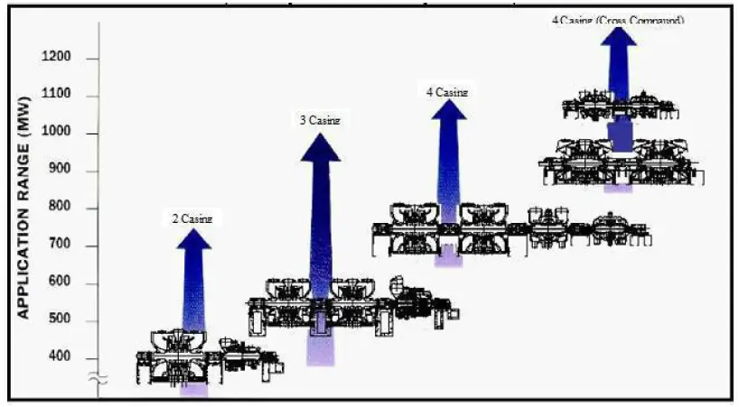
Also, two turbines may be connected together in the same casing but in opposing directions to balance the thrust loads. Flow to these turbines is through the center of the casing and exits from each end of the turbine. These are referred to as turbines with double flows (i.e., opposing flow paths on the same shaft). However, the steam turbine MW rating is not indicative of section or casing numbers. Normally, less number of stages and casing will result in larger size blading and high loading for the same steam condition. The following Fig. shows a typical plot of the number of turbine casings as a function of steam turbine size
Losses in a Steam Turbine
- Residual velocity loss.
- Losses in regulating valves.
- Loss due to steam friction in the nozzle.
- Loss due to leakage.
- Loss due to mechanical friction.
- Loss due to wetness of steam.
- Radiation loss.
Popular Problems of a Steam Turbine
- Fatigue, Thermal / Corrosion (Pitting / Stress Corrosion Cracking – Steam quality & excessive process conditions).
- Vibration (loose parts / excessive process conditions – Overload).
- Misalignment (Vibration / poor maintenance workmanship).
Steam Turbine Protection Means
- Over speed trip.
- Master Trip.
- LP Trip.
- Low Lubricating Oil Pressure Trip.
- High Bearing Temp. Trip.
- High Vibration Trip.
- High Axial Displacement Trip.
- Relief Valve in Exhaust
Techniques to Improve Steam Turbine Efficiency
Various techniques are employed to maximize steam turbine efficiency, each designed to attack a specific loss mechanism. For example:
- the number of stages utilized can range from the fewest possible to develop the load reliably to the thermodynamically optimum selection.
- Spill bands can be utilized to minimize throttling losses.
- High-efficiency nozzle/bucket profiles are available to reduce friction losses.
- To reduce the pressure within the exhaust casing, exhaust flow guides are available.
- The specific features employed on a given application are usually based on the trade-off between capital investment and the cost to produce steam over the life of the turbine –SIMPLY, IT IS AN OPTIMIZATION APPROACH.
Process Surveillance – Why we should monitor closely?
Accurate measurement and tracking of parameters like temperature, pressure, and flow are important to plant safety and performance. Information collected at specific measuring points can be used to:
- Avoid Metallurgical Failures: Temperatures need to be maintained below components’ melting points in order to avoid metallurgical failure. Too-high temperatures can also lead to creep deformation in the rotating blades.
- Determine Efficiency and Performance: Calculate the efficiency of the turbine by knowing the inlet and exit temperatures, as well as the flow rate at the nozzle. When a turbine exhaust is used as heat input to a steam cycle, engineers can also estimate the performance of the heat recovery steam generator (HRSG) by using the temperature and flow measurement of the turbine exhaust.
- Detect Inefficiencies: High exhaust temperatures and flow changes can be symptoms of an upset mode of turbine operation. If a flow measurement device picks up irregularities, the plant operator can perform a diagnostic to identify the underlying causes.
- Calculate Residual Life: Tracking temperatures over time allows one To calculate how much life the component has left and to plan maintenance and replacements.
Process Surveillance – What & Where?
- Barometric pressure.
- Steam and steam condensate’s flow rate, temperature, and pressure on:
- The cold reheat.
- The high-pressure throttle.
- The hot reheat.
- Low-pressure induction sections.
- Exhaust pressure.
Steam Turbine Codes and Standards
API 611 (ISO 10436) 4th Edition – General purpose steam turbines for refinery service (non-critical):
- General purpose turbines are horizontal or vertical turbines used to drive equipment that is usually spared, is relatively small in size (power), or is in non-critical service.
- They are used where steam conditions will not exceed a pressure of 48 bar and a temperature of 400°C or where speed will not exceed 6000 rpm.
API 612 (ISO 10437) 6th Edition – Special purpose steam turbine for refinery service (critical):
- The purchaser’s approval is required for built-up rotors when blade tip velocities exceed 250 m/s at maximum continuous speed or when stage inlet steam temperatures exceed 440 °C.
- Over Speed shutdown system:
- I. Electronic Overspeed detection system.
- II. Electro-hydraulic solenoid valves.
- III. Emergency trip valve(s) / combined trip and throttle valve(s).
- If specified a turbine with an exhaust pressure less than atmospheric pressure shall be provided with an exhaust vacuum breaker actuated by the shutdown system.
- Details of such a system shall be agreed upon by the purchaser and the turbine vendor.
Other codes and standards that are referred to for steam turbine applications are
- ASME/NEMA SM23
- NEMA SM24
- IEC 60045
- IEEE 122
- IEC 60953
- IEC 60962
- IEC/TS 61370
- BS EN60045-1
- ASME PTC 6/6A
- ASME/ANSI PTC 20.1/20.2
- ISO 14661
- IS 14205
- JESC T0003
- JEAC 3703
- JIS B8101
- DIN 4304
- DIN 4305
- DIN 4312
- DIN EN 45510-5-1
Steam Turbine Manufacturer
Steam turbines are highly complex and sensitive pieces of machinery, and only a few manufacturers produce them worldwide. The majority of the steam turbines are manufactured by the following companies:
- Harbin Electric
- Shanghai Electric
- Dongfang Electric
- General Electric
- Siemens
- Alstom
- Bharat Heavy Electricals Limited
- Doosan
- Mitsubishi Heavy Industries
- Weir Allen
- Elliot Group
- and Toshiba.
Online Steam Turbine Courses
To update yourself regarding more details of steam turbines, the following online courses will help you. To enroll in any course, click on the subject, review the course and then enroll.
Dear sir
Really this subject is informative for me.Please send this soft copy pdf to my mail.
Thanks
Sazzad Hossain
Turbine Shift Engineer
HF Power Ltd.
Bangladesh
Can you please elaborate on how turbine exhaust conditions can be used to assess the performance of HRSG? If possible please provide methodology as well.
Really need some more information about steam turbine about the risk of it and some advice about starting up a turbine while it’s loaded with machinery
very helpfull for me, thank a lot
Great performance