A Separator is a type of pressure vessel that is used to separate the gas and liquid from a two-phase mixture. The two-phase separator separates the liquid and gas phases from the mixture.
Pressure vessels are widely used in the process plant industry. Pressure vessels serve various functions such as
- short-term hold-up, i.e. day tanks, surge vessels,
- pressurized storage storages, i.e. bullets, Horton spheres,
- 2-phase (V/L) / 3-phase (V/L/L) separators,
- Special purpose vessels such as reactors, columns, and jacketed vessels.
The most common shape of pressure vessels is a cylindrical shell with dished ends. Other types of end closures such as conical, and hemispherical are also used when appropriate. For large pressurized storage, a spherical shape may be chosen. The Standard Engineering codes used for the design of 2-phase separators are GPSA guidelines, and API 12J.
Orientation of Separators
Pressure vessels/Separators can be installed in vertical or horizontal orientation.
Vertical Pressure Vessels
Vertical orientation is preferred to horizontal orientation owing to the following advantages:
- Lower plot space required: In most cases length (or height) of pressure vessels is more than the diameter. Therefore, the layout space required is lower when a vessel is placed vertically.
- Pumps are commonly used for the transfer of liquids from pressure vessels. The vertical vessel provides a higher NPSH available for the pump, as the operating level is at a higher elevation. This is advantageous for the design of the pumps.
- The vertical installation provides better utilization of vessel volume as the working volume between the high and low operating levels. This is illustrated in Fig. 1 below:
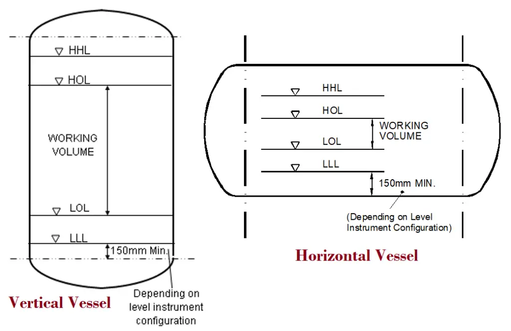
Horizontal Pressure Vessels
A vessel may be oriented horizontally when higher mechanical strength is needed to support the weight. This is especially important in the case of high-pressure vessels and very long vessels (high L/D ratio). Horizontal vessels can be provided with two or more saddles.
Two-Phase (V/L) Separator Design
Depending on fluid phases the separators can be classified into two groups.
- Two-Phase Separator and
- Three-Phase separator
Two-phase separators handle two-phase fluids. One is the gaseous phase and the other is the liquid phase. While a three-phase separator can separate out three phases; normally a gas, oil, and water (two liquid phases and one gas phase). In the following paragraphs, we will briefly explore the design basics of two-phase separators.
Selection of Separator: Horizontal or Vertical
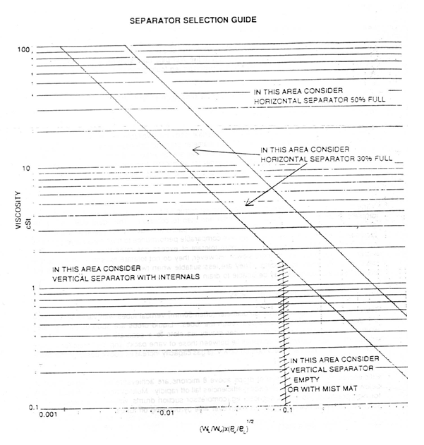
As a rule, a vertical drum should be chosen when the ratio of vapor to liquid volume is large (750 or more). The vertical drum is often preferred since the separation efficiency does not vary with the liquid level in the drum. Also, the plot space required is lower for the vertical drum.
The figure given below (Fig. 2) is used as guidance for the selection of the orientation of separators.
Choice of Separator Internals
Separator Internals are provided to increase the efficiency of the separator and reduce entrainment. The Internals available commercially is Demister Pads, Vane packs, Multi cyclones, or swirl decks. The size of droplets present in the two-phase flow entering the drum decides the type of internals to be used. Droplet size depends on the flow regime of the inlet pipe. The diameter of the inlet pipe should be selected to avoid dispersed, annular, or mist flow. The approximate size of droplets present in the vapor phase is given by:

| Symbol | Description | Units |
| d | Drop diameter | m |
| D | pipeline internal diameter | m |
| g | acceleration due to gravity | m/s2 |
| k | Souder’s Brown proportionality constant | k/s |
| ρ | density | kg/m3 |
| σ | surface tension | N/m |
| v | velocity | m/s |
| W | mass flowrate | kg/s |
| P | pressure | bar |
| ν | kinematic viscosity | m2/s |
| μ | dynamic viscosity | Ns/m2 |
| Subscripts | ||
| v | gas/vapor phase | |
| l | liquid phase |
Determining Separator Diameter
The design methods are based on Souder’s-Brown equation
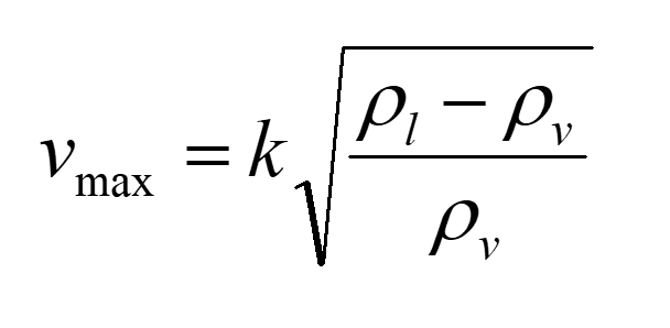
The maximum allowable velocity of the vapor phase is given by the value of vmax calculated by the Souder’s-Brown equation. The diameter of a vertical separator is calculated based on the value of vmax.
In the case of a horizontal vessel, the full cross-section area for the flow of vapor is calculated based on the value of vmax. This is in turn used to calculate vessel diameter.
Typical Values of Proportionality Constant, k
Different values of the proportionality constant k are applied for the internals and orientation of the separator.
| k value, m/s | |
| Vertical knock-out drums | |
| Empty knock-out drum | 0.08 |
| Empty Compressor suction drums | 0.04 |
| Flare knock-out drum | 0.07 |
| Horizontal knock-out drums | |
| Empty, for bulk separation | 0.1 |
| Empty Compressor suction drums | 0.05 |
| Vertical demister mat KO drum | 0.105 |
| Horizontal demister mat KO drum | 0.15 |
Deciding the Height of the Separator
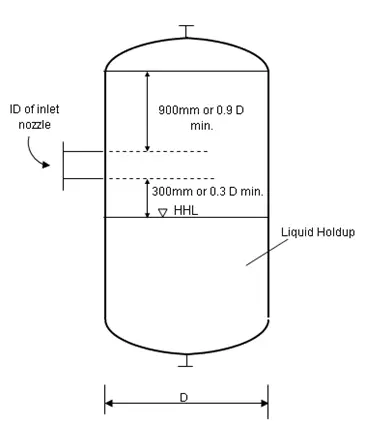
The height of the separator or drum is calculated considering the following requirements:
- Between the high liquid level and the inlet pipe allow the larger of 0.3 vessel dia or 300 mm.
- From the top of the inlet nozzle to the tan line allow the larger of 0.9 vessel dia or 900 mm.
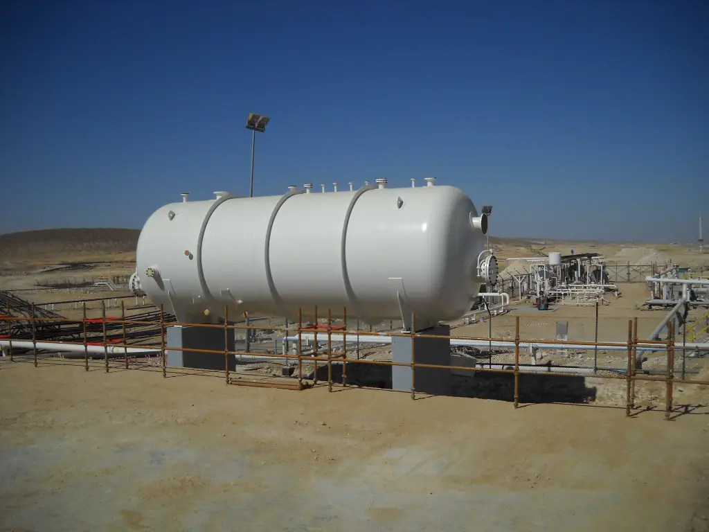
Fig. 4 shows a typical separator used in the oil and gas industry.

Nice article.However the fig-2 is not legible clearly.Can you please help with its reference .
Nice article. However, fig-2 is not legible.Can you please send me the reference?
Good information.
Send me interview questions for process engg