
A Separator is a pressurized vessel used in the exploration and production (E&P) of an oil and/or gas field to split a multi-phase well stream into a gas stream and one or more liquid streams. An example of the pressurized vertical and horizontal separators used in separation & processing include:
- Scrubber
- Slug Catcher
- Free water knock-out
Mechanical Design of the separator is done following ASME BPVC Sec. VIII Division 1 or Division 2 (Class 1 or Class 2).
The selection of Division 1 or Division 2 shall be based on both design and economic considerations. The use of the Code shall be limited to the following pressure such as:
- ASME BPVC Sec. VIII Div. 1 for 200 barg
- ASME BPVC Sec. VIII Div. 2 for 689.5 barg
If any of the following conditions apply, the vessels should be constructed in accordance with Division 2, unless otherwise specified by the Company.
- Pressure vessels operating in cyclic service, pressure or temperature-induced
- Pressure vessels that operate in the creep range of the materials of construction
- Pressure vessels where weight savings are a critical factor such as offshore or marine applications.
If either of the following conditions applies, the vessels shall be constructed in accordance with Division 2, unless otherwise approved by the Company.
- Pressure vessels with a nominal wall thickness greater than 38 mm (1½ in)
- Pressure vessels with a design pressure of 10 MPa (1500 psi) or higher.
This article aims to present an overview of a simple explanation of a 3-phase separator.
Factors for Separator Designs
Designing an “optimum” set of separators requires a balance between the desired size (volume caused by phases of liquid and gas), operating pressure, separation efficiency, space limitations (vertical/horizontal), the material of construction, fabrication method, and installation cost.
Let’s briefly look at the common design factors of a separator below.
1). Size
In general, the sizing of the separator will be carried out by the Process Engineer based on the target volume to be achieved, flow rate, density, operating temperature and pressure, and the need to precipitate droplets from gas, oil, and water. Size parameters also include process considerations such as fluid velocity, fluid hold, and storage capacity. The output size consists of diameter and length/height (seam-seam) depending on the gas capacity or liquid capacity calculation. The final option of the optimal size is the most economical.
2). Pressure
The operating pressure is usually fixed by process conditions. Therefore, in some kinds of literature, separators could be categorized according to their operating pressure.
- Low-pressure units: 10 to 180 psi (0.7 to 12.41 barg)
- Medium-pressure units: 230 to 700 psi (15.85 to 48.26 barg)
- High-pressure units: 975 to 1500 psi (67.22 to 103.42 barg)
This grouping directly affects the selection of the L/D ratio in the early stage of the design separator. The L/D ratio of the separator could be selected based on operating pressure and vice versa.
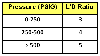
The optimum L/D ratio may refer to the above breakdown and will vary following these parameters:
- Allowable stress: affected by temperature, inside diameter, TL/TL, and material selection. It will affect the primary and secondary stresses of the entire life of the separator
- Corrosion Allowance: affected the shell, head, nozzles, and pressure-part thicknesses calculation output. It will affect the MAWP and MDMT final results
- Joint Efficiency: affected the thickness calculation, welding quality, NDE, and fabrication requirement.
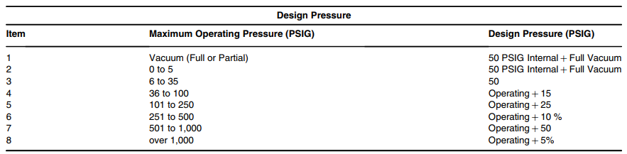
In mechanical design & analysis, it is recommended to have a suitable margin between operating and design pressure. Determination of design pressure can follow the guideline below:
3). Temperature
Operating temperature is determined based on service fluid, and ambient site temperature and considering the maximum and minimum factors, normal and the worst case caused by start-up, shutdown, operational upset, auto-refrigeration, and other sources of cooling.
In mechanical design & analysis, design temperature is used to select the proper material of construction (MOC), flanges pressure-temperature rating
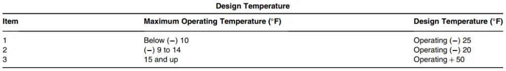
and for specific cases affects the impact test requirements (e.g per UG-20(f) and UCS-66 from ASME VIII Div.1). Determination of design temperature can follow the guideline below:
4). Orientation: vertical vs horizontal
a). Vertical Separator:
- Used for small liquid holdup or in other words; it is mainly applied when there is a large amount of vapor detected from a small amount of the light and heavy fluid (less than 10-20% by weight).
- Used for easier cleanout because of its smaller bottom area
- More easily used to handle liquid surges because of the depth of the space
- A smaller area is required especially for offshore platform cases.
- A higher climbing ladder and platform for access are required.
b). Horizontal Separator
- Used for large surge volumes because of its most efficiency large amounts of dissolved gas are present with the liquid
- The horizontal separator has a greater capacity
- Can add an additional boot to achieve liquid/liquid or vapor/liquid separation efficiency
- A less static head affects the supports geometry
- A bigger area is required but with less climbing ladder & platform.
4). Separation Process
The separation process can be described as either a 2-phase or 3-phase vessel.
- 2-phase separator: It is most often used when the fluids contain little water. It will separate gas from oil in oil fields, or gas from water in gas fields. Click here to know more about 2-phase separator design basics.
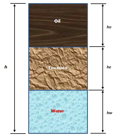
- 3-phase separators: separate the gas from the liquid phase, and water from oil. Since free water does not settle out in the time it takes for the oil and gas to separate, a three-phase separator requires a longer retention time than a two-phase separator.
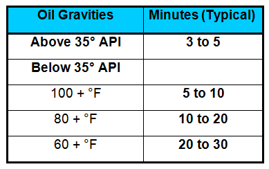
5). Retention Time
Retention time is an input parameter in determining the oil and water capacity to stay inside the separator. For a given retention time of oil and water, the procedure for establishing the diameter and length of the separator become easier.
Configuration of 3-Phase Separator (Horizontal)
3-Phase separator in horizontal orientation consists of a shell, dished ends, and mostly two saddles. From a mechanical design perspective, horizontal separators offer less wall thickness in either shell, head, and support compared to vertical separators in the same shape and size. The vertical separator will tend to be influenced by wind and seismic load resulting in greater bending stress, and deflection.
From a process design perspective, the 3-Phase separator is typically similar to the 2-phase separator, but with additional internals to handle two immiscible liquids (oil and water) rather than one liquid. In a 3-phase separator, the vessel itself should be designed to separate the gas that flashes from the liquid, as well as separate the oil and water. Therefore, in the 3-phase separator, we will find additional control devices for controlling the liquid level (LLC) and pressure (PCV).
The Simplicity of Separation steps:
Feed inlet–> hit the Inlet device –> Gravity settling and separation of bulk liquid with big droplet –> Gas exists through Mist Extractor/Mist Eliminator/Demister.
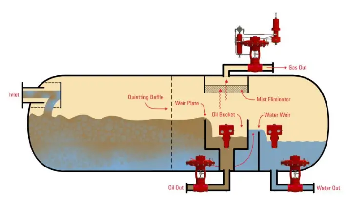
The most common configuration of a 3-phase separator used in the separation process is shown in the following sample from Kimray Inc. :
1). Horizontal 3-Phase Separator with a Weir Plate

2). Horizontal 3-Phase Separator with an Oil Bucket & Weir Plate
Internals of a 3-Phase Separator
Other information that shall be remembered while designing the separator includes separation efficiency, capacity, and pressure drop. The separation efficiency depends on the droplet size target (e.g 500-micron water and 200-micron oil) distribution in each phase of separation, hence to achieve more efficient separation, internals must be installed inside the separators.
In general, the 3-phase horizontal separator settler consists of three-zone compartments that automatically determined the internals type selection and installation. (Figure 4).
- Inlet compartment
- Settling compartment (Liquid-Liquid settling zone)
- Outlet compartment (Gas Liquid separation zone)
This device is designed according to the process requirement, and attached inside the separator by either welding or bolting connections and usually will be finalized by an internal Vendor (e.g from Sulzer) and approved by their Principal.
Internal components included:
- a). Inlet Devices
- Half-open Pipe
- Plate diverter
- Vane distributor
- Schoepentoeter
- b). Sand jetting system and drains
- c). Weir Plate (fix/adjustable type)
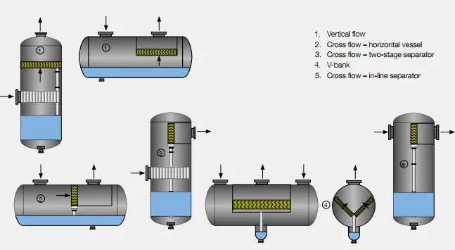
- d). Mist Extractor / Mist Eliminator / Demister
- e). Cathodic Protection (mostly Anode type to protect from H2S and CO2)
- f). Vortex breaker
As explained in an early paragraph, it can be concluded that the 3-phase horizontal separator main parts including the Head, Shell, Inlet Pipe, Inlet Device, Gas gravity separation section, Mist Extractor/Mist Eliminator/Demister, Liquid gravity separation section, Manway (for inspection and maintenance), nozzles and Saddle Supports. Fig. 5 below shows a typical general arrangement drawing of a 3-phase horizontal separator.
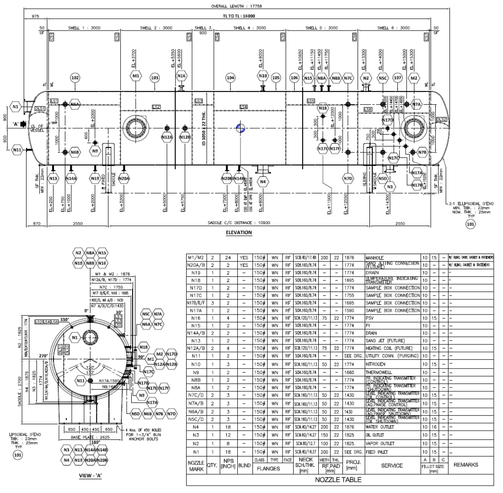
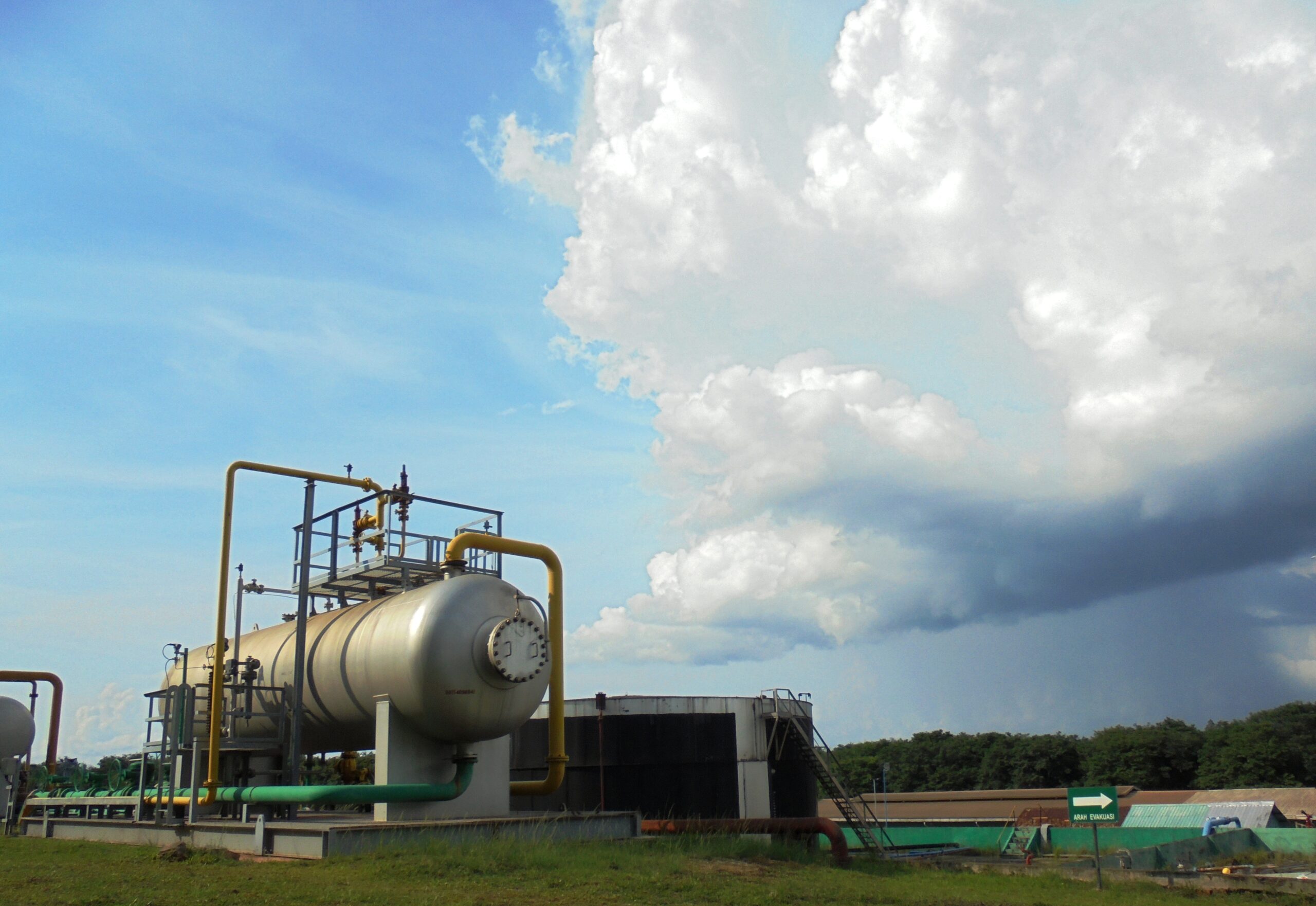
Fig. 6 below shows a typical 3-phase horizontal separator from Kaji Site – South Sumatera, Indonesia.
Conclusions
The L/D ratio is one of the factors that influence the optimal design of a separator, without neglecting other considerations, taking into account the following points:
- Process design reason
- Economical reason
- Operational reason
- Mechanical design reason
In most EPC companies, determination of the type and size of separator must be made on an individual basis, based on justification and experience in daily-routine work according to relevant guidance and specification such as GPSA, Clients Specifications, Separators Handbook, International codes/standard, etc.
Good contents.
Keep the good work for upcoming article.
Good started brother!
I hope to see more articles from you!
how do i contact you i have questions on retention time how do you determine the diameter and length of separator ?
Hi,
Please refer to API Spec 12J for your guidelines and “Surface Production Operations – Design of Oil Handling and Facilities” Vol 1 3rd Edition”, Elsevier, 2008 Handbook.
Good job continuing sharing knowledge and writing article like this.
hellow
thank for your présentation
escuse me, i can write in french, can you instand french
slt
d; safar