
A separator is simply a pressure vessel that is used for the separation of feed mixture which is from the upcoming well containing crude components. This well crude contains a gaseous, liquid mixture.
Classification of Separators
Separators can be classified through various modes; which are listed below:
1. Based on the installation:
Installation of the separator can be offshore or onshore.
- Offshore: Offshore term in which the separator is placed under the sea region.
- Onshore: Onshore term relates to the installation of a separator on the land.
2. Based on the installation location In the Plant:
Based on the location of the separator Installation, they are of the following types:
A. Production Separator: Production is situated near the well for first-stage Separation to stabilize the fluid because both of them are operating at High pressure. The stabilizing process involves Multi-stage Operation.
B. Test Separator: The test separator is also placed nearby the well simply next to or corresponding to the production separator. The test Separator function is to measure the small quantity of flow rate (for each available stream or phase) which is coming from the production separator stream using the diverting route of the production separator to the Test Separator
C. IP or MP Separator (Intermediate or Medium Pressure): This type of Separator is placed downstream to Production Separator which typically operated at low Pressure than the production separator.
D. LP Separator (Low Separator): These are used where separation is to be achieved at low operating pressure within the Separation Process.
3. Based on the Orientation of the Vessel:
The orientation of the separator vessel may be vertical, horizontal & Spherical. Selection of orientation will be based on the several factors discussed below:
Factors that affect the separator Orientation Selection:
Vertical: Vertical Orientation may be used where the plot plan provided area is small, it can be used in both application offshore & onshore applications. Vertical orientation also helps in the Pumping operation where it gives a higher NPSH Option than Horizontal Orientation.
Horizontal: Horizontal orientation is to be used where adequate space is provided & large flow rate separation is to be facilitated (achieve).
Spherical Orientation: Spherical orientation is in cases where the processing area distance equipment from each other is minimal, it is also used for ease of transportation.
4. Based on the Feed (Incoming fluid) with No of Phases available:
Generally, separators are distinguished based on phase availability. It can be 2-Phase or 3-Phase, In the case of a 2-Phase separator, the Feed fluid may contain Gas & Oil, or Gas &Water. On the other hand, a three-phase separator handles all 3-phase mixtures formed from Gas, Oil, and Water.
Important Terms for Separation Mechanism
Before starting the understanding principle of 2 Phase & 3 Phase Separator, we need to go through some important terms which are used in the Separation Mechanism:
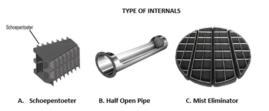
Momentum & Its criteria for the selection of Type of Internals:
Momentum is defined as the force contained within itself. Momentum also plays an important role in sizing the Feed inlet, Gas outlet Nozzle. Momentum is measured in the Pascal (Pa).
Momentum = (Density of Fluid * Velocity2) (Pa)
Criteria for Feed Inlet nozzle:
- With no Inlet Device ≤ 1000 Pa
- With Half Open Pipe as Inlet Device ≤ 1500 Pa
- With Schoepentoeter as Inlet Device ≤ 6000 Pa
Criteria for Gas Outlet Nozzle:
Gas outlet nozzle size selection shall fulfill the Momentum criteria limit ≤ 3750 Pa
Criteria for Liquid Outlet Nozzle:
The liquid outlet nozzle shall be based on a velocity that does not exceed the mark of 2 m/sec. Generally, the liquid outlet nozzle shall be taken as 2” (50 NB).
Note! – Indicated criteria for momentum are based on the D.E.P Standards. It may change from project to project, design code standards guidelines.
Mist Eliminator:
The mist eliminator is used for the removal of liquid-entrained particles in gas phases. Generally, liquid droplets size greater than 0.3 – 10 microns are captured through the mist eliminator Element. Gas-Liquid separation uses the wire mesh type of Mist Eliminator.
Weir Plate:
Weir Plate is usually used in 3 Phase Separation which is placed in a liquid separation section where oil & Liquid separate. Weir plates act as a barrier for Liquid and allow it to pass the Oil Phase through itself. Weir Plate work with the difference in density Mechanism.
Retention Time:
It is the average time period for which flowing fluid (Liquid) remains in the liquid section of the separator. It can be determined by the Liquid volume inside the vessel divided by the liquid flow rate.
Working Principle of 2-Phase Separator
2-Phase separators work on the “Principle of Momentum, Gravity Settling Theory” described below:
Inlet Fluid from the well or other sources comes at the inlet Nozzle of the separator where it takes entry into the separator.
Principle of Momentum:
Based on the momentum criteria inlet device is selected, purpose of the inlet device installation is to absorb the momentum, Minimize turbulence, re-entrapment of liquid particles in gas particles & change in direction of the fluid flowing towards the Liquid separation Section. This stated process is performed in the “primary separation section”.
Gravity Settling Theory:
This theory stated that “Settling of dispersed droplets from the continuous phase takes place if the gravitational force is greater than the sum of the buoyant force and drag force acting over the same droplet”.
Terminal velocity is the maximum velocity that can be attained by the fluid which is free-falling in the Separation Process in Liquid Separation Section treated as a secondary separation section where droplets velocity gets reduced as droplets settle within this section.
Liquid accumulation section:
It is the section that is used to provide the retention time for the liquid to efficiently separation of gas & Liquid particles from Each other; where separated gas contains drag force due to which moves upwards & passes through the Mist Eliminator.
Separated Liquid is taken outlet from the separator via the liquid outlet nozzle consisting of a Vortex breaker that keeps the fluid prevents from swirling formation.
Notes: Gravity settling theory* includes various laws within itself which are applicable based on the Reynolds number.
- For Reynolds numbers, less than 2: Gravity settling-Stokes’ law region is used which consists of the drag coefficient, and terminal Velocity, Reynolds number works as a function of the shape of the Particles, Settling of the Particles, property of behavior (Nature) of flowing fluid.
- For Reynolds numbers between 2 and 500: Gravity settling-Intermediate law region to be used.
- For Reynolds numbers between 500 and 200000: Gravity settling-Newton law region to be used.
* Gravity settling theory consists of three laws having the same functional parameter (i.e. Drag coefficient, Reynolds number, terminal Velocity) but the method to determine these parameters or equations changes according to the Reynolds number which is applicable to the law selection.
To know about the design basics of a two-phase separator visit here.
Working Principle of 3-Phase Separator:
3-Phase separator work on the “Principle of Momentum, Gravity Settling Theory & coalescence” described below:
Principle of Momentum:
The principle of Momentum remains the same as the 2-Phase separator.
Gravity Settling Theory:
Gravity settling theory remains the same as the 2-Phase Separator, but the weir plate mechanism is to be defined play an important role in oil & Liquid efficient separation.
The Weir plate works on the density difference in this lighter fluid (Less density) floating upper in the liquid separation section and the level of Liquid as the HHLL (High High Liquid Level) reaches the separator which is usually less than the weir plate height.
This enables the oil flow to be diverted (travel across the weir) towards the oil outlet in the liquid separator section.
Liquid accumulation section:
The liquid accumulation mechanism also remains the same as 2 Phase separator; in addition to that, an oil outlet nozzle is to be provided for the Oil Phase Exit from the Separator.
Click here To learn about the design basics of a Three-phase separator.
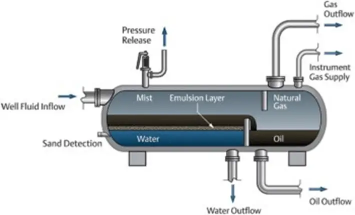
Image Credit:
- https://www.forain.net/products/filtration-separations/three-phase-separators
- https://www.costacurta.com/products/separation-technologies/separator-internals/inlet-distributors/
estoy muy agradecido estimado Anup por los artículos que publicas, que Dios bendiga grandemente tu vida!!