A Storage Tank is a piece of static equipment that is used to store products (liquids) in atmospheric pressure conditions. As there is no moving part, storage tanks are called static or stationary equipment similar to pressure vessels. However, there is a distinct difference between a storage tank and a pressure vessel; Pressure vessels hold fluid at a higher pressure than storage tanks.
Storage Tanks can be split into two types
- Site-built Tanks
- Smaller Tanks (transported to the site fully assembled)
In general, site-built tanks are designed as vertical cylinders however smaller tanks may be either vertical/horizontal cylinders or rectangular/square in shape.
Large Storage Tanks are constructed on-site, on prepared foundations as they are too large to transport.
To reduce site work and the amount of equipment required, the component parts of the tank are normally pre-fabricated or pre-formed prior to delivery.
Applications of Site-Built Storage Tanks
Site-built Large Storage tanks are used widely to store various products in the following industries.
- Refinery and Petrochemical
- Fertilizer
- Oil and Gas
- Chemical
- Water
Type of Storage Tank
Storage Tanks can be defined into three types
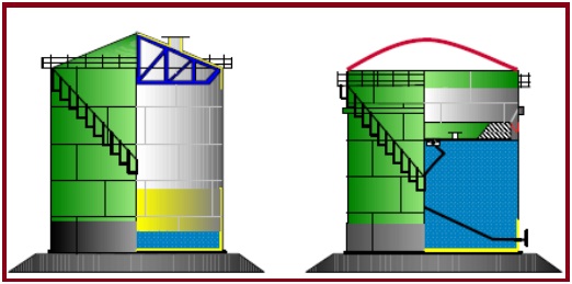
- Cone Roof Storage Tank: A Cone Roof Storage Tank has vertical sides and is equipped with a fixed cone-shaped roof that is welded to the sides of the tank.
- Open Top Floating Roof Storage Tank: An Open Top Floating Roof Storage Tank is similar to the cone roof tank in construction but with the exception that it has no fixed roof. A pontoon-type roof floats directly on the flammable liquid surface.
- Internal Floating Roof/Covered Floating Roof Storage Tank: An Internal Floating Roof/Covered Floating Roof Storage (see “red” dome) Tank is a combination of both the cone roof or dome and the open-top floating roof tank. The tank has a cone roof but with the addition of an internal floating roof or pan, that floats directly on the fuel surface.
Locating Storage Tanks
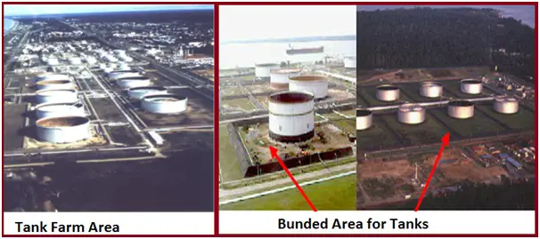
Storage Tanks are mostly located inside a Tank Farm area inside a bunded area (Fig. 2).
Bunded area is necessary around a storage tank when the potential environmental and economic risk of tank spillage is great. Its function is to contain spillage so that subsequent damage to adjacent tanks and surrounding areas can be minimized.
Component of a Storage Tank
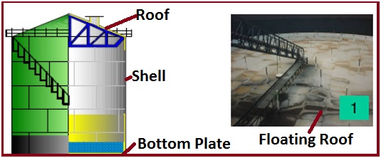
Typically a Tank consists of three components (Fig. 3).
- Tank Shell: A cylindrical portion that is resting on the bottom plate and covered by the roof.
- Tank Bottom Plate: A welded flat bottom plate that is placed beneath the cylindrical shell.
- The roof of the Tank: The fixed roof tank is mostly provided with a conical top roof. Larger diameter conical roof tanks are supported by roof structures or columns and the open-top tank is mostly provided with a floating roof.
Construction of Tank Shell
Tank shell is constructed by butt welding steel plates of specified length and width at their edges in order to form a cylindrical shell.
Construction of Tank Bottom
The bottom of a tank is constructed from flat plates. Plates are arranged with rectangular plates in the center and sketch plates (cut to suit radius) around the perimeter.
Construction of Storage Tank Roof
The top of a tank is constructed from flat plates. Plates are arranged with rectangular plates in the center and sketch plates (cut to suit radius) around the perimeter.
Type of Tank Roof Support Structures
- Fixed Conical or Dome roof tanks are provided with internal rafters or trusses (Fig. 4).
- Some larger diameter Conical or Dome roof tanks are also provided with column supports.
Storage Tank Design Standards
The main design codes for vertical cylindrical storage tanks are:
- BS EN 14015:2004 “Vertical Steel Welded Storage Tanks with Butt-Welded Shells for the Petroleum Industry”
- API 650 “Welded Steel Tanks for Oil Storage”
- DEP 34.51.01.31-Gen and DEP 64.51.01.31-Gen
Storage Tank Design Aspects
The design aspects of the storage tank can be divided into the following:
Design standards: The storage tank can be designed by using different International standards like API 650 and BS EN 14015.
Tank Shell Plate Size: Although the physical size of the shell plates is a function of the height and diameter of the tank, the actual size is also dependent upon material availability, fabricators’ facilities, and handling/logistic issues. A large plate is more difficult to form and handle, however, a large plate requires less welding during tank erection. The plate size must, therefore, be considered on a case-by-case basis to achieve the most economical design. For example, for a 10m high tank, the most practical and economical plate width would be 2.5m so as to achieve four shell courses. Plates 3.33m wide are large and nonstandard.
Storage Tank Loading Conditions:
External / Internal loads: External loads on a tank may result from adjoining piping or structures. These loads may be due to for example their static weight or as a result of thermal growth. Due to the use of relatively thin and therefore flexible steel plates, tanks have a poor ability to resist external loads and therefore measures should be taken to minimize all external loads. Methods to analyze external pipe loads can be found in API 650.
Wind / Earthquake Loads: Wind and earthquake loads depend greatly on the environmental conditions of the proposed site. Guidance on how to analyze wind and earthquake loads can be found in the appropriate design codes however particular attention should also be given to the risk of wind and earthquakes during tank erection where the full stability of the tank is not yet available and temporary facilities have to be deployed.
Loads in Storage Tank due to Pressure / Vacuum Condition: Although the maximum external design pressure of tanks is very low (6 mbar), it should be noted that tanks are inherently very poor at resisting partial vacuums. Care must be taken to ensure that vacuum breaker valves are correctly sized to prevent a partial vacuum from forming during for example liquid draw off/draining. See the below slide for an example photo of a tank collapse due to a vacuum.
Storage Tank Foundations: Although a fabricated tank is relatively light for its physical size, due to the static head from the liquid contents the overall load onto the foundations can be considerable. The design of the foundations is especially important where the ground conditions are soft or inconsistent which could result in the risk of sinking or uneven settlement which could cause the failure of the tank. To prevent this problem from occurring it is important that a soil survey of the proposed site is performed early in the project and the foundations designed to suit. This analysis may be performed by a civil engineering contractor.
On tanks where there is a potential for uplift caused by for example wind loading, the base of the tank should be anchored to the ground using foundation bolts. This is normally done by providing a concrete ring beam around the perimeter of the tank. On smaller tanks the entire foundation may be made from reinforced concrete however due to the cost, a ring beam is more economical. Uplift can also result from internal pressure bowing the floor when empty and high-pressure tanks should always be provided with foundation bolts. The area under the tank floor is typically compacted ground covered with a layer of bitumen-coated sand which helps ‘bedding-in’ of the floor plates and as a means of corrosion protection.
The layout of Storage Tanks: The layout of tanks depends upon a number of parameters such as the number of tanks, ground conditions, process duty, etc
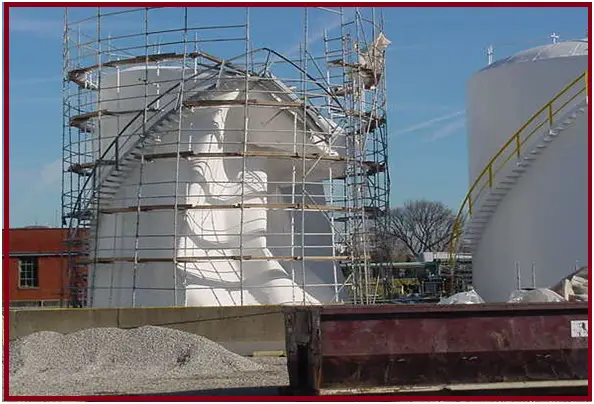
Example of vacuum collapse of Storage Tanks
This collapse occurred following the accidental draining of the contents whilst the vacuum valve was blocked by plastic tape during paint refurbishment.
Tank Material of Construction
Storage tanks are normally manufactured from the following materials
- Carbon steel
- Stainless Steel
- Duplex Stainless steel
Typical Method of Storage Tank Erection
There are four main methods of tank erection:
- Progressive
- Complete Assembly
- Jacking
- Flotation
Progressive assembly and welding: In the progressive assembly method, the bottom plates are assembled and welded first. Thereafter the shell plates are erected, held in place, tacked, and completely welded. This shall be done course by course, working upwards to the top curb angle. No course shall be added as long as the previous course has not been entirely welded. The erection and completion of the roof framing and roof plates then follow.
Complete assembly followed by welding of horizontal seams: In the complete assembly method, the bottom plates are assembled and welded first. Thereafter the shell plates are erected, held in place, and tacked, and only the vertical seams are completely welded, leaving the horizontal seams un-welded. This shall be done course by course, working upwards to the top curb angle. No course shall be added as long as the vertical seams of the previous course have not been entirely welded. The erection and completion of the roof framing and roof plates then follow. Finally, the horizontal seams are welded, working upwards from the bottom course or downwards from the top curb angle.
Jacking-up method: Some contractors employ a system of erection in which the bottom plates are completed, The top course is erected on the bottom plates, the roof framing and sheeting are completed and a number of jacks are then assembled around the structure. By means of these jacks, the completed top course together with the roof framing and sheeting is lifted to a height sufficient to insert the next lower course. The jacking method and the supporting of the partly erected shell shall have no adverse effect on the roundness of the shell. The welding is completed at each stage of lift until all courses of the shell plates have been inserted and the finished height is reached. The final operation is the welding of the bottom course to the bottom plates.
Flotation method: The flotation method is used for floating roof tanks. After the completion of the bottom plating and erection and welding of the two lower courses of the tank, the floating roof is assembled on the tank bottom and completed. The tank is then filled with water and, using the floating roof as a working platform, the third and subsequent courses are erected and welded, water being pumped in as each course is completed. Regular checks on the vertical alignment and roundness are required. This method may only be used at locations where soil settlement is very limited and with the agreement of the Principal. The predicted soil settlements of the soil investigation report shall be taken into account. A small crane is usually erected on the floating roof for hoisting the shell plates into position.
Tank Foundations:
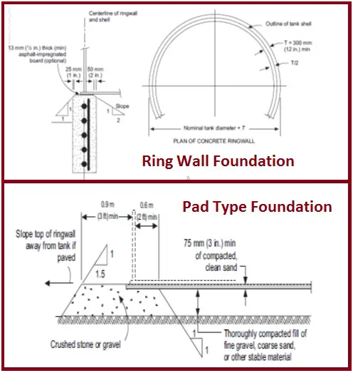
Tanks are usually supported on concrete ring wall foundation or pad-type foundation.
Venting of Storage Tanks:
Tank Venting is very important due to the low design pressure of tanks. They must consider:
- In/outflow of tank
- Thermal venting
- Number of independent breather valves
- Birds/blockage
- Roof Profile
Floating roof tanks have minimum vent losses
Consideration must be given to the maximum inflow into the tank (causing over-pressurization) and also the maximum outflow (causing partial vacuum). These may result from the action of pumps and/or process upsets such as gas blow-by from a vessel.
The type and selection of the relief valves also depend upon if there is a vapor blanket within the tank. For example, this may be a nitrogen blanket or a fuel gas blanket. Fuel gas should not be vented into the atmosphere and where practical should instead be recovered.
Tanks are also provided with simple emergency vents (blow-out covers), the purpose of which is to prevent tank damage in the event of for example a process upset condition.
Tank roofs are inherently designed to be weaker than the shell so that in the event of over-pressurization and the failure of the venting system, the roof will fail and the shell will remain intact thus preventing spillage/loss of the contents.
Small Tanks
Smaller Tanks, defined here, as those transported to the site fully assembled may be cylindrical or rectangular in shape.
They are used for many purposes such as:
- Water storage
- Fuel storage
- Settling or separation of fluids (e.g. oily water treatment)
- Lubrication oil storage
- Chemical storage
- Drains tanks
Small tanks can be supplied as individual items to the site or more commonly they are supplied on packaged skids.
Tanks may also be fabricated from concrete.
Rectangular Storage Tanks
These are very common on packaged skids as they offer the greatest volume within a confined package space envelope.
For example:
- Lubrication of oil tanks on pump/compressor skids
- Chemical storage on chemical injection skids
There is no definitive design standard for rectangular tanks and they are usually designed from first principles or “good engineering practice”.
Rectangular tanks may be made from flat or corrugated plates. Depending on the tank’s size, flat plates are normally provided with internal or external stiffeners to prevent plate deflection.
Rectangular tanks are often provided with internal partition plates so that two or more separate storage volumes are provided within a compact arrangement.
Due to a large amount of stiffening required, it is not economic to make rectangular tanks. In such cases, alternative designs, such as a cylinder, should be considered.


Very much informative
Useful information, very well presented!!
Thanks
Nice & very informative.
Beneficial information . . Many thanks
It’s good to know that reinforced concrete is specifically needed for such water tanks. I’m planning to have a new home built soon and it will be the very first home that I fully own. As such, getting to plan out its water system would be quite new to me.
We have been giving services to various process industries for their problems of erosion,corrosion,normal wear and tear and leakages. As far as tanks and piping concerned we have done floating roof repair. Due to corrosion roof plate at lot of areas got punctured and rain water centering inside. Theses tanks are petroleum storage tank of a Oil and Gas company.
By using our cold repair putty in conjunction with reinforcement sheet repaired locally wherever holes/ pits are there. Almost 30% of area of 60 mtrs dia tank roof.
The repair is intact for 4years now without any problem.
Holed/ pitted pipes also repaired in a barge mounted gas based power plant in same way . This pipe of 1.25mtr dia had worked after repair for 3years till the plant stopped operations due gas availability issues.
Please contact me for any repair and protection coatings requirement.
Dear sir;
can you send a formula for check the required thickness of shell plates for steel bolted tank
Thanks for you
It’s interesting to know about the above storage tanks and how it used for storing fuel or water. There are also several methods to erect these structures such as the jacking method. If I work in the industrial world, I would understand how different approaches and equipment are crucial to building structures properly. For me, it is also important to have trained workers that would install them properly.
It’s great that you elaborated on storage tanks and how they’re used to keep different products.
Thanks for sharing.
I am interested in what is inside a vertical crude oil storage tank. Is there anything besides the smooth walls? Pipes? Metal railings on the sides or on the fixed roof? Thanks
Great share—thank you!
Very informative post! Understanding the components and design aspects of aboveground storage tanks is crucial for safe and efficient installation.