
Why Analyze Column Piping
Columns or Towers, used for distilling raw materials (Crude Oils) are very important equipment in any process industry. Every process piping industry must have several columns. Lines of various diameters and properties (Process Parameters) are connected to Columns at different elevations. Stress analysis of all large bore lines connected to the column is required to assess proper supporting and nozzle loading. Looking at the construction of the column, it has a number of trays at different elevations. The temperature at each tray location differs based on the process. In the following article, I will try to explain the methodology followed for stress analysis of Column Piping using Caesar II.
Stress analysis of Column Piping will be discussed in the following points:
- Inputs required for pipe stress analysis
- Temperature profile creation for the column/tower
- Modeling in Caesar II
- Supporting of Column Connected piping system and
- Nozzle load qualification.
1. Inputs required for Analysis
The following data are required while modeling and analyzing column connected lines:
a) Column G.A.drawing with all dimensions, nozzle orientation, materials, etc.
b) Column temperature profile.
c) Line Designation Table/ Line list/Line Parameters and P&ID.
d) Column line isometrics.
e) The allowable nozzle load table as specified in Project Specification.
2. Temperature profile for Column/Tower
Various organizations use different methods for creating a column temperature profile. Here I will describe two methods that are most widely used.
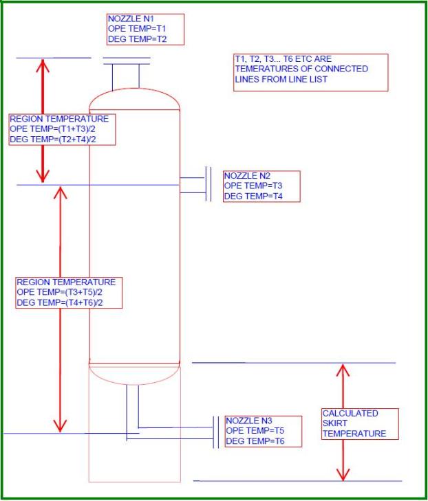
Temperature profiles for towers are normally created based on connected outlet lines. So in the P&ID mark the big size (big size means nozzle size which will make a considerable impact in temperature change) column outlet nozzles. Then write down the operating and design temperatures beside those lines from the line list. Let’s assume that there are three big sizes (N1, N2, and N3 as shown in Fig. 1) outlet nozzles in a typical tower. So temperature profile for that column can be created as shown in Fig. 1. This method is the most widely used method among prevailing EPC industries.
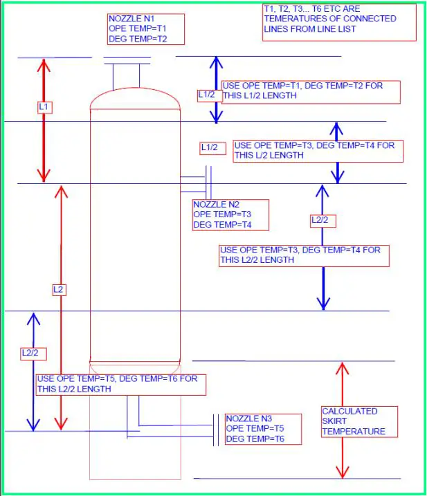
Again the temperature profile of the above tower can be generated using the method mentioned in Fig. 2. Many of organizations use this method too.
Few organizations use the operating and design temperatures mentioned in equipment GA as the equipment operating and design temperature. However, the above two methods mentioned will result in thermal growth close to reality.
3. Modeling the Column/Tower in Caesar II
All equipment modeling is almost similar. Start modeling the tower from the skirt and go up or start from the nozzle of interest and go down till the skirt as per your choice. It is a better practice to use node numbers in such a way that the equipment nodes can easily be separated from the piping nodes. I personally model equipment starting from node 5000.
Let’s start with a typical nozzle flange. So model 5000-5020 is a nozzle flange with nozzle diameter and thickness as mentioned in the equipment GA drawing. Sometimes, Vendor-GA may not be available (during the initial phase of the project), so in such situations use engineering drawing as the basis for modeling. Normally mechanical departments have a minimum nozzle thickness chart based on flange rating and corrosion allowance. Take nozzle thickness from that chart or otherwise assume nozzle thickness as two sizes higher than the connected pipe thickness. Use temperatures as mentioned in the above two diagrams (Fig. 1 or Fig. 2) from flange onwards, pressure, corrosion allowance, materials, insulation thickness, density, etc as mentioned in the reference equipment drawing.
Then, model 5020 to 10 as pipe elements with length from reference drawing (Normally nozzle projection from equipment centreline is provided, in that case, calculate the nozzle length by subtracting the equipment outside radius and flange length already modeled). Provide Anchor at node 10 with C-node at 5040. Providing node numbers for nozzles as 10, 20, etc will put all these nodes at initial nodes in restraint summary which helps me in checking nozzle loads very quickly. You can provide separate nodes if you wish. This completes the nozzle model. Now we will model the equipment.
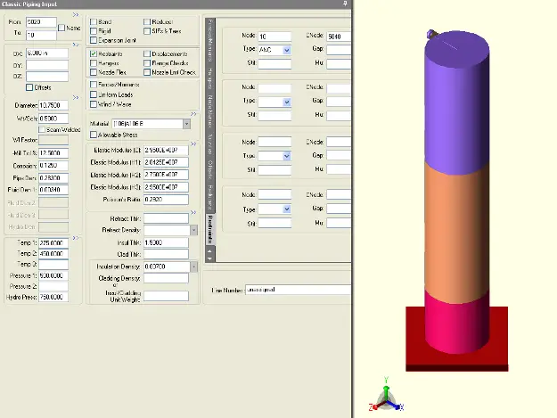
Model 5040 to 5060 as a rigid body with zero weight with length=half of equipment OD, material as provided in reference drawing, temperature as mentioned in the above figures, pressure, and other parameters from reference equipment drawing. This element will take you to the center of the equipment. From this part onwards simply model the equipment as pipe elements taking temperature profile as mentioned in the above figures. Check the diameter and thickness in the reference drawing as those values sometimes change as you proceed from the top toward the skirt. Finally model the skirt as a pipe element with temperatures calculated as mentioned in the last paragraph of this topic and pressures, fluid density, and corrosion allowance as zero. Provide a fixed anchor at bottom of the skirt. Refer to Fig. 3 for a sample model of the column. Different colors are for different temperatures.
4. Supporting of Column Connected Piping System
The pipes are normally supported by the column itself. This type of support is called cleat support or clip support. The first support from the column nozzle is a load-taking support that carries the total vertical load of the pipe. Try to place this load-taking support as near the nozzle as possible. Rest all are guide supports.
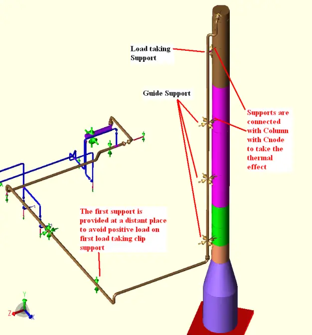
As the clips are connected to the tower body we have to model clips from the column and connect the supports with a C-node to take the thermal effect of that location. The load-bearing capacity of the clip supports is normally standardized by pipe support standards. So sometimes it may appear that the load at first load-taking support is exceeding the clip load bearing capability (This could happen if a very large size line is connected towards the top of the column, overhead lines). In those cases, we have to take 2nd support from the nozzle as a load-taking support as well.
This support has to be a Spring hanger support which will share part of the load of the first load taking the support. From that point onwards guide supports will be used based on the standard guide span as specified in the project specification. A sample Caesar II model is shown in Fig 4 for your reference to explain the clip supports. Model the clip as a rigid body with zero weight with equipment properties when inside equipment and with ambient temperature when outside equipment.
5. Nozzle Load Qualification
Allowable nozzle loads are normally provided by equipment vendors and mentioned in general arrangement drawings. Few organizations have a standard load table based on nozzle diameter and flange rating. So compare your calculated loads at the nozzle anchor point with these allowable values to find if calculated loads are acceptable or not. If loads are exceeding the allowable values modify the supporting or routing to reduce your nozzle loads. In some situations when routing change is not feasible perform WRC 537/297 or perform finite element analysis (FEA- Nozzle Pro) to check whether generated stresses are acceptable. In extreme cases send your nozzle loads to the vendor for their acceptance.
Skirt Temperature Calculation
Calculate skirt temperature following the given equation:
Average Skirt Temperature=(T-Ta)*F+ Ta; in degree centigrade
Here Ta=Ambient Temperature in degree Centigrade; T=Temperature at the top of the skirt; F=[83.6/{(K*h/t^0.5)+15.5}]; K=insulation constant=1.0 for fire brick insulation=1.6 for non-insulated; h and t are skirt height and thickness respectively.
Few more Resources for You…
Stress Analysis
Caesar II
Start-Prof
Piping design and Layout
Piping Materials
Dear Sir,
If we define temperature profile for column by following tray temperature profile of Process Data Sheet or GA drawing. Is it possible?
yes it is possible and that can be done too…
Can we take same design temp throughout column height as per GA or Mech datasheet and temperature profile for operating temp. only.
For both operating and design temperature it is better to create the temperature profile from connected lines.
calculation ragarding avarage temperaure profile of the skirt is given in the Kellogs book.
Dear Sir,
I have 2 more questions as below. I hope you can reply:
#1:
Do we need to set fluid density as “0” for long vertical pipe around column? because in case if we have very big size and heavy fluid density, it will effect to support load on EQP and spring size selection also. The fluid weight itself will not be carried by pipe support.
#2:
Is it ok to use your equation to calculate skirt temperature? How can I trust this equation?
1. In my opinion you have to take the fluid density for support load and spring selection as that fluid will always be there inside the pipe run.
2. That equation for skirt temperature calculation is based on some code (mostly ASCE or UBC) and universally accepted. So you can use this equation.
Dear Author,
As far as I have conceived from the this is that equipment has been modeled as a Pipe. One of the demerits in such a method is that Caesar starts evaluating whole equipment which is not our objective.
In my opinion, equipment should be modeled as a rigid element with zero weight, so that it does not get evaluated as per the specified code say B 31.3.
Waiting for a response from your side on my query.
What are the units for “h” & “t” in skirt temp. calculation formula.
F=[83.6/{(K*h/t^0.5)+15.5}]
What are the units for “h” & “t” in skirt temp. calculation formula.
What are the units for “F” ?
Sir,
how do we consider start up and shut down cases of column with connected piping
Dear sir
can you provide me information on how to do modelling in CAESARII.
Dear Anup,
Can you provide the analysis of air fin cooler?
Dear Sir,
Request you if you can help on explaining what is the sway effect on column line?
How it is incorporated in Column line analysis?
Do we model Column as rigid element and then input the wind displacement at different elevations?
Hi every body
Could you please, explain clearly, what is the procedure of modeling vessel clips?
For example which nodes shall be CNode?
It would be very useful if you issue an example please.
Thank you in Advance
Ari,
modeling => connect node from center of vessel (node 1) to location as vessel clip attached (node 2), length = D_vessel/2, all property & temp. & pressure profile same as vessel, rigid weight = 0.
=> connect node from location as vessel clip attached (node 2) to location as pipe need supported (node 3), temp ambient, pressure =0, insulation thickness=0, fluid density =0, mat’l property same as vessel, rigid weight =0.
=> add restraint on pipe then CNODE as end of vessel clips (node 3)
Thank you Anup Sir, for this very useful article.
I was needed same clarification as by Ari, Thank you Sodsai.L.
Viewer, Don’t go with a benchmark of a stress analysis theory. very baby is different as you see. In above model there is big mistake to correct, never clip the first support on the pipe rack as shown in this case. also never come to conclusion with one model like this. you have to do three type of stress analysis one for pressure vessel profile, one for piping tie-in on the top without attaching pressure vessel pipe supports, one for piping with tie-in connection and pipe supports attached to vertical pressure vessel.
Three analysis you will notice a big difference of thermal stress, piping loads and nozzle loads, if pressure vessel thermal displacement is more then 6inch and loads on the support are more then 30,000lb go for constant supports.
Understand the fundamental of how stress is acting with different load cases and process condition, NEVER believe with benchmarks.
Hi,
There is no mentioning that the first support is connected to pipe rack. Infact the column here refers to the equipment (Distillation colomn or something) and not steel column.
In those cases, we have to take 2nd support from the nozzle as a load taking support as well. This support has to be a Spring hanger support which will share part of the load of the first load taking the support.
Can it be elaborated more with CII example shots…