
Proper bolt loading is essential for ensuring proper sealing of the flanged joint to avoid flange leakage problems. This bolt load for gasket sealing and flange seating is provided by Flange Bolt Torque. So Flange Bolt Torque calculation should be done with utmost care for the proper functioning of the flanged joints. However, there is no direct method of measuring this load on the gasket, but the applied torque on the flanged bolts can be measured and controlled. In this article, we will learn the basics of flange bolt torque calculation and some of the typical torque values in a chart format.
What is Flange Bolt Torque?
Torque is a measure of rotational force applied to a bolt or screw, and it plays a vital role in achieving the correct clamping force on flanged connections. Proper torque ensures that the flange bolts are neither too tight nor too loose, which is essential for preventing issues such as leaks, flange separation, and joint failure.
When a flange is bolted together, the torque applied to the bolts compresses the gasket or sealing material between the flanges, creating a tight seal. This clamping force must be carefully controlled to maintain the integrity of the seal and ensure the system functions correctly under operating conditions.
Flange Bolt Torque Calculation Formula
Bolt Torque is the twisting or turning force applied to tighten the nut on a bolt. Using a calibrated torque wrench (Manual or Hydraulic Torque Wrench), flange bolt torque can be measured during flange assembly. This torque creates an axial force in the bolt. More torque is applied the nut stretches the bolt more and the load on the gasket increases. Bolt torque is calculated for a flanged assembly using the following equation.
Applied Torque, T= (k∙f∙d)/12 in FPS Unit
Where:
- T=Torque in ft-lb
- k=Dimensionless nut factor or tightening factor
- f=axial force in pounds
- d=Nominal bolt diameter in inches
In the Metric System,
Torque Applied, T = (k.d.f)/1000
where
- T = Torque in N-m
- f = Bolt load in N
- d = Bolt diameter in mm
- k=Dimensionless nut factor or tightening factor
Nut Factor on Flange Bolt Torque Calculation
The nut factor or tightening factor (k) is a “modified” friction factor. It is an empirically derived correlation factor that includes the impact of friction. The nut factor depends on various factors including the following:
- Geometric factor – shape or type of threads
- The friction of the nut against the bearing surface of the flange
- Friction between threads of nuts and bolts
- Bolt diameter
- Bolt material
- Assembly temperature, etc.
Because of so many factors, the applied torque between the two fasteners always varies between 20-30%. A small change in the nut factor/tightening factor results in large changes in the gasket load. For same torque values with a 0.1 nut factor would produce twice the axial force as a 0.2 nut factor. That’s why well-lubricated bolts, nuts, and washers are always preferred.
Factors Affecting the Applied Torque
The required torque in a flanged joint is dependent on various factors:
- Nut and bolt size, class, and material
- Burr of the nuts
- Lubrication
- Dust, chips, and dirt on bolts and nuts
- Notches
- State of the flange surface on which to rotate
- Gasket material and thickness
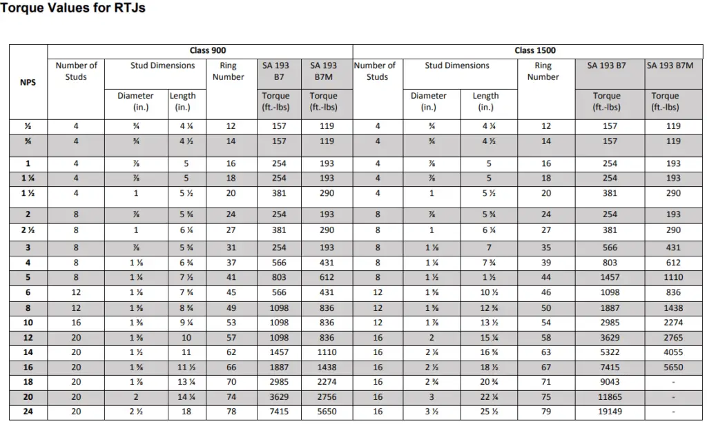
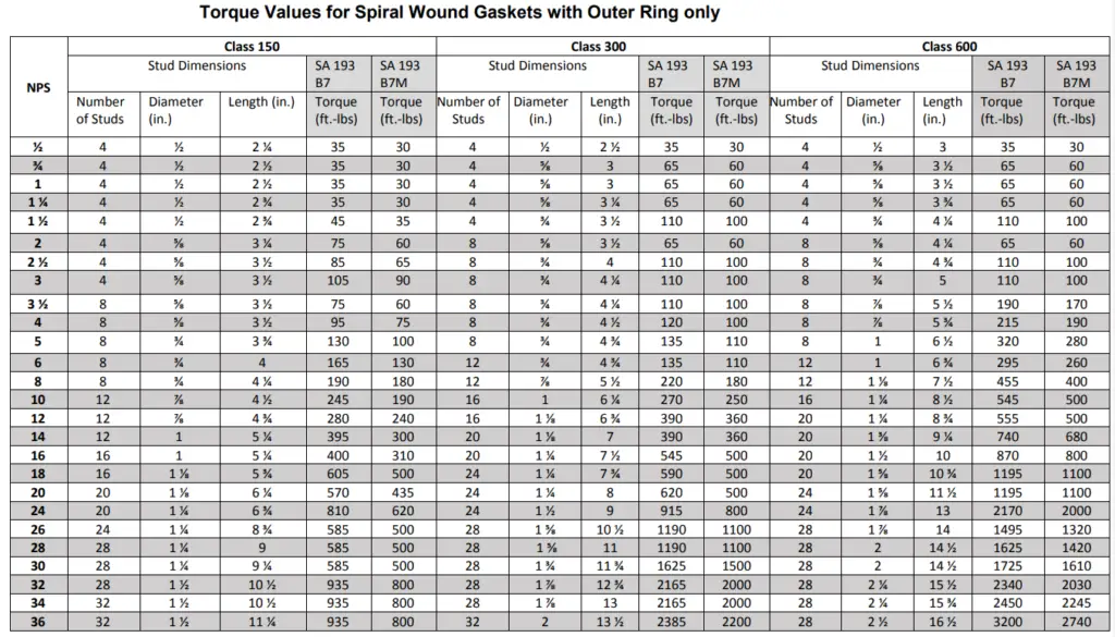
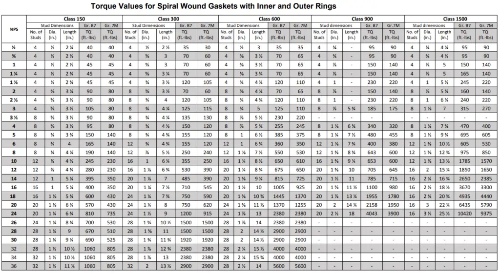
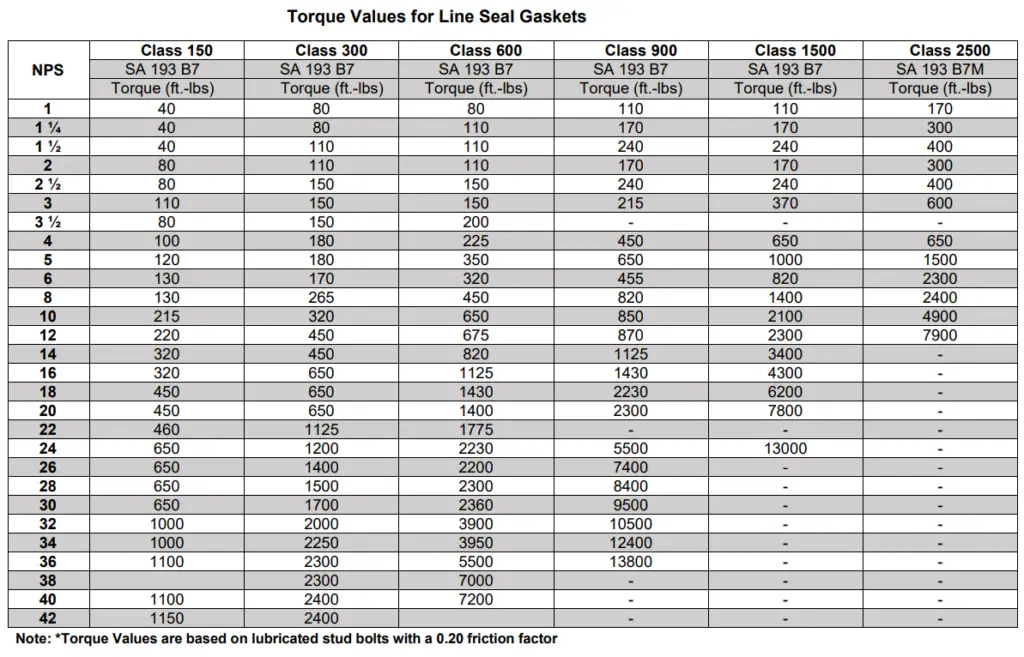
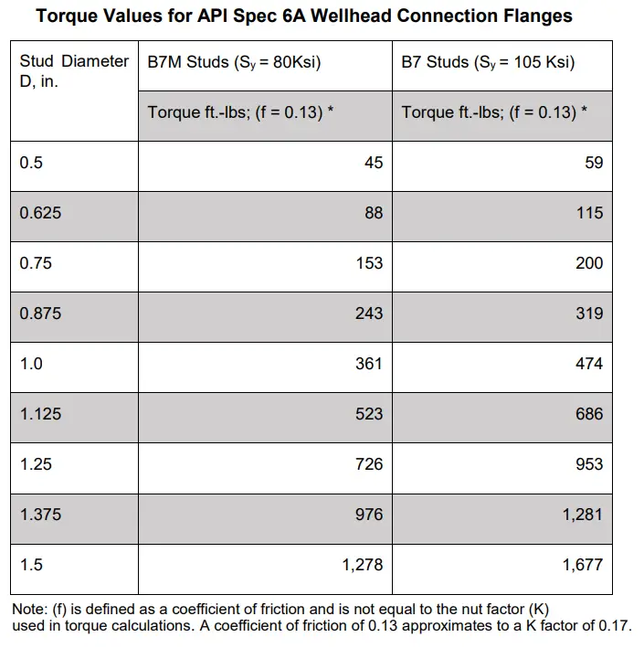
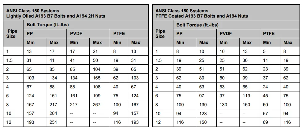
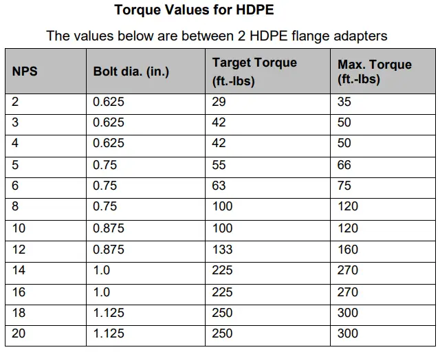
Pipe Flange Bolt Torque Chart
Even though flange blot toque calculation is possible, they are normally selected from the pipe flange bolt torque chart. The entire bolt pattern shall be tightened at least three times around the flange at 30%, 70%, and 100% of the torque value. For bolt diameters greater than 1.25”, Hydraulic Tensioning is recommended to achieve more uniform gasket stress. The following images provide some typical Pipe flange bolt torque charts.
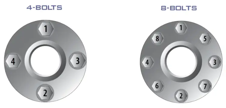
Flange Bolt Torque Sequence
The first step in flange bolt torquing is to examine the flange alignment and inspect the nut, gasket, stud, or bolts. Here’s a simplified version of the bolt-torquing sequence:
- Finish All Pre-Checks: Before you start tightening, make sure everything is checked.
- Tighten Bolts in a Criss-Cross Pattern: Follow the criss-cross pattern for tightening and make sure to use three passes with the final torque value.
- Pass 1: Tighten bolts to 30% of the final torque. Check that the gasket is compressing evenly.
- Pass 2: Tighten bolts to 60% of the final torque.
- Pass 3: Tighten bolts to the full final torque (100%).
- Final Check: After the three passes, go over the bolts again using the final torque in a criss-cross pattern until the nuts don’t turn anymore.
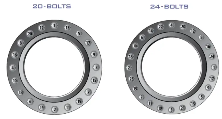
The following images (Fig. 8 to Fig. 10) show the torquing sequence with respect to the number of bolts:

The following table provides the required flange bolt torque sequence
| Flange Bolt Torque Sequence Table (4-bolt to 32-bolt) | |
| Number of Bolt / Stud (Refer to ASME B16.5 with Respective Pressure Class) | Required Bolt Tightening Sequence |
| 4-bolt Flange | 1,3,2,4 |
| 8-bolt Flange | 1,5,3,7,2,6,4,8 |
| 12-bolt Flange | 1,7,4,10,2,8,5,11,3,9,6,12 |
| 16-bolt Flange | 1,9,5,13,3,11,7,15,2,10,6,14,4,12,8,16 |
| 20-bolt Flange | 1,11,6,16,3,13,8,18,5,15,10,20,2,12,7,17,4,14,9,19 |
| 24-bolt Flange | 1,13,7,19,4,16,10,22,2,14,8,20,5,17,11,23,6,18,12,24,3,15,9,21 |
| 28-bolt Flange | 1,15,8,22,4,18,11,25,6,20,13,27,2,16,9,23,5,19,12,26,3,17,10,24,7,21,14,28 |
| 32-bolt Flange | 1,17,9,25,5,21,13,29,3,19,11,27,7,23,15,31,2,18,10,26,6,22,14,30,8,24,16,32,4,20,12,28 |
Hot Torquing
When the tightening of all bolts of a flanged joint is performed at the operating temperature, the process is known as Hot Torquing. For flanges that are known to leak at elevated temperatures due to gasket relaxation, the Hot Torqueing method is applied. It is normally performed when the temperature of the flange or the bolts is between 150°C and 230°C, or within 24 hours of a unit start-up if the joint temperature remains below 150°C.
Flange Bolt Torquing Guidelines
The following guidelines should be followed
- Flanges and Gaskets must be inspected prior to torque application.
- All working surfaces must be cleaned and lubricated properly.
- Gaskets must be new, Re-use is normally not permitted.
- Flange Bolt torquing must be done following the appropriate flange bolt tightening sequence. To know more about the flange bolt tightening sequence, Read: Flange Bolt tightening Procedure/Bolt Tightening Steps
Dear thanks.
Is it possible to include a torque table for non-metallic gasket?, example Garlok
Regard
shall we consider same torque requirements for PTFE and EPMD as in line seals chart?
Hi Anup,
Would you please advise how I can calculate the total force on the bolt for calculating tightening torque.
I want to calculate the total force acting on bolt and tightening torque required. Please see below my calculation and advice .
Calculation of Tightening Torque on the Bolt of Butterfly Valve.
A. Calculation of Axial Force on bolt:
(i) Considering Maximum Working Pressure 25PSI
Type of Valve Unit Data Remark
Butterfly Valve, NB Inch 60
Ring type, flat face, Counter flange ID,D, inch Inch 60.19 Ref. Texas Flange Drawing
Maximum working Pressure psia 25 Ref. Valve Data Sheet
Atmospheric pressure at wok side psia 14.7
Maximum Pressure psig 10.3
Bolt material A 193 Gr. B7
Bolt diameter, d Inch 1.75 Refer Table 2D, AWWA C207
No. of bolts Nos. 52
Flange Internal Area, A inch2 2845.37
Total force acting on Valve disk when the valve is closed, F pbf 29307.30
Total axial force acting on bolts, F pbf 29307.30
Factor for non lubricated bolt.K 0.20
Tightening torque acting on the bolt, T = K*d*F inch-lb 10257.55
Tigtening torque acting on the bolt, T = K*d*F ft-lb 854.80
(ii) Considering maximum force (momentum) acting on Valve Disk when the valve is closed
Type of Valve Unit Data Remark
Butterfly Valve, NB Inch 60
Ring type, flat face, Counter flage ID,D, inch Inch 60.19 Ref. Texas Flange Drawing
Maximum working Pressure psia 25 Ref. Valve Data Sheet
Atmospheric pressure at wok side psia 14.7
Maximum Pressure psig 10.3
Bolt material A 193 Gr. B7
Bolt diameter, d Inch 1.75 Refer Table 2D, AWWA C207
No. of bolts Nos. 52
Flange Internal Area, A inch2 2845.37
Flange Internal Area, A ft2 19.76
Factor for non lubricated bolt.K 0.20
Maximum Gas flow rate through the valve cfm 160000.00 Ref. Valve Data Sheet
Density of gas lb/ft3 0.08
Mass flow rate, m lb/sec 204.00
Velocity of flow, V ft/sec 134.96
gc lb.ft/lbf sec2 32.20
Axial force acting on the bolts, F = MV/gc lbf 855.00
Tightening torque acting on the bolt, T = K*d*F inch-lb 299.25
Tightening torque acting on the bolt, T = K*d*F ft-lb 24.94
Looking forward for your advice.
V/r
Sankar Ghosh, PE
Hi Anup,
Good Afternoon.
I noted your calculation. Would you please advise how I calculate the tightening on the bolt A193 B7, diameter 1.75 inch for 60 ” NB flange . The parameters are as follows:
1. 60 inch ring type flange rating 150 lb as per AWWA C207 for 60 inch flanged butterfly Valve
2. Working Pressure 3 psia-20 psia
3. Working temperature : 300 deg F
4. Gas Flow rate 160,000 CFM
5. Bolt Material A193 B7.
Please advise how I can calculate the axial force ( F) acting on bolt.
Looking forward
V/r
Sankar Ghosh, PE
Please refer ASME BPVC VIII section 4.16, you will get your answer there
30inch pipe
75mm nut size
how much torque pressure in psi give me please
as per my understanding the formulae written as per ASME PCC-1 ,appendix-K is not justified and correct. we shall calculate flange bolt torque as per ASME sec. VIII div. 1 .
Hi Anup,
I referred many standards for the body-bonnet bolt tightening like API 6A annex H, ASME PCC 01, ASME BPVC VIII and VDI 2230. But I didnt come across one point which i am more eager to know. That is there any way to determine the effect of PCD on bolt tightening torque ?
If Yes, can you please provide me the relation of the same, it will be highly appreciated.
Need to discuss the solution for bolt tightening with nut.
Hi Anup,
I have a series of cast iron flanged end y strainers that I need to calculate torque values for. They differ in size and model numbers which means they each have different pressure and temp ratings for steam and liquid water. Could you advise me where to look for these answers or how to calculate them myself?
Thanks,
Steve