What is a Piping Network?
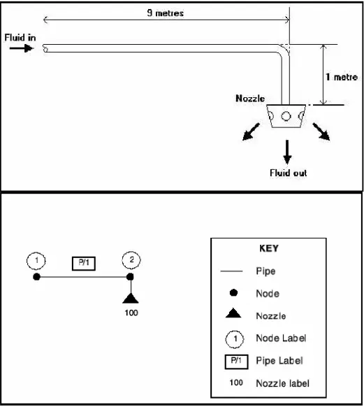
In general, piping networks consist of a number of piping components (Pipes, Ducts, Pumps, Valves, Filters, Orifice Plates, Fixed Pressure Drops, and Nozzles) all connected together. The points at which the components may be joined to other components are referred to as nodes. Consider, for example, the simple system shown below, which consists of a single pipe with a nozzle on one end. Fluid enters the open end of the pipe and is discharged through the nozzle.
This network can be represented schematically by the diagram shown below (Fig. 1)

Labeling Diagram of a piping network
Notice how the pipe, nozzle, and nodes have each been given a label. When preparing a network for simulation every component and every node must be given a label that identifies it uniquely. The production of a fully labeled schematic diagram is an essential part of any simulation. Labels may either be tagged or untagged. Tags can be used to make labels more meaningful, and to allow sections of large networks to be more easily identified. In our schematic diagram, we have labeled the pipe as P/1(tagged label), the nozzle as 100 (untagged label), and the nodes as 1 and 2(untagged label).
Inlets and Outlets of a piping network
In the drawing of a network, each pipe, pump, valve, and filter component should have two nodes (one at each end). One of these nodes is designated the component’s input node and the other is designated its output node. Note that fluid does not necessarily flow from the input node to the output node.
Hydraulic Calculation of the piping network
- -Sizing calculation.
- –Pressure Drop calculation.
- -Adjust/Regulate/Control the piping systems.
Pipe Sizing Criteria:
- Pressure drops.
- System requirements and contract (client) recommendations.
Fluid Velocity Criteria:
High velocity in piping systems increases the following effects:
- -Pressure Drop.
- -Pipe corrosion.
- –Water hammer.
- -Noise (sound) emission.
On the other hand, low velocities increase pipe diameter (Increase the total cost) and also increase the possibility of illuviation (Sedimentation) in a piping system.
For fluid velocities of different systems, it is better to refer to the piping handbooks.
Pressure drop Criteria:
Generally, it is preferable to reduce the pressure drop in the piping system as far as possible because :
- -To decrease the size of the pump or compressor (Cost reduction).
- -To reduce the initial pressure (i.e. in case of gravity flows).
- -To decrease energy losses.
- -To reduce the downstream velocity of gases and the related corrosion and noise emission.
For admissible pressure drop for different media systems, it is better to refer to piping handbooks (For example for Water it is 2.5 m/100m and for natural gas, the total pressure drop shall be less than 10% of initial pressure).
System requirements & contract (client) recommendations
Sometimes we must meet some conditions in Terminal points/input/output points (according to technical matters, contract specifications, or client requirements). For example:
- For a long water piping system with gravity flow maybe it is needed to use velocities less than what was mentioned before.
- For a system with predefined flow characteristics in the inlet and outlet points (flow characteristics have been defined in terminal points).
- Climatic conditions.
Pipe sizing calculation

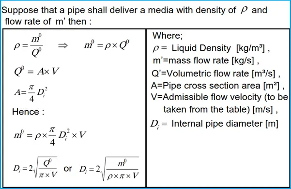
After the calculation of the pipe inside diameter, according to the pipe schedule and pipe dimension standard, the suitable nominal diameter is selected.
Now the actual velocity of the medium in the pipe shall be calculated according to the selected nominal diameter.
Note: The metal pipe dimensions are basically according to ANSI B36.10 or API 5L. Also, for the PE pipe please refer to DIN 8074.
Steady Single Phase Compressible Flow in Piping
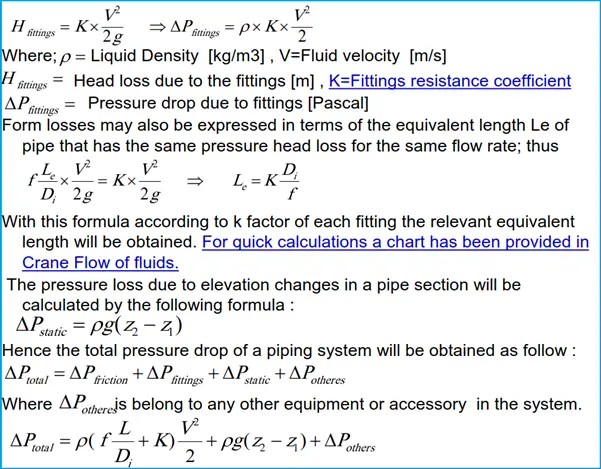
According to Darcy formula, the friction head loss in an incompressible fluid is calculated from the following formula:


Pressure losses that occur in piping systems due to bends, elbows, joints, valves, and so forth are called form losses. For the recommended values of local flow resistance coefficients (K-factors) please refer to Crane Flow of Fluids.

Sequence of simulation
- -Prepare a pipe route (single line) according to the technical specification and system requirements.
- -Specify the process characteristics of flow in I/O points (Regarding the Terminal point data, consumers, and system component specifications)
- -Specify each pipe section and its node numbers and extract its relevant information from the pipe route and technical specifications (length of the pipe section, its start & end nodes identification, its fitting, fixed pressure drops,…).
- -Calculate the pipe size of each pipe section.
- -Calculate the total pressure drop in each pipe section. It is noted that the output pressure of each pipe section shall be used as the input pressure of the next pipe section. The total pressure drop is the difference between the inlet pressure pipe section and the outlet pressure of the farthest pipe section.

Above information is very useful for understanding from basic things. Thank you so much for sharing this
Thanks for your information.
For considering hydraulic calculation, if obstruction sprinklers either under beams or air duct are required to be added, should I address all sprinklers flow simultaneously within the designed AMAO? Since the number of sprinklers maybe doubled. Thanks.
Information provided is very useful. I will welcome information about surge analysis .
RKGarg