
Reboiler Control is very effective to a distillation column as it prevents the distillation column from disturbances occurring in the heating medium. Reboiler controls include reboiler temperature control, reboiler level control, reboiler duty control, reboiler steam flow control, etc.
The most suitable variable for regulating a column is boil-up. Boil-Up is controlled to achieve the desired product quality normally in the bottom section.
When the boil-up rate is kept constant, the reboiler control valve is usually manipulated by a heating medium flow controller. When the boil-up is regulated to achieve desired product purity, the reboiler control valve is directly or indirectly manipulated by a tray temperature, a product analyzer, or the base level. Indirect manipulation is performed by a cascade controller that varies the set point of the heating medium flow controller. The flow controller, in turn, manipulates the reboiler control valve.
Reboiling with a Condensing Fluid
Example of this type of reboiler is steam reboiler and refrigeration reboilers. The control valve may be located either at the inlet line or at the condensate outlet line as shown in Fig. 1.
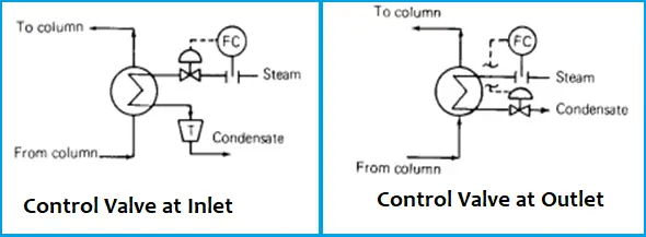
When the control valve is located at the inlet of the reboiler, the heat transfer rate is controlled by changing the reboiler condensing pressure & therefore condensing temperature. When a higher boil-up is needed the valve opens and increases the reboiler pressure which increases the reboiler temperature difference, which in turn increases the boil-up rate.
When the condensate flow rate is manipulated, vapor always condenses essentially at the supply header pressure. Heat transfer rate is changed by partially flooding the reboiler with condensate & thereby varying the surface area available in the reboiler for condensation.
Location of Control Valve (Upstream Vs Downstream of reboiler)
The location of the control valve has a major impact on the efficiency, performance of the whole column. There are several pros and cons for each location which are as follows,
1. Controlling the inlet valve immediately changes the vapor flow which in turn changes reboiler pressure & the heat transfer rate. On the other hand condensate outlet valve has no direct influence on vapor flow rate. Condensate flow determines the condensate level & this level changes slowly. Because of this slow response, manipulation of reboiler vapor flow is a far better means of control than condensate flow control.
2. The condensate outlet control scheme, sometimes the control valve in the condensate line can’t handle the amount of condensate the reboiler can generate, a maximum vapor flow may be reached with condensate still covering a portion of tubes and the pressure difference between the reboiler and the condensate system is small a condensate pot with pump may be needed to overcome the problem.
The converse of this problem can also be troublesome when the reboiler is unable to condense vapor as fast as the condensate valve removes the liquid, the liquid seal in the reboiler may be lost & vapor will pass into the condensate system which results in a dramatic loss of heat transfer also causes hammering in the condensate system. This problem can be overcome by the above control scheme (Fig. 2-A) without a pump. The other best arrangement is as shown in Fig. 2-B
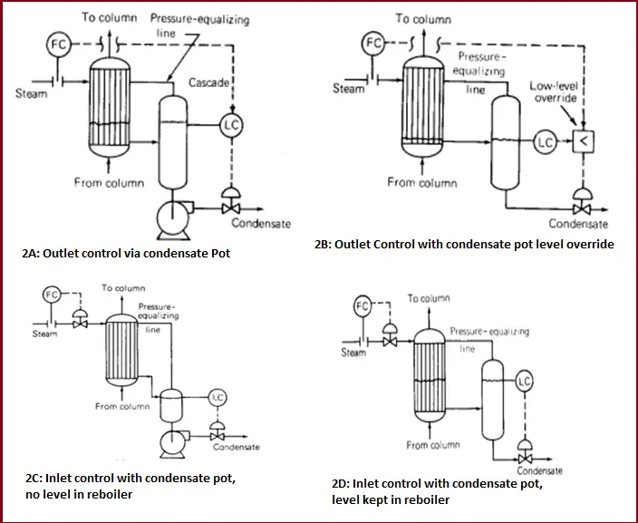
Here the flow controller (Fig. 2B) normally controls the condensate valve, with the level override cutting in whenever the level falls too low.
3. The condensate outlet scheme permits reboiler operation at a higher pressure because it eliminates the pressure drop at the inlet control valve. It is a major advantage when refrigerant vapor is the heating medium. As refrigeration compressor interstage pressures are often set to “ride’’ on the reboiler condensing pressure. The higher the pressure the lower the refrigerant compressor power consumption.
4. In a steam-heated reboiler, the vapor inlet control scheme minimizes the reboiler tube wall temperature. This reduces reboiler fouling (process side) and lowers thermal stresses at the reboiler heads.
If fouling becomes a serious concern, it is often desirable to keep the reboiler wall temperature as low as possible. The arrangement in Fig. 2C fully utilizes the reboiler area to automatically minimize the condensation temperature.
5. A smaller control valve is required with the condensate outlet scheme.
6. The vapor inlet scheme may be troublesome when the excess surface area is available at the reboiler. During initial operation, the inlet control valve closes to reduce condensing temperature (Q=UA ΔTlm) UA is large, where Q is heat duty, U is overall heat transfer coefficient, A is reboiler area, ΔTlm is log mean temperature difference) & condensing pressure. If condensing pressure falls below condensate header pressure(e.g. with steam reboiler using 15 to 35-PSIG steam), it will be impossible to remove the condensate. The condensate that is not removed will be built up into the reboiler and floods some of the tube surfaces. The point at which condensate will start building up can be calculated. With condensate tubes partially flooded any further variations in steam flow to the reboiler will affect both the delta T in the reboiler and the fraction of tube surface until a new equilibrium is reached. These two often interact, giving rise to slow, sometimes erratic responses. The steam trap will offer a little assistance with control of the condensate level. Further, if the reboiler load changes are sudden, the above-manipulated equilibrium will be difficult to establish or sustain as well as the hunting of the control valve happens.
To overcome this problem a submerged condensate pot is often installed instead of the stream trap as described earlier. An alternative remedy is replacing the steam trap with a level condensate pot (refer to Fig. 2D). By varying the level control set point the surface in the reboiler can be adjusted so that the reboiler operates at a pressure high enough to ensure condensate removal at all times without a pump.
Note: The bottom of this drum is located below the bottom of the condensing side of the reboiler otherwise, “dry’’ reboiler operation at high rates will not be possible and reboiler capacity will be reduced.
7. Steam traps are considered generally troublesome because they are prone to plug or stick open. The use of a steam trap is considered a disadvantage. The vapor inlet scheme in Fig-6 can overcome this problem.
8. In the vapor control scheme, during the reboiler turn down flow rate across the valve changes from non-critical to critical. As the boil-up falls, so does the absolute pressure downstream of the valve. When the ratio of u/s & d/s pressure exceeds a critical value, critical flow is established through the valve.
To prevent this problem, it’s best to design the system to operate over its normal range in one flow or another. A level condensate seal pot can keep up the d/s pressure during turn-down conditions. Alternatively installing a pressure regulator u/s of the flow controller can lower the pressure u/s of the inlet valve.
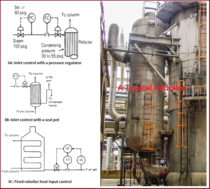
9. With the condensate outlet scheme (Fig. 3A), condensate accumulation in horizontal shells at turned-down conditions can flood most of the exchanger baffle windows and restrict vapor passage through the window. This may result in liquid hammering.
Based on the above points it has been observed that the vapor inlet scheme is more effective in reducing disturbances in the steam supply than the condensate outlet scheme.
10. The condensate outlet scheme can destabilize thermosiphon reboiler operation.
11. Corrosion due to the condensate level maintained in the reboiler often occurs with the condensate outlet scheme. The layer of rust on the steam side of the reboiler clearly indicated the level at which the condensate ran.
Loop Seal
In some low-pressure steam reboiler, the condensate pot is replaced by a loop seal (see below figure). Increasing the steam flow rate to the reboiler raises the pressure in the shell of the reboiler, which in turn lowers the liquid level in the reboiler & exposes more tube area. The behaviors of this system are similar to that of the condensate outlet scheme. The height of the liquid in the loop is typically 5 to 10 ft. This arrangement (Fig. 3B) can be troublesome when the reboiler heat load or the steam mains pressure tends to fluctuate, and it is usually best to avoid it.
Reboiling with Sensible Heat:
Sometimes hot oil or hot gas is used for reboiling purposes. Heat input is regulated by changing the heating medium flow through the reboiler, which in turn varies both the heat transfer coefficient and the temperature difference across the reboiler. The reboiler responses depend on whether the heat transfer coefficient variation or variation is a dominant factor affecting heat input. Generally, at high reboiler ΔT, the heat transfer coefficient effect dominates while the ΔT effect becomes more dominant at low reboiler ΔT.
Direct-fired reboiler:
This type of reboiler (Fig. 3C) is basically used in refineries. Usually, these are fires with a mixture of gases vented from various units supplemented by natural gas. The problem that frequently happens with direct-fired reboiler is heat input changes with fuel gas composition. For this reason, it may be difficult to control the fuel flow rate to the furnace, and heat input control may be necessary.
Correction for composition can be done using a factor (heating value √S.G), known as Wobbe Index, where SG is the gas-specific gravity. For hydrocarbon mixture, the Wobbe Index varies linearly with SG, and measurement of SG is sufficient for composition correction. The below arrangement shows the control system using Wobbe Index.
The density meter should be installed directly in the fuel gas line, downstream of the knock-out drum, and any points where fuel gas streams are added and where it would be unaffected by vibrations.