Reinforcing Pad, Reinforcement Pad, RePAD, or RF Pad is a donut-shaped pad that goes around the branch of a branch joint to add strength to the joint. It resembles a round metal washer that has been bent to conform to the curvature of the pipe.
With the increase in pipe size, the cost of branch connection fittings increases. Sometimes, such fittings are not readily available as standard pieces. So, it is a standard method to fabricate the tee by cutting a hole in the header and welding the branch in the pipe. However, the section where the straight pipe is punctured becomes a weak section due to the presence of that hole. So to handle the pressure and reduce the stress concentration in that region, the thickness is increased locally in the form of a reinforcement pad, or RF pad.
A similar situation arises for Pressure Vessel Nozzle Connections. To increase the pressure and load-carrying capability of the equipment nozzles, the RF pad is welded. These reinforcement pads provide additional strength and capability to the pipe or nozzle as per application.
Why is the Reinforcement Pad or Repad required?
RePADs, or RF Pads, are plates used to reinforce components and/or nozzles by increasing the thickness local to the component in high-stressed zones. These are made from the same size and material as the pipe header to which they are welded. On pipes or pressure vessels, holes are made in the form of a nozzle or branch intersection, and thus the parent pipe or vessel is weakened and high-stress zones are created. Hence, it is obvious to compensate for this weakness with a reinforcing pad to reduce the possibility of failure, as it strengthens the piping branch connection or the pressure vessel nozzle. The main functions of RF pads can be summarized as follows:
Added Reinforcement:
RF pads provide structural support to piping systems and equipment nozzles. They help distribute the stress and load from the nozzle or pipe across a larger area of the equipment, reducing the risk of localized stress that could lead to cracks or failures.
By shielding the underlying equipment from direct contact with piping or other elements, RF pads prevent damage from abrasive or corrosive substances. They also help protect against thermal stresses and mechanical vibrations.
Improved Stress Distribution:
RF pads are designed to mitigate the impact of thermal expansion and contraction. They help distribute the mechanical stresses generated by temperature fluctuations, which is crucial for maintaining the integrity of piping and equipment over time.
Maintenance and Longevity:
RF pads can extend the life of both the nozzle and the piping system. By minimizing wear and tear on critical components, they reduce the need for frequent maintenance and replacement.
Uses of Reinforcing PAD
The main applications of RF pads are listed below
1. Normally Reinforcing pads are used at stub-on and stub-in branch connections if required per the line list or if required per the branch chart in the piping material specification. By using reinforcing pads, it is not required to strengthen the complete header pipe. Clause 304.3.3 of ASME B 31.3 provides equations to check if any welded piping branch connection requires reinforcement.
2. Support trunnions are provided with reinforcement when specified by piping stress engineers. When support loads of trunnions are greater than the bearing capability of the trunnion, reinforcing pads are welded at the parent pipe and trunnion junction to enhance its load-carrying capability.
However, please keep in mind that reinforcement on trunnions from elbows is not suggested as standard practice, so it should be avoided to the maximum extent possible. The requirement of reinforcement must be specifically mentioned in the piping isometric drawing for conveying to the construction team.
3. Equipment nozzle connections are normally reinforced so that nozzles can carry more loads and moments from the piping side.
4. Sometimes, reinforcing pads are provided in between the pipe shoe or saddle support and the parent pipe when the parent pipe thickness is less than required.
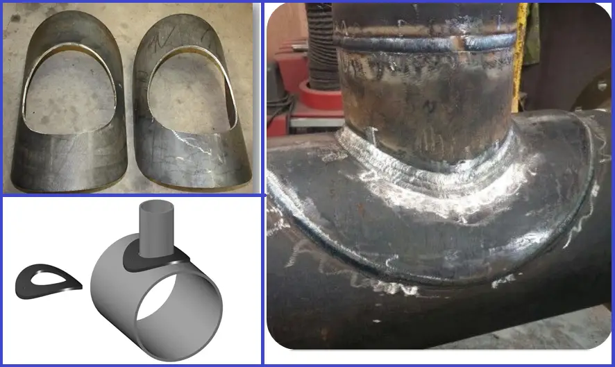
Fig. 1: Typical Reinforcing PADs
Design Features of RF PAD
The thickness of the RF pad should match the pressure design thickness required for the branch, based on the stress generated at the piping branch connection.
Normally, the maximum thickness that is used in engineering companies as reinforcing pad thickness is 1.5 times the parent pipe thickness. Standard practice is to use the same thickness as the parent pipe.
The reinforcement material must be compatible with the parent and branch pipe material. Normally the same material as the header pipe is used for the RF pad.
Clause 328.5.4.g of ASME B31.3 mentions that Reinforcing pads and saddles shall have a good fit with the parts to which they are attached.
Proper design and size are essential for effective stress distribution and protection. Engineers should carefully consider the dimensions, thickness, and reinforcement pattern to match the specific application.
A vent hole shall be provided at the side (not at the crotch) of any pad or saddle to reveal leakage in the weld between the branch and run and to allow venting during welding and heat treatment. Normally two vent holes are provided, which must be sealed with mastic or silicone gel to restrict the water flow inside the RF Pad. Vent holes are also known as weep holes or telltale holes. The normal size of the weep hole is 6 mm. If the reinforcement pad is made of multiple pipe cuts, then a vent hole should be provided in each cut piece.
A pad or saddle may be made in more than one piece if joints between pieces have strength equivalent to pad or saddle parent metal, and if each piece has a vent hole.
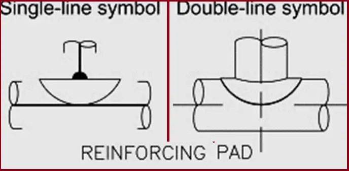
Repad Symbol | Reinforcing Pad symbol in Drawings
Fig. 2 shows the normal RF Pad symbol that is used in piping drawings.
Fig. 2: Reinforcing PAD symbol
The reinforcing pad is a ring cut from a steel plate that has a hole in the center equal to the outside diameter of the branch connection. It is slipped onto the branch pipe before the branch pipe is welded to the header. Once the branch has been welded to the header, the reinforcing pad is slid down the branch to cover the weld connection. The reinforcing pad is then welded to both the branch and the header.
The use of RePADs in piping or equipment nozzles offers several benefits, including
Enhanced Durability: The primary advantage of RF pads is their ability to enhance the durability of piping systems and equipment nozzles. Their robust design helps resist high temperatures, pressures, and corrosive environments.
Cost-Effectiveness: While the initial investment in RF pads may be higher, they can lead to significant savings in the long run by reducing maintenance costs and extending the lifespan of equipment.
Versatility: RF pads are suitable for a wide range of applications and industries, including chemical processing, oil and gas, and power generation. They can be customized to meet specific requirements based on the operating conditions.
Reduced Vibration and Noise: RF pads can help dampen vibrations and reduce noise, contributing to a quieter and more stable operation.
Differences Between Wear Pad and Reinforcement PAD
Wear pad in piping is one additional term that might sound confusing and often seems the same as reinforcement pad. However, the main application of both wear pads and RF pads is quite different. Wear pads are mainly used to protect against wear, erosion, tear, and abrasion, whereas RePADs are more about structural integrity. The following table outlines the key differences between wear pads and reinforcement pads in the context of piping applications:
Aspect
Wear Pad
Reinforcement Pad
Primary Purpose
Wear Pads protect against abrasion and erosion caused by the movement or flow of materials.
RF Pads provide structural support to distribute stress and prevent damage to the piping or equipment.
Function
A wear pad shields the surface from wear and tear, extending the life of the underlying pipe or equipment.
A reinforcement pad distributes mechanical loads and stresses to prevent localized failures and enhance structural integrity.
Application
Commonly used in areas where high friction or abrasive materials are present, such as piping supports due to thermal movement.
Used in locations requiring reinforcement against mechanical stress, thermal expansion, or pressure, such as nozzle connections and pipe branch connections.
Installation
Wear pads are often attached directly to the surface that is exposed to wear, often with bolts, welding, or adhesive.
RF pads are installed around or near nozzles and supports to distribute loads; may require precise alignment and secure attachment.
Design Focus
Designed to endure abrasion, impact, and erosion.
Designed to handle stress, pressure, strain, and thermal expansion, often with a focus on load distribution.
Wear Pads vs Reinforcement Pads
Part of this article is prepared by Mr. Satish Atmanathan, a senior oil, and gas professional with extensive work experience. For a more detailed explanation of all the above parts and visualization, listen directly to him in the following video:
I am a Mechanical Engineer turned into a Piping Engineer. Currently, I work in a reputed MNC as a Senior Piping Stress Engineer. I am very much passionate about blogging and always tried to do unique things. This website is my first venture into the world of blogging with the aim of connecting with other piping engineers around the world.
12 thoughts on “What is a RePAD, RF Pad, or Reinforcement Pad?”
In low support connection having with pad and reunion pipe mounted over main or run pipe.so mai questions is joining to trunion pipe is with pad or main pipe by having a hole in pad. Please suggest me.
I believe that your article should provide some qualitative guidance on when a RePAD piping joint is a superior solution to a ANSI tee or WELDOLET.
Here in the US, where manual welding is relatively expensive, I have been instructed that the ANSI tee was always the cheapest choice, followed by use of the proper weldolet, …THEN AND ONLY THEN was a RePAD tee permitted by management
Of course, where there were odd branch sizes, availability problems or exotic materials, RePAD was the only solution and was permitted.
I believe that your article would be more complete if you were to address this issue
GRE Design Envelope (Failure envelope) is a 2-dimensional (2D) graphical plot of hoop stress and axial stress that provides safe operating conditions of GRE piping/pipeline system when subjected to...
While performing buried or underground pipeline stress analysis, soil parameters must be entered in Caesar II software to help the software generate the bilinear restraints. The usual parameters that...


? | NFPA Codes and Standards")


Very informative????????
I want to learn from you
In low support connection having with pad and reunion pipe mounted over main or run pipe.so mai questions is joining to trunion pipe is with pad or main pipe by having a hole in pad. Please suggest me.
contact @+91 8447075363
I believe that your article should provide some qualitative guidance on when a RePAD piping joint is a superior solution to a ANSI tee or WELDOLET.
Here in the US, where manual welding is relatively expensive, I have been instructed that the ANSI tee was always the cheapest choice, followed by use of the proper weldolet, …THEN AND ONLY THEN was a RePAD tee permitted by management
Of course, where there were odd branch sizes, availability problems or exotic materials, RePAD was the only solution and was permitted.
I believe that your article would be more complete if you were to address this issue
Best Regards
Why ID cut is required in the pads which are used in trunnion supports
SOMEONE HAS THIS TYPE OF DETAIL FOR BRANCH PIPE TO PIPE SAME DIAMETER WITH REINFORCED PAD?
How to calculate nozzle pad plate diameter
Can you please guide : Why reinforcement pad is to be pneumatically tested? What is the standard based on which pad is pneumatically tested?
Sir, One of my customer require this reinforcing pad , where can I get this material in India ?
Please Suggest
No mention of the required area replacement calculations to determine the requirements for a pad in the first place?
Dear Sir ;
How to calculate the reinforcement pad diameter for equale tee branch
Thanks in advance