
Venturi meters are instruments for fluid flow measurement. It has a converging section that gives an increase in the flow velocity with a corresponding drop in pressure from which the flow rate can be calculated. The reduction in the fluid pressure that occurs when a fluid moves through a constricted passage is known as the Venturi effect. Venturi meters are widely used wherever there is a need for fluid flow measurement, specifically in water, chemical, and oil industries. Depending on the application and size requirements, industrial venturi meters are constructed in various forms. These versatile instruments are known for longevity, long performance, and reliability. In this article, we will discuss about the following:
- Definition of Venturimeter
- Venturimeter Diagram and Parts
- Working Principle of Venturi meter
- Venturimeter Formulas
- Co-efficient of Discharge for Venturimeters
- Venturimeter Types
- Applications, Advantages, and Disadvantages of Venturimeters
- Difference between Venturimeter and Orificemeter, and
- Many more.
What is a Venturimeter? Venturimeter Definition
Venturimeter is a type of flowmeter that works on the principle of Bernoulli’s Equation. This device is widely used in the water, chemical, pharmaceutical, and oil & gas industries to measure the flow rates of fluids inside a pipe. The pipe cross-sectional area is reduced to create a pressure difference which is measured with a manometer to determine the rate of fluid flow. So, the venturi meter is a differential head type flowmeter that converts pressure energy into kinetic energy.
The principle of the Venturimeter was demonstrated by Giovanni Batista Venturi (Hence the name Venturimeter), But it was first used in practical metering applications by Clemens Herschel. In this article, we will explore the parts, working principles, equations, and applications of the Venturimeter.
Venturimeter Diagram and Parts
A venturimeter consists of four parts:
- Cylindrical Inlet Section
- Conical convergent Section
- Cylindrical throat and
- Conical divergent outlet
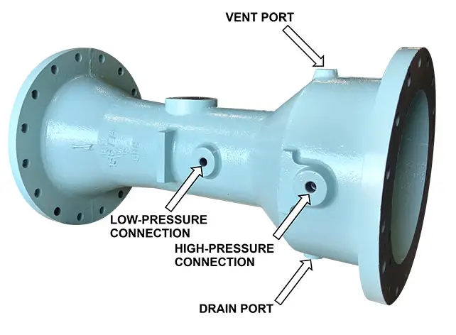
Fig. 1 below shows a typical venturimeter diagram with its parts.
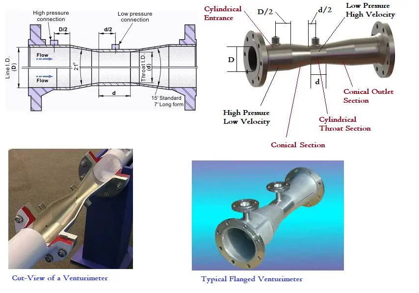
There are two tappings on the venturi meter for pressure measurement; the upstream pressure tapping is located at a distance of one-half of pipe diameter (D/2) upstream of the convergent entry, while the downstream pressure tapping is located in the throat (d/2) as shown in Fig. 1.
- Cylindrical Entrance Section: Venturimeter entrance is a straight cylindrical section with a length equal to 5 to 8 times the pipe diameter.
- Convergence Conical Section: In this section, the venturi meter tube diameter gradually decreases. The conical angle is normally 210 ± 20. While the liquid flows inside the venturimeter, the velocity of fluid increases at the expense of a decrease in pressure.
- Cylindrical Throat: Throat consists of the minimum venturemeter diameter. In the throat section, the velocity is maximum and pressure is minimum. Normally, throat diameter = 1/3 to 1/4th of inlet pipe diameter.
- Diverging Conical section: At this section of venturimeter, the tube diameter gradually increases. So, the pressure is built up again to the original inlet pressure. The cone angle is 5-70. British Standard BS-1042 specifies two conical angles, 5–70 and 14–150 for the outlet cone.
Materials for Venturimeter
Small-size venturimeter are made of brass, glass, or bronze and large venturimeters are made of cast iron, steel, or stainless steel.
Working Principle of a Venturimeter | How Does a Venturi Meter Work?
When a fluid flows through a venturimeter, it accelerates in the convergent section and then decelerates in the divergent section. The pressure difference between an upstream section and the throat is measured by a manometer. Using that differential pressure, applying Bernoulli’s Equation and Contininuity Equitation the volumetric flow rate can be estimated. In the next section, the equations of venturimeter to find the discharge value are discussed.
Venturimeter Equations | Formulas for Venturi Meters
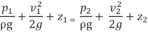
Bernoulli’s principle states the relation between pressure (P), kinetic energy, and gravitational potential energy of a fluid inside a pipe. The mathematical formula of Bernoulli’s equation is given as:
Where,
- p= pressure inside the pipe
- ρ =density of the fluid
- g =gravitational constant
- v = velocity
- z=elevation or head
- a = cross-sectional area of the pipe
- d= diameter of the pipe
Suffixes 1 and 2 are used to denote two different areas; 1 denotes the cylindrical inlet section and 2 denotes the throat section.
Now as the pipe is horizontal; there is no difference in the elevation of the pipe centerline; So, z1=z2. Re-arranging the above equation we get the following:
(p1-p2)/ρg = (v22-v12)/2g
(p1 – p2)/ ρg is the difference of pressure heads in sections 1 and 2 which is equal to h that can be measured in the differential manometer. So the above equation becomes
h=(v22-v12)/2g……….eqn. 1
Now applying continuity equations between the same sections 1 and 2, we get
a1v1=a2v2 or v1=(a2v2)/a1
Putting this value of v1 in eqn. 1 and solving we get,
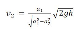
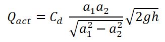
So, the rate of flow through the throat (Q) can be calculated as Q=a2v2; Substituting the above value of v2 we get,
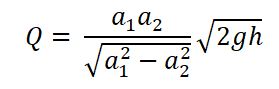
This Q represents the theoretical discharge of Venturi Meter in ideal conditions. But in actual practice, there will always be some frictional loss. Hence, the actual discharge will always be less than the theoretical discharge. So, to calculate the actual discharge, the above Q value is multiplied by Cd, called the Coefficient of discharge of venturimeter. So the actual flow rate through the throat of the venturimeter will be given by the following equation.
Coefficient of Discharge of Venturimeter (Cd)
The coefficient of discharge for Venturimeter, Cd is defined as the ratio of the actual flow rate through the venturi meter tube to the theoretical flow rate. So the venturi meter discharge coefficient is given by:
Cd=Qact/Q
As Qactual will always be less than Qtheoretical due to frictional losses, the value of Cd is always less than 1.0.
The typical range of the discharge coefficient of a Venturi meter is 0.95-0.99 but this can be increased by proper machining of the convergent section. The value of venturimeter discharge coefficient differs from one flowmeter to the other depending on the venturimeter geometry and the Reynolds number.
ISO-5167 code provides the values of venturimeter discharge coefficients. For accurate flow measurement, normally straight length requirement upstream and downstream of venturimeter is specified.
Types of Venturimeters
Normally three types of venturimeters are available:
- Horizontal Venturimeter: This type of venturimeter has the highest kinetic energy and the lowest potential energy.
- Vertical Venturimeter: This type has the maximum potential energy and the minimum kinetic energy.
- Inclined Venturimeter: Both potential and kinetic energy are in between the above two types mentioned.
Applications of Venturimeter | Venturimeter Uses
Venturimeters find wide application in fluid industries. The major application of venturimeters include
- Used in Engine Carburetors (Automobile Sector) to measure airflow
- Used in process industries (Process and Power Piping Industries) to measure and control process flow.
- In the medical industry, blood flow in the arteries is measured by venturimeters.
- Measures the fluid flow inside pipelines (Oil & Gas Industries)
Broadly the use of venturimeters are versatile and widely used in the following industries:
- Water treatment plant
- Chemical processing
- HVAC systems
- Power Generation systems
- Oil and gas industry
Advantages and Disadvantages of Venturimeter
Advantages of Venturimeter:
- They provide accurate results.
- The accuracy of venturimeter is not dependent on temperature and pressure inside the pipe.
- No moving part.
- Very low energy loss.
- Wide applicability for Water, suspended solids, gases, slurries, chemicals, dirty liquids, etc.
- High discharge coefficient and very low-pressure drop.
- Venturimeters can be installed in a horizontal, inclined, or vertical direction.
- Very little chance of being clogged.
- The pressure recovery of venturimeter is very high. The discharge pressure is almost near to inlet pressure.
Disadvantages of Venturimeter:
- Venturi meters are large in size; so difficult to install where there is space constraint.
- Expensive as compared to other types of flowmeters
- Limited range of flow measurement
- Not suitable for very small diameter pipes.
Codes and Standards for Venturi Meter
The codes and standards that provide guidelines related to venturi meters are
- ISO 5167
- ISO 9300
- AWWA M33
- ISO TR 15377
- BS 1042
- ASME MFC-8M
- ASTM D2458
- AGA 9
Installation of a Venturi Meter
Proper installation of a venturi meter is the key to the ideal operation. So, the installation of venturi meters must be performed following manufacturer guidelines. Normally, the following guidelines to be followed while installing a venturi meter in a piping or pipeline system:
- The flow direction arrow in the venturi meter should be checked and installed to agree with the direction of the flow.
- Flanges at the venturi meter ends should be properly aligned with the piping flanges.
- Pipe Support should not be placed on venturi meters.
- Bolts should not be over-torqued.
- Installation tolerances should be within industry standards.
- Pressure taps should be oriented horizontally for liquid service applications.
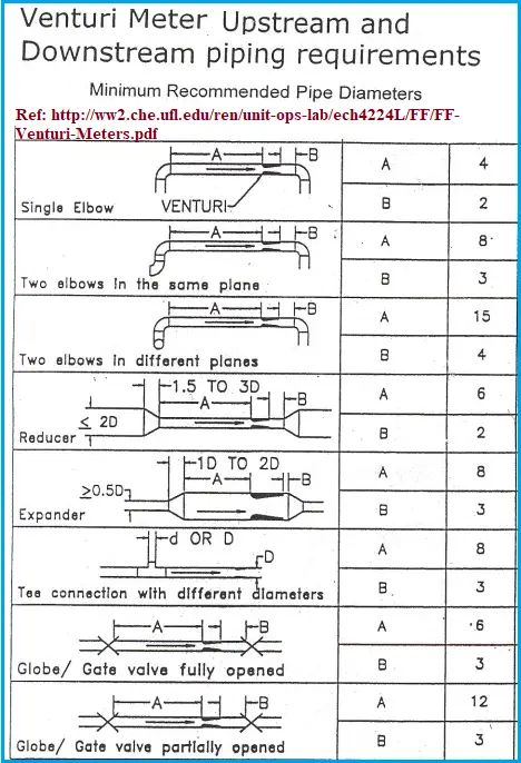
Venturi meter Upstream and Downstream Pipe Straight Leg Requirement
For proper functioning and accurate results, the flow through the venturi meters should stabilize. This calls for minimum straight pipe length requirements upstream and downstream of the venturi meter. Depending on the type of fitting, type of venturi meter, and beta ratio (the throat diameter divided by the inlet diameter) the straight leg requirement varies. The following image (Fig. 2) provides a sample table that provides typical strength leg requirements while installing a venturi meter in a piping system.
Design of Venturimeters
Even though standard classical venturimeter designs need a bit more space, the significant benefit is that their design can easily be modified to fit any requirement. Over the last centuries, venturimeter design has undergone significant changes and two specific designs have contributed in significant impact on Venturi metering; They are:
- Modifies Short form Venturimeters, and
- Insert Venturi meters.
Modifies Short form Venturimeters: Patented by Dezsoe Halmi, these designed forms of venturimeters are highly accurate, have low headloss, and need no upstream/downstream straight length requirements. Modifies Short-form Venturimeters are more suitable for asymmetric flow patterns due to their overall short length.
Insert Venturi Meters: Insert venturimeter design is somewhat similar to the shape of a Classical Venturi but its profile is entirely inside the pipeline. They utilize a static low-pressure throat tap that sense pressure perpendicular to the axis of the flowing line fluid.
Difference between Venturi meter and Orifice meter | Venturimeter vs Orifice Meter
Venturi meters and orifice meters are both types of differential pressure flow meters that are commonly used to measure the flow rate of fluids in pipes. While they are similar in some respects, they differ in several important ways, including their design, performance characteristics, and applications.
Venturi meters are typically designed with a tapered throat section that gradually reduces the cross-sectional area of the pipe. As the fluid flows through the throat, its velocity increases and its pressure decreases, creating a pressure differential between the upstream and downstream sections of the meter. This pressure differential is proportional to the square of the flow rate and can be measured using pressure gauges or transducers.
In contrast, orifice meters use a flat plate or disc with a precisely measured hole in the center to constrict the flow of fluid in the pipe. This creates a pressure drop that is proportional to the square of the flow rate and can be measured in the same way as with a venturi meter.
Here are some key differences between Venturi meters and orifice meters:
Design: A Venturi meter has a gradual taper to the throat section, while an orifice meter has a sharp-edged disc or plate with a hole in the center.
Pressure recovery: The pressure recovery in a Venturi meter is better than in an orifice meter, meaning that the pressure downstream of the meter returns closer to the upstream pressure.
Accuracy: Orifice meters are generally less accurate than Venturi meters, particularly at low flow rates, where the turbulence caused by the sharp-edged orifice plate can create errors.
Applications: Venturi meters are often used for high flow rates and in systems where pressure drop is a concern, while orifice meters are used in a wider range of applications, including lower flow rates and where cost is a concern.
Installation: Venturi meters require longer straight sections of pipe upstream and downstream of the meter to achieve accurate readings, while orifice meters can often be installed with less straight pipe.
Overall, the choice between a Venturi meter and an orifice meter will depend on the specific requirements of the application, including flow rate, accuracy, pressure drop, and cost.
The major differences between a venturimeter and an orifice meter can be tabulated as follows:
| Venturi Meter | Orifice Meter |
| Venturi meter comes with complex designs. | Orifice meters are easy to fabricate |
| Venturimeters have a large space requirement | Orifice meters, on the other hand, need relatively lower space. |
| In venturimeter, the Energy Loss is less. | Orifice meters have comparatively more energy loss. |
| Venturimeters are quite expensive. | Orifice meters are comparatively cheaper. |
| High discharge coefficient. | Low coefficient of discharge. |
| Venturimeters provide High-Pressure Recovery. | Pressure Recovery in the Orifice meter is relatively less. |
FAQ on Venturimeters
1. What is a venturi meter used for?
A venturi meter is used to measure the flow rate of fluids in a pipe. It is widely employed in various industries, including water treatment, chemical processing, oil and gas, and HVAC systems. By measuring the pressure difference between the inlet and the throat of the venturimeter, it provides accurate flow measurements, which are essential for process control and optimization.
2. How does a Venturi device work?
A Venturi device works on the principle of the Venturi effect, which states that as a fluid flows through a constricted section of a pipe, its velocity increases, and its pressure decreases. The venturimeter has a convergent section that narrows into a throat and then diverges. Pressure taps are located before and at the throat. The difference in pressure between these points is used to calculate the flow rate of the fluid using Bernoulli’s equation.
3. What is the working principle of the venturi effect?
The Venturi effect is based on Bernoulli’s principle, which states that an increase in the velocity of a fluid results in a decrease in its pressure. As fluid flows through the constricted throat of the venturimeter, its velocity increases, causing a drop in pressure. This pressure drop is measured and used to determine the flow rate of the fluid.
4. Why is it called a venturi?
The device is named after Giovanni Battista Venturi, an Italian physicist who first described the principle in the 18th century. Venturi’s research on the effects of fluid flow through constricted sections of pipes led to the development of this flow measurement device.
5. What is the ratio of venturi meter?
The ratio of a venturi meter typically refers to the area ratio between the pipe’s diameter at the inlet and the throat. This ratio is crucial for determining the meter’s accuracy and performance.
6. What is the ISO standard for venturi meter?
The ISO standard for venturi meters is ISO 5167. This standard specifies the requirements for the design, installation, and testing of venturi meters used for measuring the flow of liquids, gases, and steam. It ensures that the venturi meters meet international standards for accuracy and reliability.
7. What size is a Venturi pipe?
The size of a Venturi pipe varies depending on the specific application and flow rates required. Venturi meters can be designed for a wide range of pipe sizes, from small laboratory setups with diameters of a few millimeters to large industrial pipes with diameters exceeding several meters. The size is typically chosen based on the fluid flow rate and the accuracy requirements.
8. What is the coefficient of Venturi?
The coefficient of a venturi meter, often referred to as the discharge coefficient (Cd), accounts for losses and deviations from the ideal flow. It is a dimensionless number that varies with the design of the venturi meter and the characteristics of the fluid. It is used to adjust the theoretical calculations to match the actual flow measurements. The value of Cd is usually determined through calibration and testing.
9. What is the advantage of venturimeters?
Venturi meters offer several advantages:
- High Accuracy: They provide accurate flow measurements with minimal pressure loss.
- Durability: They have no moving parts, which reduces maintenance and wear.
- Wide Range: They are suitable for measuring a broad range of flow rates.
- Versatility: They can measure various fluids, including liquids, gases, and slurries.
- Minimal Pressure Loss: Compared to other flow measurement devices, venturi meters exhibit relatively low-pressure drops, which is advantageous for maintaining system efficiency.
Video Tutorial on Venturimeters
The above contents are explained in the following video tutorial on Venturimeters titled “What is a Venturimeter?”
helpful 😀 thank you sir
Congratulations Anup, very helpful and educational article on venturi meters!
Thank you sir
A Venturimeter of 2.5 cm diameter and 1.5 cm diameter at throat will give good/acceptable results or not? What should the minimum recommended diameter of venturimeter for good/acceptable results? What could be the maximum error in venturimeter readings, if the diameter is small (example 2.5 cm or less)?
Superb.Got what was looking for.Excellent explanation Sir😊
Very much informative. Thanks a lot
How many taps is possible in a Venturi – is possible 3 nos. case the compressor, one for anti-surge, one for performance and other for load sharing, the idea is not installing two (2) venturis in serie