
A large number of Piping failures in Very Large Diameter Water pump piping systems forced client companies to consider water pump station piping as a critical system. Pump station piping is normally very compact due to space constraints and the possibility of including any inherent piping flexibility by adding elbows is limited. At the same time, the Very Large size (diameter) of the suction and discharge piping makes the system highly rigid. In this scenario, piping stress engineers are left with only two options to qualify the pump suction and discharge nozzles.
- Using Expansion Joint
- Using Flexible Sleeve Couplings
Both methods provide flexibility in the system and are highly effective in absorbing thermal movements in the system.
But The main drawback with Expansion Joints is their high cost with respect to design life and the requirement of additional standby expansion joints. So in recent times, design consultancies are using Flexible Sleeve Couplings to a large extent. Compared to the expansion joints, flexible sleeve couplings are economic for their design life.
In this article, We will describe the stress analysis of a Water Pump Station Piping employing Flexible Sleeve Couplings. Hexagon PPM software Caesar II is used for analysis.
What is a Flexible Sleeve Coupling?
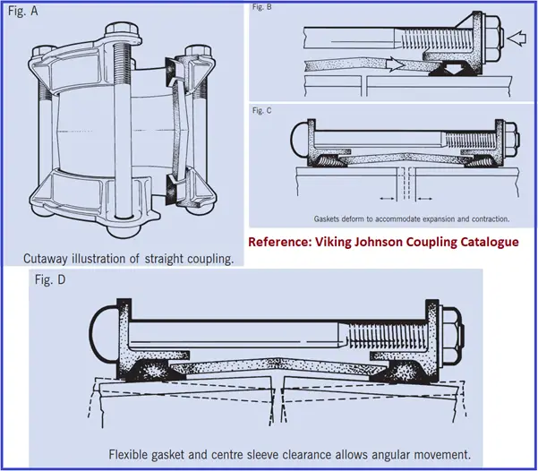
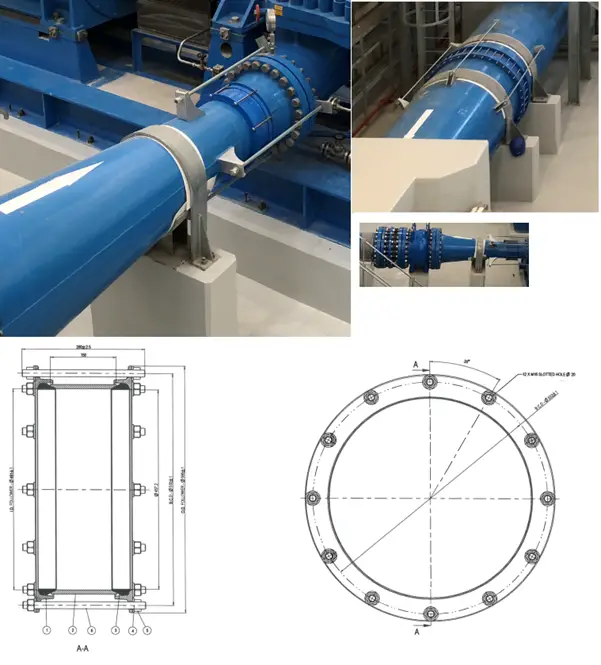
The Flexible Sleeve coupling (Fig. A) comprises a center sleeve located between two end rings. The sleeve and end rings are separated by wedge-shaped elastomeric gaskets. The tightening of the head bolts draws the end rings together, thus compressing the gaskets between the end rings and the center sleeve. As the gasket is forced onto the pipe surface, an effective leak-proof seal (Fig. B) is achieved. Such flexible couplings are capable of absorbing thermal expansion and contraction removing the need for expansion bellows (Fig. C).
Additionally, it has the ability to accommodate enough angular deflection to allow for pipeline movement or ground settlement, or to provide for long radius curves without the necessity of incorporating purpose-made bends (Fig. D).
Stress Analysis System Definition
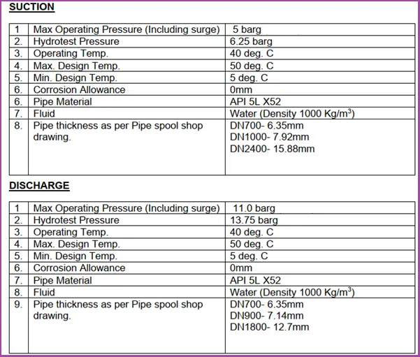
The Stress Analysis system consists of a Water Pump station consisting of four pumps and two future tie-ins. The line parameters are given below for reference:
Data required from the Vendor
The following data need to be collected from the Vendor
- Flange and Valve weights.
- SIF values at branch connections.
- Pump GA drawing with Nozzle Allowable loads.
Modeling the Stress system
Refer to Fig. 3 to visualize the complete system.
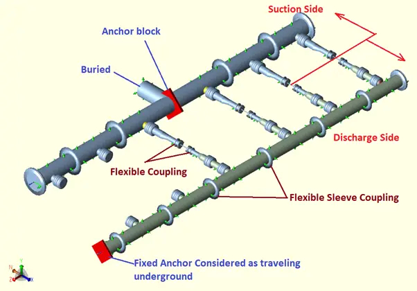
The Governing code for the system is ASME B31.4. Pipe elements are modeled in the same conventional way. A fixed anchor is considered at the interconnection of buried and aboveground parts for the discharge header. The pump is modeled as rigid with zero weight.
The piping pressure thrust force is calculated as Pressure X Internal Cross-Sectional Area and added in direction changes.
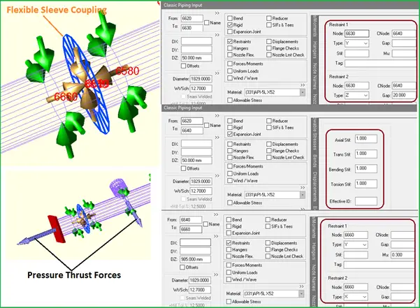
Modeling the Flexible Sleeve Coupling in Caesar II
- In Caesar II, the sleeve coupling (Fig. 4) is modeled as an expansion joint with very low stiffness values.
- Effective ID is left blank as the sleeve coupling is used with a harness (tie rod) so no need to calculate coupling thrust force.
- Axially a displacement of 20 mm is considered as the coupling can absorb a displacement up to 20 mm (Need to be checked with the vendor on a case-to-case basis).
- An all-around guide is provided on both sides of the sleeve coupling at the nearest possible distance from the coupling.
- Refer to Fig. 4 for more details.
- The Flexible sleeve coupling (Fig. 5) is modeled by elements 6620-6630; 6620-6640; At nodes 6580 and 6660 all-around guides are provided to avoid bending of the coupling. At node 6630 a 20 mm displacement is provided for axial movement.
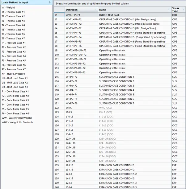
Load Cases for Analysis
Load cases are prepared considering 3 pumps as operating and one pump as stand-by. Refer to Fig. 6 for the analysis load cases. Seismic loads are considered to act in any single direction.
Few more Useful Resources for You..
Stress Analysis Basics
Stress Analysis using Caesar II
Stress Analysis using Start-Prof
Piping Design and Layout basics
Piping Materials Basics
Dear, Very interesting information, I wanted to make the following inquiries:
1.-Why does ASMA B31.3 not apply?
2.-Are there or can Coupling for Class 600 be manufactured?
3.-What are the restrictions of linear and angular displacements, for different diameters?
4.-What should you check in the Caesar II Model, when modeling Coupling?
5.-What maximum temperature can be used?
6.-What vendor is there in the market?
Thank you in advance for the information and clarifications.
regards
Pedro Salgado
Hi Sir,
Very Useful information.
I have some Doubts related to pump piping,
1. In which case we have apply pressure thrust as a separate load in Caesar II?
2. Is it Okey to model sleeves by defining Cnod at the end of one pipe element and connect it to the next element by Cnod with 20 mm gap axially and by restraining other directions(ie without rigid element and Exp. Joint).
2. While modelling the flexible connector (Rubber Joints) is it require to give effective diameter , Is the thrust force associated with normal flexible connectors?