
Plant layout design means efficiently placing equipment, piping, instrumentation, and other manufacturing supports and facilities with proper planning during the design stage to create the most effective plant layout. It is directly related to project costs as well. The most efficient plant layout has less overall project cost and the most utilization of all resources.
The main objective of efficient plant layout design is to design and construct the plant in an economic fashion that meets all the process requirements and client specifications while operating in a safe reliable manner. This article provides the basic considerations for the development of plant layout. For more details on any of the listed points, you can refer to any standard piping books.
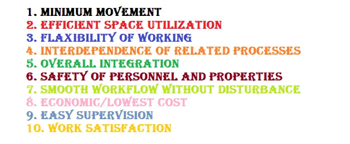
Principles of Plant Layout
While developing plant layouts following 10 principles are kept in mind.
Plant Layout Design rules for Site Selection
- Location
- Area Allocation
- Transport Facilities
- Manpower availability
- Industrial Infrastructure
- Community Infrastructure
- Availability of Water
- Availability of Power
- Effluent Disposal
- Availability of Industrial Gas
- Site Size
- Ecology
- Pollution
What is Plot Plan & its requirement?
The plot plan is the master plan locating each unit/facility within the plot boundary for a process industry such as
- Refinery
- Chemical /Agro Chemical / Petro Chemical / Organic Chemical / Inorganic Chemical
- Fertilizer
- Pharmaceutical
- Metallurgical
- Power Generation
It is used to locate the unit/facility.
The following main aspects shall be considered during the development of the layout.
- Process requirement
- The economy of piping material and cables
- Erection & Construction requirements
- Safety requirements.
- Operation and Maintenance requirements.
- Grouping of similar equipment for the convenience of maintenance & safety wherever possible.
Data to be collected before starting the process of plant layout development
Data from the Civil Department
- Plane table survey map.
- Contour survey map.
- Soil bearing capacity.
- Nature of Soil
- Rail/Road Access.
Data required from Electrical Team
- Location of Electric Supply Point.
- Supply voltage levels.
- Fault Levels.
- Voltage Levels required within the unit.
- Proposed distribution scheme.
Non-Plant Facilities
- Administrative Block
- Canteen
- Workshop
- R&D, QC Lab, and Pilot Plant
- GateHouse/Time office
- Security Arrangements
- Vehicle Parking
- Medical Centre
- Ware House
- Covered Area
- Open Area
- Solid Warehouse
- Liquid Warehouse
- Steel / Scrap Yard
- Fire Station
- Weigh Bridge
- Staff Colony
Meteorological Data
- Minimum, Maximum, and Normal Temperature during the year
- Rainfall
- Intensity and Direction of the wind (wind rose)
- Seismic zone
- Wet and Dry Bulb temperatures
- Relative humidity
- Flood level
Process Data
- Size/Capacity of the processing unit
- Knowledge of the type of plant
- The sequence of process flow
- Hazardous nature of the plant
- The Overall operating philosophy
- Fully Automatic
- Partially Automatic
- Manual
- Batch/Continuous
- Raw material receipt and product dispatch philosophy
- Storage Philosophy
- Effluent plant capacity and discharge points, incineration requirements, etc.
- Type of Hazard
- No of flares
Data on Utilities
- Source and/or supply point of raw water
- Quality of Water available
- Water Consumption for the process
- The requirement of different types of utilities such as Steam, Air, Nitrogen, DM water, Firewater, Brine, etc.
- Capacities and Grouping philosophy.
Statutory Requirements and process plant layout
- State Industrial Development Corporation (SIDC)
- Central / State Environmental Pollution Control Boards (PCBs)
- Factory Inspectorate
- State Electricity Boards (SEB)
- Chief Controller of Explosives (CCOE)
- Static and Mobile Pressure Vessel Rules (SMPV)
- Tariff Advisory Committee (TAC)
- National Fire Protection Association (NFPA)
- Aviation Laws
- Chief Inspector of Boilers (CIB)
- Oil Industry Safety Directorate (OISD)
- Food and Drug Administration (FDA)
- Ministry of Environment and Forest (MoEF)
Expansion Philosophy during plant layout development
- Within the unit
- Additional Units
- Near future expansion
- Far future expansion
Considerations during plant layout
- Normally Construction is permitted on a maximum of 50% of the plot area with a total built-up area equal to the area of the plot (i.e. F.S.I. = 1 (Depending upon the regulation governing the area and the type of industry))
- The area reserved for tree plantation shall be 1/3 of the area occupied.
- Water storage capacity – 24 hr. minimum.
- Domestic water – 100 liters per person per day
- Water requirement for Boiler – Steam rating x Working factor
- Cooling tower – 11/4 % of capacity as drift and blowdown losses
- Washing – 10-15 liters per day per sq. ft. of the floor area of the plant
- Gardening – 5 liters per day per sq. ft. of garden area
- Parking space – 10% of the plot area
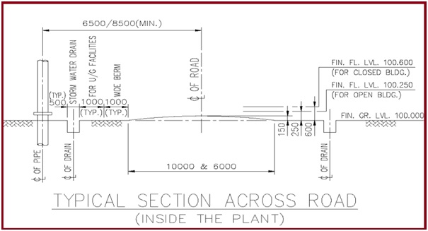
Roads & Paving considerations in Plant Layout
- Roads in the plant shall be planned for the effective movement of trucks, cranes & emergency vehicles, etc. Road width (Blacktop) shall be generally as follows unless specially requested.
- Main plant road & roads connecting to Plant boundaries, roads for fire fighting access are 6 meters wide (Min)
- Secondary roads 4 meters wide (Min)
- The turning radius of the road shall be adequate for the mobile equipment & shall clear of any obstruction. The minimum turning radius is to be the same as the length of the vehicle.
- The finish of the road i.e. graded or blacktop shall be decided in the beginning while developing a plot layout.
- Paving should be provided around the equipment where spillage is likely to occur. For example Pumps or machinery, below furnaces or fired heaters, compressors, etc.
- Also paving should be provided below the Air fin cooler those are located at grade.
- Area handling acids, alkalis, or toxic material shall be paved and bunded. Proper surface treatment shall be provided for paving to meet the service requirements.
The below sketch (Fig. 1) shows the minimum distance required between the road and the facility. This distance shall be reviewed on a case-to-case basis for the project.
Elevations Requirement
- Below data for the elevations should be generally followed.
- Underside the base plate of Structural steel: Min150 mm. above HP of finished grade/paving.
- Stair or ladder pads: Minimum 75 mm. above HP of finished grade/paving.
- Top of Pedestal of Vessel & Tower: Min300 mm. above HP of finished grade/paving.
- Top of Pump pedestal: Minimum 200 mm. above HP of finished grade/paving.
Insulation & Fire Proofing considerations in plant layout
- Fireproofing requirements for pipe racks, vessel supports, and process structure should be considered as these reduce the clearances with access, pipework, instrument & electrical equipment.
- Proper insulation thickness should be considered for pipework & equipment clearances.
Equipment Layout and locations
- Pumps: Locate pumps close to the suction source considering NPSH requirements. Pumps & driver axis should be located perpendicular to the pipe rack or other equipment to minimize fire exposure in case of pump seal failure.
- Gas compressor or Expanders: Gas compressors should be located downwind of the fired heaters, flare, or any open flame equipment. They may be grouped together for maintenance & operations (Common EOT / drop-down area, the single sunshade can be made)
- Plant Air & Instrument air compressors: Plant air & instrument air is vital to the service of the plant. These units should be located near the control room & shall be kept in a safe area sufficiently away from the HAC of equipment.
- Heat Exchangers: Heat exchangers are generally placed on grade unless otherwise due to process or technical reasons. (Platform for vertical heat exchangers, Tube bundle removal area, access to mobile crane or monorail with hoist shall be considered)
- Air cooler: The air cooler is located in such a way as to allow access to mobile lifting equipment. Preferably air cooler is located in the main equipment row in accordance with process requirements.
- Cooling Towers: Cooling towers shall be located away from the process equipment & downwind of the process equipment, substation, and main pipe rack.
- Offsite Tanks: Storage tanks (Grouped and shall be surrounded by a dike wall, Primary/secondary roads for adequate firefighting accessibility, Lower elevations than the other occupancies and downwind flares, furnace heaters). Emergency shutdown valve, pumps, manifold & transfer piping shall be outside the dike area.
Considerations for Pipe ways / Pipe racks
- Pipe ways or pipe racks should be overhead in-process main unit and at grade in off-site.
- Width is determined based on present need + 10% at outset of the job + 15% for future requirements or as specified by the client.
- The requirement of expansion bays, anchor bays & bracing shall be checked with the stress / structural engineer at the beginning of the pipe rack layout.
Relief valve and Flare systems
- A closed relief valve system
- Self-draining
- No pocket to avoid condensation & backpressure.
- Flare shall be located upwind process unit & storage.
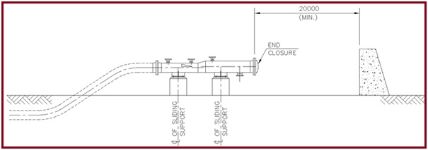
Clearance at Pig Receiver
- The area at the end closure of the Receiver shall be kept free to avoid any incident.
- Provide a concrete wall a minimum of 20 meters away (Fig. 2) from the end closure if the area needs to be utilized for any equipment.
Personal protection Considerations
- Eyewash and emergency showers shall be provided in an area where operators are subject to hazardous sprays or spills.
- Breathing air stations in the facilities handling extremely toxic gases/fluids.
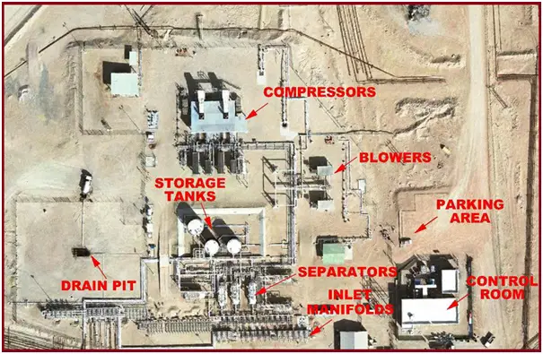
Fig. 3 shows a typical plant layout.
What is a Hazard Classification?
- Hazardous area classification is the risk locating plan for each unit/facility within the plot boundary for the process industry.
- The Plot plan will be used by indicating the boundaries of the risk area.
- HAC drawings are generally used by operators while issuing work permits.
HAC Standard
- HAZARDOUS AREA: An area in which an explosive gas atmosphere is present, or maybe expected to be present, in quantities such as to require special precautions for the construction, installation, and use of apparatus.
- NON-HAZARDOUS AREA: An area in which an explosive gas atmosphere is not expected to be present, in quantities such as to require special precautions for the construction, installation, and use of apparatus.
Process Requirements
- Proper interconnection between equipment to achieve intended process parameters.
- Normally equipment is arranged in the process fluid flow sequence. Requirement like gravity flow (Equipment Drain piping), Thermosyphon system should be considered, and Limitation of pressure & temperature (process parameters) to be considered
- The requirement of upstream and downstream pipe lengths for instruments.
- Hazardous & Toxic fluids shall be identified. (H2S, Cyanide, Methanol, etc.)
- Equipment handling hazardous fluids like flares and direct-fired equipment containing open flame shall be located separately.
- Similarly, equipment handling toxic material shall be located with restricted access or in accordance with local statutory regulations.
Economic Considerations
- Equipment shall be located without affecting the process requirement for maximum economy of pipework & supporting steel with consistent standard clearances, construction, and maintenance & safety requirements.
- Runs of exotic material & large bore piping shall be minimized.
- Optimum utilization of the structure to be ensured.
Erection & Construction
- Road access for the erection of pipe support/pipes and equipment.
- The clear area for the crane to erect equipment on the location from the trucks.
- The minimum one side of the pipe rack shall be kept clear.
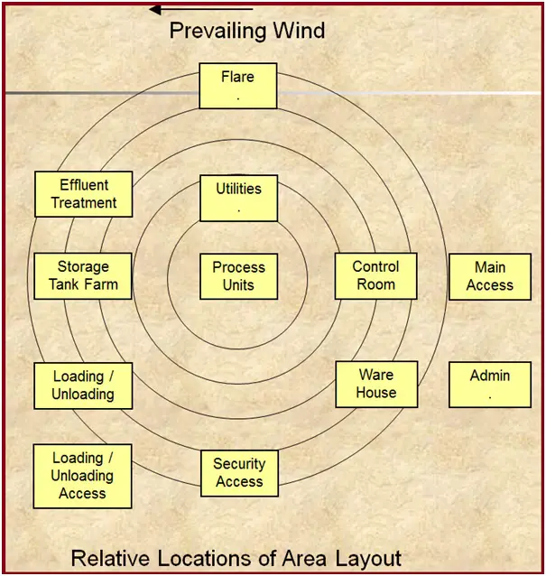
Fig. 4 shows relative locations for area Layout.
Perfect Points… Gantry and Parking truck and cars..
Can you pls clear my space requirement funda regarding piping, maintance / oparation & Erection.. For plot plan layout development..
please provide me pdf on piping layout and ETP & STP layout
This blog on Plant Layout Design Rules and Piping Layout Rules is accessible in PDF format and is a great resource for professionals looking to ensure accuracy and compliance with industry standards in their projects.
Can u provide detailed explanation on deciding the upwind and downwind wind direction related to plot plan