What is an Elevated Flare System?
The elevated flare system consists of a flare header, a knock-out drum, and a flare stack. The waste gas and condensate are collected from the whole plant through the flare header and then the condensate is separated in the knock-out drum finally, the gas is burnt in a stack at a high elevation. As the combustion of gases (toxic) is done at the flare tip at a high elevation, the complete system is called Elevated Flare System.
Purpose of flare system
The primary function of a flare system is to use combustion to convert flammable, toxic, or corrosive vapors to less objectionable compounds like CO2.
Why not cold vent instead of flaring?
Methane is roughly 30 times more potent as a heat-trapping gas than CO2. Hence cold venting of HC gases is not allowed as per pollution control board directives.
Design standards for Flare System
- API 521: Pressure-relieving and Depressuring systems
- DEP 80.45.10.10: Flare and vent systems (amendments to API 521)
- API537: Flare details for refinery and petrochemical service
- DEP 80.45.11.12: Flare details (amendments to API 537)
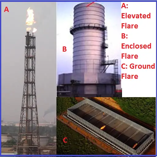
Types of Flares (Fig. 1)
- Elevated flares: Commonly used in the oil and gas industry and the most economical.
- Enclosed flares: Used in plants where a visible flame is not acceptable. Also used for offshore facilities.
- Advantages: Low noise and radiation levels;
- Disadvantage: Poor dispersion of gases during flameout condition (flare needs to be tripped on gas detection)
- Ground flares: Used for liquid or two-phase relief flaring.
- Advantages: Low radiation, low noise;
- Disadvantage: accumulation of vapor cloud, high initial cost.
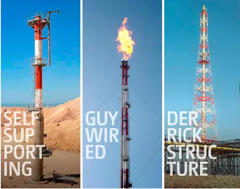
Types of Elevated Flares (Fig. 2):
Self-supported stacks
Simplest and most economical design; Stack height up to 100 ft overall height; As the flare height and/or wind loading increases, the diameter and wall thickness required become very large and expensive.
Guy wire-supported stacks
Most economical design in the 100- to 350-ft height range. Normally, sets of 3 wires are anchored 120 degrees apart at various elevations.
Derrick supported stacks
The most feasible design for stack heights above 350 ft. Derrick supports can be fabricated from pipe (most common), angle iron, solid rods, or a combination of these materials. They sometimes are chosen over guy-wire-supported stacks when a limited footprint is desired.
Non-Assisted / Assisted Flares:
- Non-assisted flares are the flares that do not use any assist media and are typically used for hydrocarbon or vapor streams that do not cause smoking (i.e. For clean-burning gases like methane, hydrogen, carbon monoxide, ammonia, hydrogen sulfide) or when smoke is not a consideration.
- The incomplete combustion of heavy HC gases produces Carbon monoxide, which is the main component to create smoke. For flaring heavy gases, a smokeless operation can be achieved by assisting media such as steam, air, or gas which improves the mixing of flare gas with air.
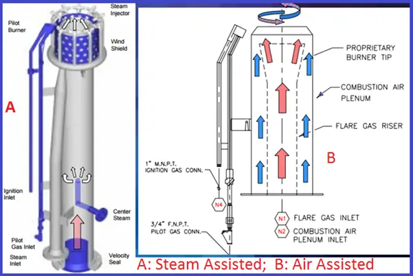
- Steam-assisted flares (Fig. 3) for smokeless operation. Steam increases the momentum of flare gas which enhances fuel-air mixing leading to complete combustion. Also, the water-gas shift reaction converts CO to CO2
CO + H2O ⇌ CO2 + H2
- Air-assisted flares (Fig. 3) are used where smokeless burning is required. It is used when steam is not available or where low-pressure air delivery offers a lower cost. (the only fraction of the requirement of air is mixed with flare gas to promote momentum which effectively entrains additional combustion air from the surrounding).
Flare load estimation (Fig. 4)
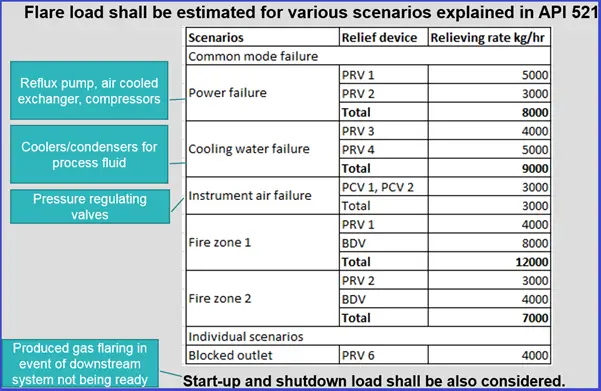
- Fire zone: Wetted areas within a 300 m2 (3200 ft2) plot area shall be considered when a system’s relief loads are calculated.
- Flare gas flow rate: Tip diameter is decided based on the design flow rate.
- Mach number in Stack: 0.5
- Mach number in tip: 0.5 to 0.8 (depends on allowable pressure drop)
- Lower gas velocity (Fig. 5): When the gas flow is so low that the local gas velocity is less than flame velocity, air entrains into the flare tip leading to burning back / flashback. At very low gas velocities, the flame can travel back through the mixture (flashback) into piping and KOD.
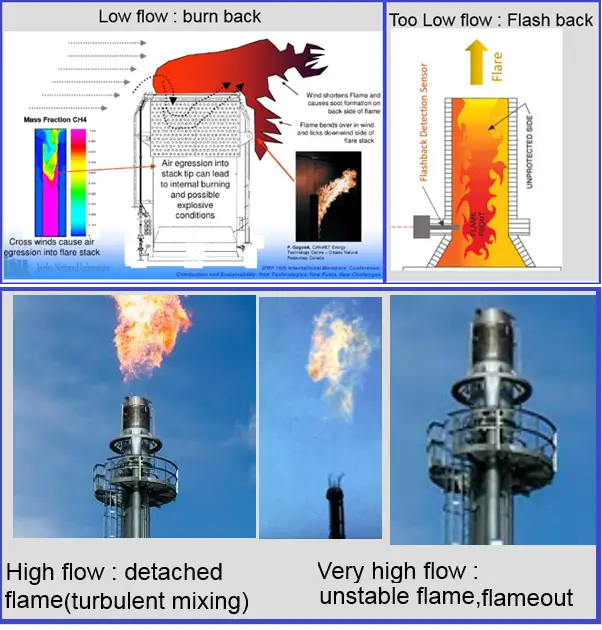
- Higher gas velocity (Fig. 5): When the gas flow is higher than the design capacity, then the local gas velocity becomes higher than the flame velocity leading to detached flame or flameout (higher velocity leads to turbulence, which in turn reduces HC component concentration below LFL)
- Flame velocity: The burning velocity or flame speed is the velocity at which a flame front moves through the unburnt gas/air mixture. This flame speed varies with the air/gas mixture ratio and the chemical makeup of the gas.
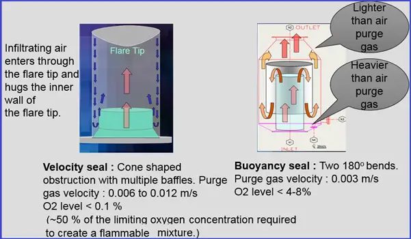
- Purge gas requirement: To avoid air ingress down the flare stack purge gas is injected in the flare header. The injection rate should be controlled by a fixed orifice, rotameter, or other devices that ensure the supply remains constant and is not subject to instrument malfunction or maladjustment.
- Purge reduction seals (Fig. 6): To reduce the purge rate purge reduction seals are used.
Liquid seal
The liquid seal drum shall be designed as a pressure vessel with a design pressure of at least 7 bar (100 psig) to maintain containment against internal deflagration.
Where there is a risk of an obstruction in the flare due to process flows creating an ice plug with the liquid seal, alternate sealing fluids such as a glycol/water mixture (60% EG & H2O freezing point –45 deg C) or other means to prevent freezing SHALL [PS] be implemented.
For LNG facilities, liquid seal drums shall not be used, since in the event of a cold release this may form an obstruction in the flare relief system.
Allowable Liquid droplet size (to avoid burning rain): Burning rain occurs when the rate of burning (depends on the type of flare) of liquid droplets is lower than the rate of settling of droplets (depends on droplet size).
Drift distances of burning liquid droplets from an inadequately designed flare system can be considerably greater than 200 ft (60 m).
If the liquid is not drained from flare gas, at a gas velocity of 3-4 m/s – liquid droplets of 1000 microns can be entrained which can cause burning rain in the flare.
Liquid droplet size allowed without burning rain
- Unassisted flares: <600 micrometer
- Steam or air-assisted: <600 micrometers (less than 1% mass)
- High pressure (if operated at least 200 kPag): <1000 micrometer (less than 1% mass)
Flare Knock Out Drum (KOD)
Design pressure of KOD:
- 5 barg (50 psig) when a liquid seal drum is located between the KO drum and a flare stack.
- 7 barg (100 psig), if there is no liquid seal drum in the system.
For a multi-process unit facility (e.g., refinery) based flare KO drum where it may not be immediately clear which unit is sending liquid to the flare, liquid space on top of LA (HH) SHALL [PS] be designed to contain the maximum emergency liquid relief rate from the largest single contingency for a period of at least 15 minutes for the unit KO drum and at least 20 minutes for the flare KO drum, without taking credit for pump out capacity.
Flare Height
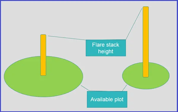
The height of the flare (Fig. 7) is established based on allowable thermal radiation levels. Flare height depends on the available plot and the distance of nearby equipment from the flare stack.
- More plot area: Low flare stack height
- Less plot area: Higher flare stack height
Thermal radiation:
The effect of thermal radiation on a person at grade or at an elevated platform shall be checked by radiation calculation.
Thermal Radiation affects human skin (skin burn).
Exposure Times Necessary to Reach the Pain Threshold
- 31 kW/m2 – Up to 20 s
- 15 kW/m2 – Up to 1 hour
- 58 kW/m2 – Continuous
If personnel exposure to radiant heat exceeds the guidelines provided, then shielding should be considered.
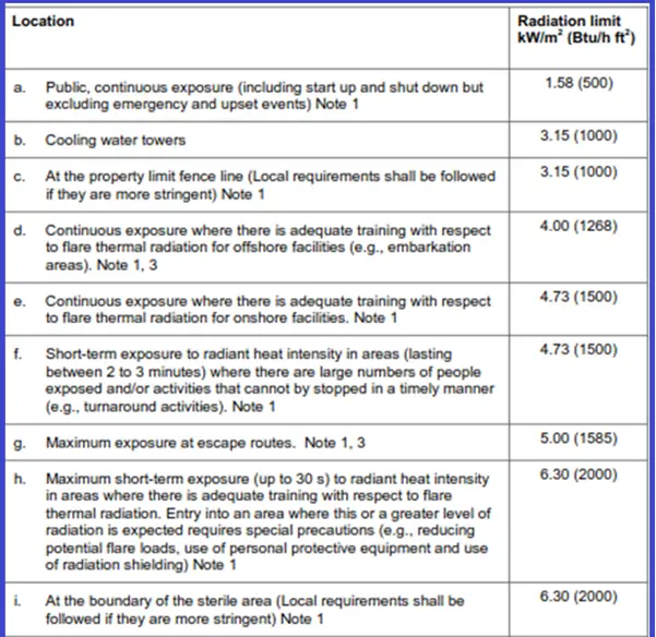
Depending on the location the thermal radiation limit is provided in Fig. 8
- The solar radiation need not be added to calculated thermal radiation values (0.79 to 1.04 kW/m2) from the Flare.
- A wind velocity of 10 m/s (22 mph) at the elevation of the flare tip, blowing towards the receiver, is a typical assumption for flame tilt assessment.
- When two flares are located in close vicinity, combined radiation effects shall be calculated.
Dispersion Analysis
To ensure safe operation during periods when the flame might have extinguished, the concentration of hazardous components should be determined using dispersion analyses, assuming the flare is functioning as a vent only.
| Level of Concern | Hydrogen Sulphide (Concentration, Time) | Sulphur Dioxide (Concentration, Time) |
| 8 Hour TWA (Threshold Limit Value) | 5 ppm, 8 hours | 2 ppm, 8 hours |
| 15 Minute STEL (Short-Term Exposure Limit) | 10 ppm, 15 minutes | 5 ppm, 15 minutes |
Short-term exposure limits (STELs) are set to help prevent effects, such as eye irritation, which may occur following exposure for a few minutes
Smokeless requirement
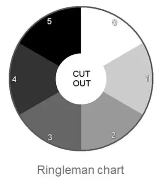
Local rules and regulations shall be followed. Typically flare combustion quality shall meet Ringelmann Index 1 criteria (Fig. 9).
Smokeless flowrate shall be the normal flow that is expected in day-to-day operations. Do not specify the design capacity for smokeless operation.
A scale used to define levels of white, gray, and black i.e. intensity of smoke
- Ringelmann No. 0 is clear smoke
- Ringelmann No. 5 is 100 percent black.
- Ringelmann No. 1 is equivalent to 20 percent black
Other requirements
- Noise: For normal flow rate (including starting-up and shutting-down): 85 dB(A) at the sterile radius. For emergency conditions: 115 dB(A) at sterile radius
- Combustion efficiency: greater than 98%
- The number of pilots (Fig. 10): The number of pilots required is a function of the flare burner diameter. For very small flares, a single pilot will reliably light the flare gas. However, it should be noted that if only a single pilot is used, a single pilot failure would represent a complete failure of the ignition system. Recommended installing at least 2 pilots for tip size of up to 8″ to increase reliability. As the flare burner diameter increases, the number of pilots required to reliably light the flare, regardless of wind direction, increases.

Flare gas recovery system Safety considerations
- Path to flare: PRVs, depressuring systems, etc., shall always have flow paths to the flare available at all times.
- Reverse flow: Because flare gas recovery systems usually involve compressors that take their suction directly from the flare header, the potential for the reverse flow of air from the flare into the compressors at low flare gas loads shall be considered.
- Monitor oxygen content in the flare header and provide recovery system trips. Provide a low-pressure trip on the recovery system suction to avoid air ingress. Liquid seal drum (not practical in AP flare systems)
Few more useful Resources for you…
Pre-Commissioning and Commissioning Checklist for Flare Package
Routing Of Flare And Relief Valve Piping: An article-Part 1
Flare systems: Major thrust points for stress analysis
Stress Analysis of PSV connected Piping Systems Using Caesar II
Articles related to Process Design
Piping Layout and Design Basics
Piping Stress Analysis Basics

Hi I enjoyed both parts of this article. The best summary I have come across. Just a couple of comments.
1. Part 1: I believe that DEP standards are specific to Shell and those who license them, so maybe best to list other more accessible European standards in addition to API.
2. Part 2: In Flare KOD section, “Design pressure of KODs: states 5 barg (50 psig) when a liquid seal drum is located between the KOD and flare stack.”, it should be 3.5 barg (50 psig) when a liquid seal drum is located between the KOD and flare stack.”
What has been your experience with specifying the number of pilots on >= 90″ tips?
It’s interesting to know the primary function of a flare is to use combustion to convert flammable, toxic, or corrosive vapors to less objectionable compounds like CO2. I never knew there were so many different types of flares. Particularly, the enclosed flares are used in plants where a visible flame is not acceptable. I finally understand why these flares are used in offshore facilities as they provide low noise and radiation levels.
What type of supports should be used for cold flare with 5meters in height?
Short flare stack, commonly use the self support. But please check the design of structure to make sure the design.
Enjoyed thoroughly reading the article..request to add information related to flare tip maintenance and handling ways.
Please check the ventury nozzle of pilot, burner, flame force, thermocouple, etc
Thanks Refer to your mention
” Thermal Radiation affects human skin (skin burn).
Exposure Times Necessary to Reach the Pain Threshold
31 kW/m2 – Up to 20 s
15 kW/m2 – Up to 1 hour
58 kW/m2 – Continuous”
Refer to your above mentioned , where this numbers refer from? cause it seems high value ?
could you more explanation
Can you design a flare system for chemical plant. Composition is Isobutylene 95% and 1 % traces of isomers and 4 % nitrogen.