This article covers the design consideration of emergency response procedures and measures in petroleum refineries, chemical plants, and similar plants. This can be used in conjunction with the Job Specification, the client’s standards and intent, the licensor’s instructions, and related regulations. This article describes the emergency response design consideration of the following emergency measures.
- ISOLATION with Emergency Shut-off Valve
- DEPRESSURIZING and
- ALARM and TRIP system
Emergency Response Measure Pressure Relieving
Of the various measures for protecting a plant from the emergency situation, pressure-relieving through safety valves and rupture discs shall be examined first. This part will be covered in separate articles.
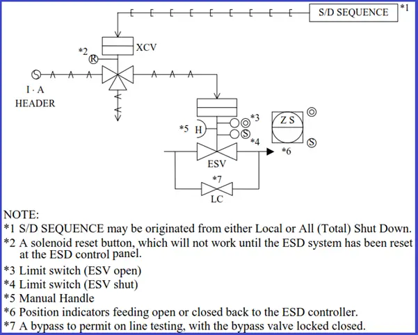
Isolation with Emergency Shut-off Valve
This section describes the installation standards of Emergency Shut-off (Block) Valves (ESV)used for isolating the equipment from the units in an emergency.
First, the following should be clarified with the client.
- Client’s general philosophy for safety
- Reliability for sensor(application of 2 out of 3 or not etc.)
- Category of ESV (local, all shut down, etc.)
- Inspection under operation (bypass or parallel installation)
The purpose of isolation by ESV is classified into the following.
- Equipment Protection (Vessel, Tower)
- Heat Off (Furnace, Steam supply)
- Fluid or Seal gas Cut(Compressor, Pump), Leak Air Cut (Vacuum Pump)
Emergency Response Plan for Vessels
- ESV is not always necessary to be provided on the Vessel outlet line.
- If both the vessel volume of liquid and fluid condition meet the following requirements, ESV shall be provided on Vessel outlet lines.
(a) Vessel volume-This limitation should be verified with project specifications.
- Liquefied Petroleum Gas of more than 100 ton
- Toxic liquid of more than 30 ton
- SRC – More than 15 ton
- EXOR – More than 20 m3
(b) Fluid condition-
- Liquid both flash point below 22.8°C and boiling point below 37.8°C
- LPG, Naphtha, liquid with temperature more than auto ignition temp.
A control valve with a solenoid valve may be used as ESV if the following conditions are met:
- It is not equipped with a minimum stop
- It will close on the failure of the air supply or power failure.
- A leak amount of CV is allowable.
- The client’s approval is obtained
Emergency Responses for Furnaces
- Fuel lines to process furnaces and steam boilers shall be provided with remotely operated emergency valves.
- In addition to the above, a manually operated block valve shall be provided in each fuel line. This includes the pilot gas supply line if it is a separate line. These valves shall be located at least 15 meters horizontally from the furnace or boiler protected.
- ESV (Emergency shut-off valve) on the snuffing steam line shall be located at least 15 meters horizontally from the furnace and operable from grade.
Emergency responses for Steam Line to Reboiler
- ESV will be installed on the steam inlet line to Reboiler especially in the case when the control valve is installed on the Reboiler outlet condensate line.
Emergency Measures for Compressors
- ESV shall be provided in the suction and discharge lines of centrifugal compressors to prevent seal gas leakage.
- (2) Other specifications for ESV installation are as below.
- In case when Control Valve closing time is too slow. (Cost study is necessary)
- A Balance line with ESV between suction and discharge may be requested by the client.
Emergency Response Plan for Pumps
- ESV will be provided in the suction line of Pumps. (Treated as Vessel Outlet ESV)
- ESV may be installed on the discharge line of high-head pumps to prevent backflow.
Emergency Response Guidelines: Vacuum Pumps
- In the case of the NASH Pump, ESV will be installed on the suction line (process side) of Vacuum Pumps to prevent seal liquid from backflow into the process.
Emergency Measures: Depressurizing
When metal is exposed to fire, the metal temperatures may reach a level at which stress rupture could occur. The use of an emergency vapor depressurizing system is one method of avoiding such an occurrence.
Design Base of Vapor Depressurizing
The design base of vapor depressurizing is as follows. (Refer to API RP 520, 521)
- Depressurizing Valve is of a remotely operated type.
- Depressurizing initial pressure may be assumed up to design pressure.
- The depressurized level should beat 7.0 kg/cm2 G or 50% of vessel design pressure, whichever is lower.
- The duration time of depressurizing should be 15 minutes with a wall thickness of 25 mm, while vessels with thinner walls generally require a somewhat greater depressurizing rate.
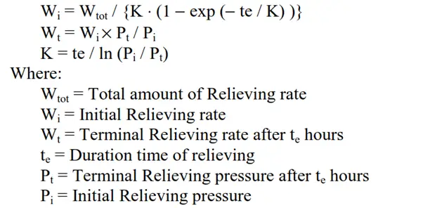
Total Vapor Depressurizing Load:
The total vapor load will be obtained as the summation of the following.
- Vapor generated from the liquid by heat input from a fire
- Density change of the vapor in the equipment during pressure reduction, plus
- Liquid flashing during pressure reduction
Design Consideration:
- For the recycle compressor stoppage, settling out pressure should be investigated.
- Excessive hot depressurizing gas should not be introduced to the flare header. Cooling should be provided in such a case.
- As for the temperature effect due to hot depressurizing gas, it is not necessary to take it into account for the determination of the design temperature of each piece of equipment because of short-term conditions. However thermal stress checks of related piping should be necessary as required.
- Regarding both pressure and flow rate change along with traveling time, the following tentative method may be available.
- The dynamic simulation should be carried out to confirm:
- RO design for Depressurizing rate.
- Reactor mechanical bed pressure checks during Depressurizing.
- H/E with differential pressure design.
- Mechanical damage for Compressor Seal Oil etc.
- (NOTE) In the case of Manual Depressurizing with HCV, the above is not necessary.
Emergency Response Procedure: Alarm and Trip System
(a) Alarm and trip signals are indicated on DCS or CCR panel. When the signal tells abnormal situations happened, it is expected that the operator takes appropriate countermeasure actions in accordance with the operating manual.
(b) As for compressor and other package units, alarm and trip signals are indicated on the local panel. Only common alarm and trip signals are indicated on DCS or CCR panel. It is expected that the operator explores the cause of the failure at the local panel and takes appropriate actions in accordance with the operating manual.
(c) Each ESD (Emergency Shut Down) shall be independent of the distributed control system (DCS) and may be activated either by plant transducers (eg. high pressure, low flow) or manually from CCR.
(d) Typical set point for level alarm and level trip
- – High / Low alarms at 80% and 20% of the range
- – High / Low trips at 90% and 10% of the range
A dedicated level switch is provided for the level trips.
A minimum of 5 minutes will be available for the operator’s intervention after a high or low-level alarm is actuated and before gas breakthrough or liquid flooding takes place. Or an independent ESV is provided for the operator to initiate manually to close the outgoing flow. (to be confirmed by the process engineer)
(e) Setpoint for temperature and pressure alarm and trip.
– As specific to the project, contents shall be individually investigated and clarified.
Emergency Response Procedure: Failures & Trips
The failures for units and equipment, as also trip actions are summarized under the following categories.
- Furnaces
- Pumps including Hydraulic Power Recovery Turbine
- Compressors
The trip sequence is summarized on the PID. It is necessary, however, to prepare the sequence logic diagram at the same time. Also, it is desirable to explain the outline of the trip sequence in the operation manual. Typical TRIP SEQUENCE is as follows.