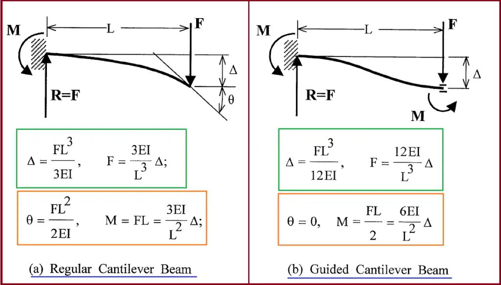
The guided Cantilever method is one of the approximate methods for piping flexibility checking. This method is widely used by piping designers to check the approximate flexibility of simple piping configurations. A Guided cantilever is a beam whose one end is fixed and the other end is held parallel to its original position. The image shown in Fig. 1 represents a Regular and Guided Cantilever beam.

Application of Guided Cantilever Method
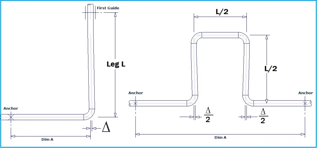
The guided cantilever beam shown in Fig. 1 is basically half of the fixed beam subject to a concentrated load. To calculate approximate forces and moments in a given length of the pipe due to thermal expansion, these beam models are often used. However, the major application of the guided cantilever method is to calculate the leg length (absorbing leg) required for a given thermal displacement. The distance of the first guide after a long straight turn or the expansion loop length in between two fixed anchors can be approximately calculated using the guided cantilever method. Refer to Fig. 2 below.

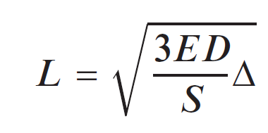
Using the guided cantilever method, the absorbing leg L, perpendicular to Dimension A (Fig. 2) can be calculated using the following Formula:

Here,
- E=Elasticity Modulus
- D=Pipe OD
- S=Allowable Stress.
- ∆=Thermal Expansion
For Carbon steel, the above equation can be approximated as L=66 (D∆)1/2
Assumptions in Guided Cantilever Method
The assumptions behind the guided cantilever method can be listed as follows:
- The piping system has only two terminal points which are composed of a straight leg of a pipe with uniform thickness and size and the square corner intersection,
- The thermal expansion is absorbed only by a leg in the perpendicular direction
- All piping legs are parallel to coordinate axes.
- The amount of thermal expansion a given length can absorb is inversely proportional to its stiffness.
- The legs act as guided cantilevers subjected to bending under end displacements and the rotation of the end is not permitted.
Limitations of the Guided Cantilever Method
The guided cantilever method is limited to simple geometries only; For complex configurations, it can not be applied.

Well Summarized, Can you include in Assumptions, the Input Units for these formulas.
The Constants associated with the formula may change with the Unit System i.e British or Metric Units.
Thanks
E/S is unitless…. the result has the same unit of D and Delta that must be the same.
el metodo es aplicable para trabajos con temperaturas criogenicas?
Is the method applicable to work in cryogenic temperatures?
yes, this approach is valid for any temperature, you just need to calculate the thermal growth delta based on your actual temperature. As point of information, for any extreme temperature (high or low), most client specifications will require a computer analysis, so this approximate method is only useful to sanity check initial layouts, and would be insufficient to document full system acceptability.