Recent Posts

What is the Pressure Equipment Directive (PED)? | PED vs ASME

Pressure Equipment Directive or PED 2014/68/EU is a legislative framework at the European level for pressure equipment presenting pressure hazards applicable to the design and fabrication of pressure equipment. This directive has been made effective throughout the EU region from 19th July 2016 onwards. As per the pressure equipment directive, any equipment (Pressure vessels, Steam boilers, Piping, Assemblies, Safety Accessories, Pressure Accessories, etc) with more than 0ne liter in volume and pressure more than 0.5 bar gauge (or 7.25 PSIG) is termed as pressure equipment. The earlier directive 97/23/EC was fully superseded by the latest pressure equipment directive 2014/68/EU from 20 July 2016 onwards.

Under the Community regime of the Pressure Equipment Directive, pressure equipment, and assemblies as defined by the directive have to be safe, must meet essential safety requirements covering design, manufacture, and testing; must satisfy appropriate conformity assessment procedures; and carry the CE marking and other information.

Exclusions from PED

As per the pressure equipment directive, the following items/equipment are excluded:

  • vessels containing liquids with pressure not more than 0.5 bar.
  • simple pressure vessels covered by Directive 2014/29/EU.
  • pipelines comprising piping or systems for carrying fluids or substances to or from an installation.
  • networks for the supply, distribution, and discharge of water and associated equipment and headraces such as penstocks, pressure tunnels, pressure shafts for hydroelectric installations, and their related specific accessories.
  • aerosol dispensers covered by Council Directive 75/324/EEC.
  • equipment and items designed for nuclear use.
  • the wellhead (Christmas tree), the blow-out preventers (BOP), the piping manifolds, and all their equipment upstream; used in the petroleum, gas, or geothermal exploration and extraction industry and in underground storage
  • high-voltage electrical equipment enclosures such as switchgear, control gear, transformers, and rotating machines;
  • exhaust and inlet silencers;
  • radiators and pipes in warm water heating systems;
  • equipment covered by Directive 2008/68/EC and Directive 2010/35/EU and equipment covered by the International Maritime Dangerous Goods Code and the Convention on International Civil Aviation;

Free Movement within the EU region

All equipment manufactured in accordance with pressure equipment directive guidelines and bearing CE marking can be moved within member states without any restrictions. However, the member states shall perform market surveillance and take all appropriate measures to withdraw the equipment liable to endanger the safety of people, domestic animals, or property.

Product Classification per Pressure Equipment Directive

A manufacturer should categorize the pressure equipment to decide the applicability of the pressure equipment directive. As per Annex II of the pressure equipment directive, there are four conformity assessment categories: Categories I to IV. Category I relates to the lowest and Category IV to the highest, hazardous category.

To determine the exact category of the equipment, the manufacturer should identify the type of equipment; fluid phase, and fluid group. Article 13 of the pressure equipment directive divides fluids into two groups; group 1 and group 2.

Group 1 of PED fluids consists of hazardous fluids like explosives, flammable solids, liquids & gases, pyrophoric liquids & solids, self-reactive substances and mixtures, oxidizing gases, liquids & solids, organic peroxides, toxic fluids, etc. Group 2 consists of all other fluids not mentioned in Group 1.

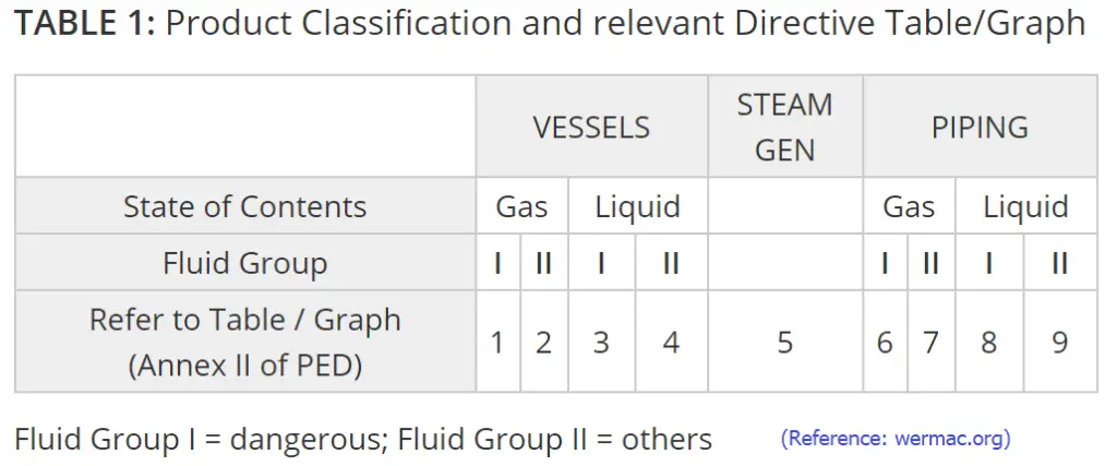
Now based on these fluid groups and conformity assessment category, Annex II provides Pressure vs Volume (for pressure vessels) or Pressure vs Nominal Size (for piping) curves. The manufacturer needs to plot similar pressure curves for their piece of equipment on the relevant Graph to identify the category of the equipment. Normally, the lower the pressure and the volume, the lower the category for the equipment. There is a total of 9 graphs or tables as mentioned in the Pressure equipment directive. Table 1 to Table 4 are for vessels, Table 5 is for Steam or general services and Table 6 to Table 9 is for piping. The following image (Fig. 1) provides a guide for selecting relevant graphs/tables for fluid groups and types of equipment.

Product Classification as per Pressure Equipment Directive
Fig. 1: Product Classification as per Pressure Equipment Directive

Pressure Equipment Directive-Conformity Assessment Procedure

Article 14 of the pressure equipment directive provides guidelines for conformity assessment procedures depending on equipment categories. 13 different conformity assessment modules are provided by the PED for assessment before the release of the equipment in the market. The following image (Fig. 2) lists the conformity modules.

Pressure Equipment Directive-Conformity assessment procedure
Fig. 2: Pressure Equipment Directive-Conformity assessment procedure

Based on product control or quality systems, manufacturers have to identify a procedure. The modules attributed to a higher hazard category may be used in lower categories. Category I is for manufacturer self-assessment.

Notified bodies appointed by the Member States should be involved during the monitoring, inspection, or approval stages for the modules for products in Categories II, III, and IV. Member states can appoint recognized third-party organizations to carry out the approval of welding procedures and personnel and non-destructive testing personnel. For Modules A1, C1, F, and G; Member states can appoint user inspectorates to carry out the tasks of notified bodies within their organizations. However, in such cases, the CE marking should not be affixed to pressure equipment and assemblies assessed by user inspectorates.

Conformity Declaration and CE-marking

Upon completion of the conformity assessment, the manufacturer is required to affix CE-marking and draw up a Declaration of Conformity for items that comply with the provision of the pressure equipment directive. The CE marking shall be affixed visibly, legibly, and indelibly to each item or assembly of pressure equipment. In situations where the affixing of the CE marking is not possible or not warranted on account of the nature of the equipment or assembly, it shall be affixed to the packaging and the accompanying documents.

Advantages of Pressure Equipment Directive

The major advantages of implementing the pressure equipment directive into force are:

  • Simplified assessment using harmonized standards.
  • Specific assessment based on hazard categories.
  • Certification
  • Free movement within the EU region
  • All products under the Pressure equipment directive meet the essential safety requirements.
  • Proper documentation.

Differences Between PED & ASME

The PED (Pressure Equipment Directive) and ASME (American Society of Mechanical Engineers) standards are both critical frameworks for ensuring the safety and reliability of pressure equipment, but they differ in several key areas. Here is a table summarizing the major differences between PED and ASME:

AspectPED (Pressure Equipment Directive)ASME (American Society of Mechanical Engineers)
Governing BodyEuropean Union (EU)American Society of Mechanical Engineers (USA)
Geographical ScopeEuropean Economic Area (EEA)Primarily USA, but widely recognized internationally
Regulatory NatureLegally binding within EU member statesVoluntary compliance, though often mandated by local laws
Certification ProcessRequires conformity assessment by a Notified BodyCertification by an Authorized Inspection Agency (AIA)
Scope of StandardsCovers design, manufacturing, and conformity assessmentCovers design, construction, inspection, and testing
Marking RequirementsCE marking for complianceASME “U” stamp or other relevant stamps for compliance
Design CodesEN standards (e.g., EN 13445)ASME Boiler and Pressure Vessel Code (BPVC)
Material RequirementsSpecific to EU standardsDetailed material specifications in ASME BPVC Section II
Inspection and TestingInvolves third-party inspection by a Notified BodyInvolves third-party inspection by an Authorized Inspector
DocumentationComprehensive technical documentation for conformityDetailed documentation and reports as per ASME code
Quality AssuranceEmphasis on quality assurance throughout the supply chainQuality assurance systems like ASME’s Nuclear Quality Assurance (NQA-1)
Updates and RevisionsPeriodically updated through EU directivesRegular updates through ASME code committees
Risk CategoriesClassified into different categories based on potential hazardUses design rules and factors of safety for different classes of equipment
Table 1: ASME vs PED

Further Studies

  • https://eur-lex.europa.eu/legal-content/EN/TXT/?uri=CELEX:02014L0068-20140717
  • https://ec.europa.eu/docsroom/documents/41641/attachments/1/translations/en/renditions/native

Differences Between SP3D and E3D in Engineering Design: E3D vs SP3D

In the piping engineering design, two software solutions stand out prominently: SP3D (SmartPlant 3D) and E3D (AVEVA Everything3D). Both are robust tools utilized by professionals across industries for plant design, construction, and operations management. While they share similar objectives, there are distinct differences between SP3D and E3D that merit exploration. In this article, we’ll find out the unique features, functionalities, and advantages of each, providing a comprehensive comparison to help professionals make informed decisions.

What is SP3D or SmartPlant 3D?

SP3D, developed by Intergraph (now part of Hexagon PPM), is a comprehensive 3D modeling software tailored specifically for the engineering, procurement, and construction (EPC) industry. It offers a holistic approach to plant design, enabling engineers to create detailed models of piping, equipment, structures, and instrumentation within a unified environment. SP3D emphasizes collaboration, efficiency, and accuracy throughout the design process.

What is E3D (AVEVA Everything3D)

E3D, developed by AVEVA Solutions Limited, is another prominent player in the field of plant design software. It boasts advanced capabilities for integrated engineering, design, and construction, aiming to streamline project execution and enhance productivity. E3D leverages cutting-edge technology to deliver a flexible and intuitive platform for multidisciplinary engineering tasks, from conceptual design to as-built documentation.

Differences between SP3D and E3D

Now, let’s delve deeper into the specific features and differences between SP3D and E3D:

User Interface and Workflow:

SP3D: Known for its user-friendly interface and intuitive navigation tools, SP3D offers a structured workflow that guides users through the various stages of plant design. The interface is customizable, allowing users to tailor their workspace to suit their preferences and optimize productivity.

E3D: E3D also prioritizes user experience with a modern interface and streamlined workflow. It provides comprehensive tools for visualization and manipulation of 3D models, facilitating collaboration among multidisciplinary teams. E3D’s interface is highly configurable, enabling users to adapt the workspace according to project requirements.

SP3D VS E3D
SP3D VS E3D

Modeling Capabilities:

SP3D: SP3D excels in detailed modeling of piping systems, equipment, and structures, offering a wide range of parametric components and libraries. Its intelligent modeling features include automatic clash detection, which helps identify and resolve spatial conflicts during the design phase.

E3D: E3D boasts powerful modeling capabilities that extend beyond traditional plant design elements. It supports the creation of complex geometries, including non-standard shapes and customized components. E3D’s flexible modeling tools enable engineers to address diverse project requirements with precision and efficiency.

Integration and Interoperability:

SP3D: As part of the Intergraph suite of engineering software, SP3D integrates seamlessly with other applications such as PDS (Plant Design System) and SmartPlant Enterprise for comprehensive project management and data exchange.

E3D: AVEVA emphasizes interoperability with third-party software and industry-standard formats, allowing seamless integration with various engineering disciplines and systems. E3D’s open architecture facilitates data exchange and collaboration across different platforms, enhancing project efficiency and flexibility.

Collaboration and Documentation:

SP3D: SP3D offers robust collaboration tools, including cloud-based project management and real-time collaboration features. It also provides comprehensive documentation capabilities for generating detailed drawings, reports, and material lists.

E3D: E3D enhances collaboration through advanced visualization and review tools, enabling stakeholders to visualize the project in different stages and provide feedback. Its documentation features support the creation of accurate and up-to-date deliverables, ensuring compliance with industry standards and regulations.

E3D vs SP3D

The major differences between E3D and SP3D that are explained above are tabulated below for quick understanding and access:

Feature/AspectE3DSP3D
DeveloperThe E3D software is developed by AVEVA Solutions LimitedThe SP3D software is developed by Intergraph (Hexagon PPM)
User InterfaceE3D has a modern interface with an intuitive workflowSP3D interface is user-friendly and easily customizable.
Modeling CapabilitiesSupports complex geometries and is flexible.Emphasis on piping, equipment, and structures.
IntegrationInteroperability with third-party systems.Seamless integration within the Intergraph ecosystem.
Collaboration ToolsAdvanced visualization, and review features.Cloud-based project management, real-time collaboration.
DocumentationSupports the creation of accurate deliverablesComprehensive documentation capabilities.
Industry FocusPlant design, construction, operationsEngineering, procurement, construction (EPC)
CustomizabilityHighly configurable interfaceCustomizable workspace, templates
Cost and LicensingCost varies based on features, licensingCost varies based on features, licensing
ScalabilityScalable to accommodate project growthScalable, suitable for large-scale projects
Training and SupportAvailable resources, supportTraining, support from Intergraph/Hexagon
Industry Standards ComplianceAdheres to industry standards, regulationsCompliance with industry standards, regulations
Table 1: E3D vs SP3D-Major Differences

SP3D or E3D: Which Software is Better?

Determining which software is “better” between SP3D and E3D depends on various factors, including the specific needs of the project, the preferences of the engineering team, and the industry standards and requirements. Both SP3D and E3D are robust solutions with their own features and advantages, and the choice between them often comes down to individual circumstances. Here are some considerations to help evaluate which software may be more suitable:

Project Requirements:

  • Consider the scope and complexity of the project. Does it involve primarily plant design, or are there additional requirements such as integrated engineering, construction, or operations management?
  • Evaluate the specific functionalities and capabilities required for the project, such as modeling precision, clash detection, documentation, and collaboration tools.

User Experience and Familiarity:

  • Assess the familiarity and proficiency of the engineering team with each software. Consider factors such as training requirements, ease of adoption, and the availability of support resources.
  • Determine which interface and workflow align better with the team’s preferences and working style.

Interoperability and Integration:

  • Evaluate the compatibility of each software with existing systems and workflows within the organization. Consider factors such as data exchange formats, interoperability with third-party software, and integration capabilities.
  • Determine whether seamless collaboration and information exchange with other disciplines and project stakeholders are critical requirements.

Industry Standards and Best Practices:

  • Consider industry-specific standards, regulations, and best practices relevant to the project. Evaluate how well each software supports compliance with these standards and facilitates adherence to industry guidelines.
  • Assess the track record of each software in similar projects or industries to gauge its suitability and reliability.

Scalability and Flexibility:

  • Consider the scalability of each software to accommodate potential future growth or changes in project requirements.
  • Evaluate the flexibility of the software in adapting to evolving project needs, including the ability to customize workflows, templates, and configurations.

Cost and Licensing:

  • Evaluate the total cost of ownership for each software, including licensing fees, maintenance, support, and training expenses.
  • Consider the value proposition of each software in terms of its features, capabilities, and return on investment over the project lifecycle.

In summary, both SP3D and E3D are powerful software solutions for plant design and engineering, each offering unique features and advantages. While SP3D emphasizes user-friendliness and integration within the Intergraph ecosystem, E3D stands out for its advanced modeling capabilities and interoperability with third-party systems. Ultimately, the choice between SP3D and E3D depends on project requirements, industry standards, and the specific needs of engineering teams.

Welding Repair: Techniques, Procedures, and Standards

Welding repair is one of the frequently used hot working methods in process industries. For industries relying on heavy equipment such as pressure vessels, the welding repair method is indispensable for maintaining operational integrity and safety. As it involves heat, pressure, and filler materials; specialized skills and knowledge are paramount for performing accurate welding repair. In this article, we will discuss the nuances of the welding repair process, explaining the fundamentals, techniques, procedures, and standards associated with welding repair.

What is Welding Repair?

Welding repair stands as a pivotal method employed to rectify damaged metal components within industrial equipment. It involves the meticulous removal of damaged material, often through arc gouging, followed by the welding of replacement metal to restore structural integrity. This process creates a robust bond by subjecting both sides of the repair area to high-temperature heat until they reach their melting point, ensuring a seamless connection.

For the Oil and Gas industries, where pressure equipment is frequently used, welding repair acts as a vital technique. Depending on the nature of the damage and the type of metal being used, the repair welding technique and process may vary. ASME PCC-2 provides detailed guidelines for repairing pressure equipment.

Welding Repair Techniques

Guided by ASME PCC-2, several endorsed techniques cater to different metals and damage types:

  1. Shielded Metal Arc Welding (SMAW): Versatile and widely used, SMAW employs a consumable electrode coated with flux to weld various metals and alloys with precision and strength.
  2. Gas Tungsten Arc Welding (GTAW or TIG): Renowned for its precision, TIG welding utilizes a non-consumable tungsten electrode and often requires a separate filler metal to join metal parts, making it ideal for intricate repairs.
  3. Gas Metal Arc Welding (GMAW or MIG): GMAW, utilizing a continuous wire electrode and shielding gas, offers rapid and efficient welding, making it suitable for large-scale industrial repairs.
  4. Flux Cored Arc Welding (FCAW): FCAW employs a tubular wire containing flux to provide a protective gas shield and additional filler metal, making it versatile for diverse metal types and repair scenarios.
  5. Submerged Arc Welding (SAW): With its high deposition rates and deep penetration, SAW is commonly utilized in heavy industrial applications, employing granular flux to shield and provide additional filler metal for robust repairs.

Welding Repair Procedures

Stringent procedures ensure adherence to quality and safety standards throughout the repair process:

Preparation for Welding:

Prioritizing safety, thorough cleaning, disassembly, and protection of adjacent machinery are paramount. Proper alignment markers, preheating, cutting, and gouging set the stage for effective repair.

Repair Welding:

Executing the prescribed welding procedure with precision and care, ensuring proper equipment, materials, alignment, and sequences. Consistent inspection maintains weld quality throughout.

Postweld Operation:

Inspection for quality, comprehensive cleanup, repainting, and meticulous reassembly of components ensure the integrity and longevity of the repaired equipment.

Steps for Successful Repair Welding

Repair welding involves a series of meticulous steps to ensure the effective restoration of damaged metal components. Here’s a detailed breakdown of the repair welding process:

Welding Procedure Preparation:

Before commencing repair welding, it’s crucial to have the welding procedure readily available. This document outlines the specific welding process and joint technique required for the repair. Common techniques include arc welding, gas welding, and TIG welding. The following video clearly explains the method of welding repair

Welding Repair Methodogy for ASME Pressure Vessels

Welding Equipment Setup:

Ensure sufficient welding equipment is available to avoid delays in the repair process. This includes welding machines, holders, grinders, wire feeders, cables, and other necessary tools. Standby equipment may also be necessary to address any unforeseen issues.

Material Preparation:

Adequate materials, including filler metals stored properly, should be accessible for the entire repair job. This includes insert pieces, reinforcing pieces, and other materials required for the repair. Additionally, ensure the availability of fuel for preheating, shielding gases if used, and fuel for engine-powered welding machines.

Alignment Markers Placement:

Alignment markers may be employed before welding to ensure proper alignment of the components being repaired. These markers, often simple center punch marks made across the joint at different locations, aid in maintaining alignment throughout the welding process.

Welding Sequences Determination:

Determine the appropriate welding sequence for the repair job. This could include block welding, back-step sequence welding, wandering sequence welding, or peeling, depending on the nature of the repair and the welding procedure specified.

Weld Quality Inspection:

Throughout the welding process, continuously inspect the quality of the welds being produced. Ensure that the final weld is smooth and free from any defects such as notches or lack of fusion. If necessary, perform grinding to maintain smooth contours and ensure structural integrity.

Standards Governing Welding Repair

Adherence to standards is essential for safety, quality, and compliance. The most common codes and standards that are followed for repair welding techniques are

  1. ASME B31.3 – Process Piping: Addressing design, fabrication, inspection, and testing of process piping systems, including welding processes, to ensure industry compliance and safety.
  2. ASME BPVC Section VIII – Rules for Construction of Pressure Vessels: Outlining welding and fabrication requirements for pressure vessels across industries, emphasizing structural integrity and performance.
  3. ASME PCC-2: Providing comprehensive guidelines for repairing pressure equipment, offering effective solutions and steps for utilizing repair welding techniques in compliance with industry standards.

The Need for Welding Repair and Maintenance

Welding repair and maintenance play a crucial role in ensuring the longevity, reliability, and safety of industrial equipment across various sectors. Here’s why welding repair and maintenance are indispensable:

Equipment Longevity:

Welding repair and maintenance are essential for extending the lifespan of industrial equipment. According to a report by MarketsandMarkets, the global industrial machinery market size is projected to reach USD 771.5 billion by 2026, indicating a significant investment in machinery across industries. Regular maintenance and timely repair of components through welding help prevent premature failure and extend the operational life of machinery.

Safety Compliance:

Safety is paramount in industrial settings, especially in sectors such as oil and gas, manufacturing, and construction. According to the Occupational Safety and Health Administration (OSHA), failure to maintain industrial equipment properly can result in accidents, injuries, and even fatalities. Welding repair ensures that equipment meets safety standards, reducing the risk of workplace accidents and ensuring compliance with regulatory requirements.

Downtime Reduction:

Unplanned downtime due to equipment failure can result in significant losses for industries. A study by Aberdeen Group found that unplanned downtime costs industrial manufacturers an average of $260,000 per hour. Welding repair and proactive maintenance help minimize downtime by addressing issues before they escalate into major failures. This proactive approach improves operational efficiency and reduces production losses.

Cost Savings:

Effective welding repair and maintenance strategies can lead to significant cost savings for industries. According to a study published in the Journal of Quality in Maintenance Engineering, implementing a preventive maintenance program can result in cost savings of up to 20% compared to reactive maintenance approaches. By addressing issues early through welding repair, industries can avoid costly replacements and prolong the service life of equipment.

Asset Performance Optimization:

Welding repair and maintenance contribute to optimizing asset performance and enhancing productivity. A report by McKinsey & Company highlights the importance of predictive maintenance in maximizing asset utilization and minimizing downtime. By leveraging welding repair techniques and advanced maintenance strategies, industries can improve asset reliability, reduce maintenance costs, and achieve higher levels of productivity.

What is Mobile Welding Repair?

Mobile welding repair refers to the provision of welding services at the client’s location, rather than at a fixed workshop or facility. This service offers a range of benefits, including convenience, flexibility, and efficiency. Here are 7 significant benefits of mobile welding repair services:

  1. On-Site Convenience
  2. Rapid Response
  3. Flexibility in Location
  4. Tailored Solutions
  5. Cost-Effective Approach
  6. Quality and Precision
  7. Versatility in Services

The following video shows a typical mobile TIG welding repair on stainless steel

Example of Mobile Welding Repair

Teflon vs PTFE: Major Differences | Applications of PTFE in the Piping Industry

It is really difficult sometimes to find out “what actually means what”. PTFE vs Teflon is such an example. Our universe is full of technical jargon, acronyms, and trade names. So, to find out the major differences between PTFE and Teflon, and which one is better between Teflon and PTFE, let’s understand what PTFE and Teflon are all about.

What is PTFE?

PTFE is an acronym or short form of polytetrafluoroethylene, a synthetic polymer consisting of carbon and fluorine. PTFE is originated from tetrafluoroethylene and widely used in a range of applications due to its several unique properties.

Properties of PTFE

The useful properties that make PTFE a versatile product are

High melting point: PTFE has a melting point of around 327°C. They are thermally stable in between -200°C and +260°C. So, it can not be damaged easily by heat and that is the reason PTFE has found extensive applications as non-stick cookware.
Thermal Resistance: Good resistance to heat, light, UV, and weathering.

Hydrophobic: This is a unique property of PTFE. It does not get wet by water or water-containing substances.
Chemically inert: PTFE is highly insoluble and not damaged by the majority of solvents and chemicals.
Low coefficient of friction: The friction coefficient of PTFE is lower than most solids. So it helps PTFE to work as a non-sticky material. That is the reason PTFE plates are sometimes provided below pipe shoes to reduce support friction.

High flexural strength: Even at lower temperatures PTFE retains its ability to bend and flex. This helps PTFE to be applied on a variety of surfaces without losing its integrity.
High electrical resistance: PTFE offers high electrical resistance. That’s why this is used in between different materials to isolate electrically to avoid corrosion.
High Density: PTFE’s density is also very high, around 2200 kg/m3.

Other properties of PTFE are tabulated below:

PropertyValue
Melting Temperature (°C)317-337
Tensile Modulus (MPa)550
Elongation at Break (%)300-550
Young’s Modulus (GPa)0.5
Dielectric strength (kV/mm)19.7
Dielectric Constant2.0
Dynamic Coefficient of Friction0.04
Surface Energy (Dynes/g)18
Appl. Temperature (°C)260
Refractive Index1.35
Thermal expansion112–125×10−6 K−1
Bulk resistivity (Ω·cm)1018
Table 1: Properties of PTFE

Applications of PTFE in Piping and Pipeline Industries

Polytetrafluoroethylene (PTFE) is widely used in the piping and pipeline industry due to its exceptional chemical resistance, low friction coefficient, and high-temperature stability. Its unique properties make it an ideal material for various applications, ranging from sealing components to lining systems. Here are some common applications of PTFE in the piping and pipeline industry:

  • PTFE O-rings, gaskets, and seals are used to create reliable and leak-free connections in piping systems. PTFE’s chemical inertness ensures compatibility with a wide range of fluids, including corrosive chemicals and aggressive media.
  • PTFE seals are particularly suitable for high-pressure and high-temperature applications where conventional elastomeric seals may degrade or fail.
  • PTFE expansion joints are used to absorb thermal expansion and contraction in piping systems, reducing stress on pipes, valves, and equipment.
  • PTFE’s low coefficient of friction allows for smooth movement and flexibility, making it ideal for accommodating dynamic movements and vibrations in pipelines.
  • PTFE lining systems are employed to protect metallic pipes and equipment from corrosion and chemical attacks in aggressive environments.
  • PTFE-lined pipes, fittings, and vessels provide a chemically inert barrier that prevents contact between corrosive fluids and the underlying substrate, extending the service life of the equipment.
  • PTFE-lined pipe fittings, such as elbows, tees, reducers, and flanges, are used in chemical processing plants, refineries, and industrial facilities to transport corrosive fluids safely.
  • PTFE-coated bolts, nuts, and fasteners offer corrosion resistance and ease of installation in harsh environments, reducing maintenance requirements and ensuring reliable operation.
  • PTFE valve seats and seals are utilized in ball valves, butterfly valves, diaphragm valves, and other types of valves to provide tight shutoff and long-term reliability.
  • PTFE’s low friction coefficient and resilience to deformation ensure smooth operation and minimal wear, even in applications with abrasive or viscous fluids.
  • PTFE coatings are applied to the interior surfaces of pipelines and storage tanks to provide a protective barrier against corrosion, fouling, and buildup of deposits.

Some other applications of PTFE can be found

  • for coating inside pipe surfaces to carry corrosive fluids.
  • as pipe support elements along with pipe shoes or trunnions to reduce support friction.
  • as electrically isolating material between pipe and clamps.
  • to isolate the transfer of vibration from the piping to structures.
  • as absorbant for accoustic vibration.
  • It is used as a lubricant as well.
  • as coatings for bolts, nuts, etc.
Typical Applications of PTFE

Other Applications of PTFE

Other applications of PTFE include Fabric and Carpet protection, Chemical and steel industries, Containers, Nail Polish, Cookware, Wiper Blades, Hairstyling tools, Artificial body parts, water-proof furniture, medical applications, musical instruments, etc. Even Teflon Tapes are widely used in plumbing applications. The following videos show some of the great uses of PTFE in plumbing applications.

Applications of TEFLON Tape in Plumbing

Drawbacks of PTFE

The disadvantages of PTFE are

  • Sensitivity to creep and abrasion.
  • Difficulties of joining.
  • Low radiation resistance
  • Corrosive and prone to toxic fumes.

However, the main drawback of PTFE is that

at temperatures above 200°C Pyrolysis (thermal decomposition) of PTFE is detectable. It evolves several fluorocarbon gases and a sublimate that causes significant health issues. So for cookware applications where the temperature reaches above 260°C, it should not be used.

For piping applications, the PTFE-coated pipes can not withstand the heat of welding.

What is Teflon?

To find out the differences between Teflon vs PTFE, we have to first understand what Teflon means. Teflon was discovered in 1938 by the DuPont scientist Dr. Roy Plunkett. Teflon is also a fluorinated plastic containing carbon and fluorine. Yes, you guessed it right, both PTFE and Teflon are the same. Teflon is the registered trademark name or brand name for PTFE owned by Chemours. So, there is no difference or better between PTFE vs Teflon. The only difference is in the name. PTFE is the actual product and Teflon is the brand name.

PTFE vs Teflon

By now it must have been clear that PTFE and Teflon both refer to the same product called polytetrafluoroethylene, a synthetic rubber with versatile applications. To find out a winner between PTFE vs Teflon, we can represent that all Teflons are PTFE, but all PTFE may not be Teflon. PTFE has other brand names as well. Commercially, PTFE is also available with the following brand names:

  • 3M™ Dyneon™, 3M-Dyneon
  • Flontech®, Flontech
  • Fluon®, AGC
  • POLYFLON™, Daikin

Hope, with the above discussion the differences between Teflon and PTFE, or Teflon vs PTFE are properly addressed.

What is Metal Galling? Its Causes, Mechanism, Susceptible Metals, Prevention

Metal galling is a type of surface wear that causes metal to unintentionally engage with another metal in contact. Metal galling phenomena can result in the separation of metal pieces from the original component. The process of metal galling is quite rapid and once initiated can lead to component failure with subsequent operating cycles.

The galling mechanism in metals is quite different from other wear mechanisms due to the adhesion it creates. Contrary to other types of wear processes, metal galling causes the metal to adhere to the other material and is unique. Whereas, other wear forms involve erosion of one metal when in contact with another metal.

The effect of galling in metals can be at varying levels; Large or microscopic levels. Microscopic galling is not easily visible. Large metal galling can easily be seen on metal surfaces by the naked eye. Even though microscopic galling does not make the component completely useless, but still it can cause performance failure for components with tight tolerances.

Causes of Metal Galling

Galling in metals occur because of large frictional forces that cause adhesive wear. This usually happens when two or more metals are in contact with one another under the influence of very high loads. Ductile materials having a crystal structure that promotes cohesive attraction are ideal for metal galling. Many of industrial metals exhibit both of these characteristics and that is why galling is quite a common phenomenon among most metals. The frictional force gives the required energy for adhesion to occur. So for galling to occur all the following three factors need to be present:

  • High frictional force
  • Ductility of material (One softer than the other), and
  • Cohesive attraction

Mechanism of Metal Galling : How does galling work?

Upon compressing one metal surface over another, they merge at the contact zone. The contact zone is the highest force point. When these compressive forces are large enough, friction is created and the pressure in the contact zone is also increased. The energy generated by this friction and pressure, causes adhesion between the two surfaces, welding the two materials together and plastically deforming them. The protruding points if available on any one of the surfaces can easily penetrate the surface oxide layer of the opposing material, causing damage to the metal beneath.

Now, when sliding friction occurs, the strong adhesion turns into galling. In the contact zone, the amount of stress increases which enables the two surfaces to break away from each other and dissolve the contact zone. This causes one material to lose particles to the other.

Galling of Threads
Fig. 1: Galling of Threads

What does Galling look like?

Galling typically appears as surface damage or wear on metal components that are in sliding or rubbing contact with each other under pressure. Some common visual indications of galling include:

  1. Surface Scuffing: This involves the formation of scratches, grooves, or rough patches on the metal surface due to friction and material transfer between the mating surfaces.
  2. Discoloration: Galled surfaces may exhibit discoloration, often appearing as darkened or discolored areas resulting from the intense heat generated by friction during the rubbing process.
  3. Adhesion Marks: Galling can cause material from one metal surface to adhere to the other, leaving behind visible marks or patches where material transfer has occurred.
  4. Rounded Edges: The edges of components may become rounded or flattened due to plastic deformation caused by the repeated sliding or rubbing action, especially at points of contact.
  5. Surface Smearing: Galled surfaces may show signs of material transfer or smearing, where material from one surface is physically transferred and deposited onto the other surface.
  6. Surface Roughness: Galling can increase the surface roughness of metal components, making them feel rough or uneven to the touch.
Examples of Galling Surfaces
Fig. 2: Examples of Galling Surfaces

Metals Susceptible to Galling

Austenitic Stainless Steel, Aluminum, and Titanium are the most prominent metals that frequently encounter galling issues. Martensitic stainless steels, tool steels, or other similar hardened materials are less likely to have metal galling occur.

When Does Galling Occur?

Applications involving two or more ductile materials imposing high frictional forces on one another are susceptible to galling. The most frequent instances of galling are found on fasteners made of Stainless steel and aluminum. While torquing, all such fasteners result in high frictional forces that are the prime component for metal galling to occur. Machinery subjected to excess friction is also at risk for galling.

How to Prevent Galling?

As metal galling can result in component failure leading to hazards, It must be prevented to occur. The factors that impact metal galling are

  • Material
  • Applied Load
  • Lubrication and Coating
  • Surface finish and Hardness
  • Contact Area and Degree of Movement

A number of ways are prevalent in metal industries to prevent galling. Some of such methods for galling prevention are:

  • Selecting a metal not prone to galling like hardened tool steels, work-hardened austenitic stainless steels, etc.
  • Applying lubricants to reduce friction between surfaces. In recent times, anti-galling lubricants containing molybdenum compounds and anti-galling coatings are also available.
  • Selecting a coarser thread to reduce the amount of friction in threaded fasteners.
  • Reduction of thread tightening speed reduces frictional heating and the risk of galling. Manual tightening will help in such cases.
  • Keeping the metal contact surfaces clean, and free from debris.
  • Reducing the load values between contacting metallic surfaces.
  • The use of dissimilar materials with low ductility or different grades of materials can reduce the galling effect.
  • Bolts with dented or damaged threads increase the potential for galling. So, always clean and damage-free bolts need to be selected.
  • Increasing contact area to lower the stresses below the threshold galling stress
  • Increasing contact area to spread wear volume over a greater area and thus producing less depth of wear.

What is galling in metal?

Galling in metals is a problem that occurs when two contacting surfaces seize up due to cold welding.

What causes metal to gall?

The main cause of metal galling is friction force and adhesion. The sufficient friction force between contact surfaces causes adhesive wear.

What is anti-Gallant?

Anti-gallants are coatings used on metal surfaces to minimize the friction between rubbing surfaces and thus prevent the galling effect.

What is galling in stainless steel?

The seizure of stainless steel components causing severe adhesive wear is known as stainless steel galling. Because of the galling mechanism in stainless steel, components may become weak or even break.

What are the factors that affect the galling in stainless steel?

The factors that can impact the galling mechanism in metals are:

  • Design
  • Applied load
  • Contact area and degree of movement
  • Lubrication
  • Surface finish and hardness

What is the galling resistance chart of materials?

The metal galling resistance chart is a representation that provides typical galling resistance characteristics for material combinations when used to rub against each other. A typical galling resistance chart is produced below as a sample.

galling resistance chart for materials
Fig. 3: Galling resistance chart for materials

What hardness prevents galling in metals?

If both the metals have a hardness difference of at least 50 Brinell (20 Rc) then they harden at different rates and it reduces chances of metal galling.

Differences between Welding and Galling

Both welding and galling are different phenomena. Welding is a fabrication method for joining metals. Galling is a form of surface damage that occurs when two metal surfaces under pressure begin to adhere to each other, leading to friction, material transfer, and wear. The major differences between them are tabulated below:

AspectWeldingGalling
DefinitionJoining process that fuses materials together using heat and/or pressureSurface damage caused by friction between mating metal surfaces
OccurrenceDeliberately performed during fabrication or repairUnintended and undesirable during operation
PurposeCreates a strong, permanent bond between materialsLeads to wear and potential failure of components
MechanismFusion of materials at the atomic levelMaterial transfer and surface damage
TemperatureRequires high temperatures to melt and fuse materialsOccurs at relatively lower temperatures due to friction
LocationTypically occurs at specific joints or seamsCan occur anywhere metal surfaces rub against each other
EffectsIntended to strengthen and join materialsCan weaken components and lead to operational issues
EquipmentRequires welding equipment and expertiseNo specialized equipment required
PreventionControlled welding parameters and techniquesProper lubrication and material selection
Table 1: Welding vs Galling

What is an Example of Galling?

A common example of galling occurs is threaded fasteners, such as bolts and nuts, when they are tightened together under pressure. Some other typical examples are:

  • Shafts and Bearings: In rotating machinery, such as engines, pumps, and gearboxes, shafts and bearings can experience galling when insufficient lubrication or improper surface finishes lead to friction between the mating surfaces. This can result in scoring, wear, and reduced performance of the equipment.
  • Valves and Valve Seats: In valves used in hydraulic systems, engines, or pipelines, galling can occur between the valve stem and the valve seat due to repeated opening and closing actions. The high pressure and friction between the mating surfaces can cause material transfer and surface damage, affecting the sealing performance of the valve.
  • Sliding Contact Surfaces: Any metal components in sliding contact, such as gears, cams, sliders, and tracks, can experience galling if proper lubrication is lacking or if the materials have incompatible properties. Galling in these components can lead to increased friction, wear, and even system failure if left unchecked.
  • Pipe Fittings and Flanges: Galling can occur in pipe fittings, connectors, and flanges used in piping systems due to the tightening of threaded connections or the mating of flange faces. This can lead to damage to the sealing surfaces, compromising the integrity of the piping system and potentially causing leaks.
  • Fastening Systems: Galling can also occur in non-threaded fastening systems, such as press-fit assemblies, where metal surfaces come into contact under pressure. This can lead to material transfer, deformation, and impaired functionality of the fastening system.
  • Piping Shoe Supports and Structural Members

Let’s take a look at the following video to understand the metal galling in threads.

Reason for Metallic Thread Galling and Its Prevention

Shear Modulus or Modulus of Rigidity: Definition, Significance, Example

Shear Modulus is defined as the ratio of shear stress to the corresponding shear strain within a material’s proportional limit. Also known as modulus of rigidity and rigidity modulus, the shear modulus is denoted by “G” and can be experimentally determined from the slope of the shear stress (τ) vs shear strain (γ) curve.  The more the value of the shear modulus or modulus of rigidity, the more rigid the material is. The shear modulus values of engineering materials are determined by torsional tests. It is a measure of a material’s resistance to deformation under shear stress.

Shear Modulus Units

The SI unit of modulus of rigidity or shear modulus is the Pascal (Pa). However, it is popularly expressed in gigapascals (GPa). The unit of shear modulus in the English system is a thousand pounds per square inch (KSI). Its dimensional form is M1L−1T−2.

Shear Modulus Formula

On the application of a shear force on a body, it deforms laterally. So, the shear modulus is basically a measure of the material’s ability to resist transverse deformation. Large shear forces can create a flow in the material. Mathematically, the formula for shear modulus can be expressed as follows:

Shear Modulus, G=Shear Stress (τ)/Shear Strain (γ)

Now Shear stress= Shear Force (F)/ Area (A) and Shear Strain= Change in Length (Δ) in the lateral direction/Original length(L). Hence

The formula for Shear Modulus, G=FL/AΔ

The relationship of Shear Modulus (G) with Young’s modulus (E) and Poisson’s ratio (μ) is given below:

E=2G(1+μ) or G = E/(2(1+μ)

Characteristics of Shear Modulus or Modulus of Rigidity

  • Modulus of rigidity is a material property and remains constant for a material at a specific temperature.
  • The shear modulus is independent of the geometry of the material.
  • With an increase in temperature, the modulus of rigidity decreases.
  • A high value of modulus of rigidity means it will maintain its shape and a large force will be required to deform it, and a low value of shear modulus signifies the material is soft or flexible.
  • Fluids (Liquids and Gases) have the minimum value of rigidity modulus (0) and they started flowing with a little application of shear force.
  • Diamond has the maximum value of shear modulus (478 GPa).
  • Shear Strength is the maximum value of shear stress that a material can withstand without fracture or failure.

Shear Modulus of Steel and Other Materials

The shear modulus of carbon steel is 77 GPa and the same for stainless steel is 77.2 GPa. The modulus of rigidity of water is considered zero. The modulus of rigidity values at room temperature for other common materials are tabulated below:

MaterialShear Modulus or Modulus of Rigidity in GPaMaterialShear Modulus or Modulus of Rigidity in GPa
Aluminum Alloys25-27Tin18
Aluminum24-28Titanium, Grade 241
Beryllium Copper48Titanium, Grade 541
Brass40Titanium, 10% Vanadium42
Bronze44.8Tungsten161
Cadmium19Wood, Douglas Fir13
Nickel76Zinc43
Cast Iron41Z-nickel76
Chromium115Steel, Cast78
Concrete21Steel, Cold-rolled75
Copper45Plywood0.62
Glass26.2Polycarbonate2.3
Glass, 96% silica19Polyethylene0.12
Inconel79Rubber0.0006
Iron, Ductile63 – 66Structural Steel79.3
Iron, Malleable64Monel metal66
Kevlar19Nickel Silver48
Lead13.1Nickel Steel76
Magnesium16.5Nylon4.1
Molybdenum118Phosphor Bronze41
Diamond478Wood 4
Chalk3.2Granite24
Table 1: Rigidity Modulus Values for Common Materials

Importance of Shear Modulus in Engineering

Modulus of Rigidity or Shear Modulus plays a crucial role in various engineering applications, particularly in structural and mechanical engineering. Here are some key reasons why the shear modulus is important:

  • Material Strength: The shear modulus is an indicator of a material’s strength and stiffness under shear loading conditions. Materials with higher shear modulus values are generally stronger and more resistant to deformation when subjected to shear stress. This property is essential in designing structures and components that can withstand applied loads without failure.
  • Elastic Deformation: The shear modulus determines the amount of elastic deformation a material undergoes when subjected to shear stress. It defines the relationship between shear stress and shear strain in the elastic region of the material’s stress-strain curve. Understanding this relationship is critical for predicting the behavior of materials under loading conditions and ensuring that structures remain within their elastic limits to avoid permanent deformation.
  • Material Selection: Engineers use the shear modulus to compare the mechanical properties of different materials and select the most suitable material for a particular application. For example, in the design of mechanical components, choosing materials with appropriate shear modulus values can ensure that the components meet performance requirements while minimizing weight and cost.
  • Structural Analysis: The shear modulus is essential in structural analysis and design, particularly in determining the stiffness and stability of various structural elements, such as beams, columns, and shafts. It influences parameters such as deflection, bending stress, and torsional rigidity, which are critical considerations in the design of safe and efficient structures.
  • Material Behavior Prediction: Knowledge of the shear modulus allows engineers to predict how materials will respond to different types of loading, including shear, torsion, and bending. This information is invaluable in designing structures and components that can withstand various types of mechanical stresses encountered during operation.
  • Material Characterization: The shear modulus is a key parameter used in material characterization and testing. Experimental techniques such as torsion testing and shear wave propagation methods are employed to measure the shear modulus of materials accurately. These measurements provide valuable data for material selection, quality control, and research purposes.

Differences between Shear Modulus and Young’s Modulus

Both Young’s modulus and shear modulus are measures of a material’s stiffness, they apply to different types of stress and deformation. Young’s modulus is concerned with linear deformation under tensile or compressive stress, whereas shear modulus is concerned with angular deformation under shear stress.

Here’s a tabulated summary highlighting the main differences between Young’s modulus (also known as the modulus of elasticity in tension or compression) and shear modulus (also known as the modulus of rigidity):

AspectYoung’s ModulusShear Modulus
DefinitionMeasure of a material’s resistance to linear deformation under tensile or compressive stressMeasure of a material’s resistance to shear deformation under shear stress
SymbolEG or S
Types of StressTensile or Compressive StressShear Stress
Types of DeformationLinear (stretching or compressing)Angular (twisting or shearing)
Formula𝐸=StressStrainE=StrainStress​𝐺=Shear StressShear StrainG=Shear StrainShear Stress​
UnitsPascals (Pa)Pascals (Pa)
Material BehaviorReflects resistance to stretching or compressingReflects resistance to shearing or twisting
ApplicationUsed in the design and analysis of structures under tensile or compressive loadsUsed in the design and analysis of structures under shear loads
Table 2: Young’s Modulus vs Shear Modulus

If you still have doubts about shear modulus or rigidity modulus, then I recommend the following video lecture:

Shear Modulus or Rigidity Modulus