Recent Posts

What is a Solenoid Valve and What is its Types?

What is a Solenoid Valve?

A solenoid valve is an electromechanical valve that operates using an in-built actuator in the form of an electrical coil and a plunger. An electrical signal controls the opening and closing of the solenoid valve. There are two modes in which solenoid valves are produced. They are normally open and normally closed. The solenoid (electrical coil) is operated using an AC or DC. DC supply is provided through a battery, generator, or rectifier. Whereas an AC supply is usually taken from AC mains voltage, through a transformer.

What is a Solenoid valve used for?

A solenoid valve is used to open, close, mix, or divert liquid and gaseous media in an application. Solenoid valves find wide applications in industrial as well as domestic sectors. The use of solenoid valves ranges from the control of standard process valves to the control of specific valves like overpressure protection systems and emergency stop valves, as well as fluid control in applications like fire system valves. The major advantage of a solenoid valve compared to traditional valves is the very fast response time. Some of the common applications include:

  • Solenoid valves in refrigeration systems reverse the refrigerant flow that cools during summer and heats during winter.
  • Solenoid valves are used in compressors during the starting phase to discharge the compressor in order to reduce the torque on the engine.
  • Solenoid valves are used in irrigation systems for automatic control purposes.
  • Solenoid valves in washing machines and dishwashers control the water flow as per requirement.
  • Air pressure in air conditioning systems is controlled by solenoid valves.
  • Automatic locking systems for door locks use solenoid valves.
  • Car washes and Industrial cleaning equipment use solenoid valves to control the water, soap, or chemical flow.
  • The inflow and outflow of water in water tanks are often controlled using solenoid valves.
  • The pressure, flow, and fluid direction in controlled by solenoid valves in dental and various medical equipment.

Working of a Solenoid Valve

A solenoid valve has two main components: a solenoid and a valve body (G). The following figure (Fig. 1) shows the typical components of a solenoid valve. The electromagnetically inductive coil (A) around an iron core at the center is known as the plunger (E). At rest, it will be either normally open (NO) or normally closed (NC). During the de-energized phase, a normally open valve remains open while a normally closed valve remains closed. When current flows through the solenoid coil, it is energized and creates a magnetic field that creates a magnetic attraction with the plunger. Because of this, the plunger moves by overcoming the spring (D) force. For a normally closed solenoid valve, the plunger is lifted and the seal (F) opens the orifice allowing the media to flow through the valve. While for a normally open solenoid valve, the plunger moves downward and the seal (F) blocks the orifice which stops the media from flowing through the valve. The shading ring as denoted by (C) in Fig. 1 prevents vibration and humming in AC coils.
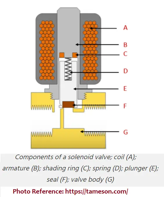
Components of a Solenoid Valve
Fig. 1: Components of a Solenoid Valve

Solenoid valves are used to control the flow of liquids and gases automatically. In the most varied types of plants and equipment, they are being used to an increasing degree. A variety of different designs are available to suit a particular application.

Types of Solenoid Valves

Depending on the number of pipe connections Solenoid valves are classified into three groups.

  • Two-Way Solenoid Valves and
  • Three-Way solenoid Valves
  • Four-Way Solenoid Valves

Two-Way Solenoid Valves

As the name suggests, a two-way solenoid valve has one inlet and one outlet piping connection. They can be categorized into the following two types.

  • Normally closed construction: The valve is closed when de-energized and open when energized.
  • Normally open construction: This type of Solenoid valve is closed when energized and open when de-energized.

Three-way Solenoid valves

Three-way solenoid valves have three pipe connections and two orifices. When one orifice is open the other is closed and vice versa. Three-way solenoid valves are commonly used alternatively to apply pressure to and exhaust pressure from a diaphragm valve or single-acting cylinder. They operate in the following three modes:

Normally closed construction: When the valve is de-energized, the pressure port is closed and the exhaust port is connected to the cylinder port. With the valve energized, the pressure port is connected to the cylinder port and the exhaust port is closed.

Normally open construction: The pressure port is connected to the cylinder port when the valve is de-energized. But when the valve is energized the pressure port is closed and the cylinder port is connected to the exhaust port.

Universal construction: This type allows the valve to be connected in either the normally closed or normally open position. In addition, the valve may be connected to select one or two ports or to divert flow from one port to another.

Four Way Solenoid valves

Four-way solenoid valves are used to operate double-acting cylinders. These types of solenoid valves have four or five pipe connections; One pressure, two-cylinder, and one or two exhausts. In one valve position, the pressure is connected to the cylinder port; the other is connected to the exhaust. In the other valve position, pressure and exhaust are reversed at the cylinder connections.

Depending on the functions of the solenoid valves, they are classified as

  • General-purpose solenoid valves
  • Safety shut-off valves and
  • Process-control valves

General-purpose solenoid valves: This type of solenoid valve is either a normally open or normally closed valve used for controlling the flow of a fluid. However, these valves do not act as safety valves.

Safety shut-off valve: This is normally a closed valve of the “on” or “off” type that actuates using a safety control device for preventing unsafe fluid delivery. A multiple-port valve can work as a safety shut-off valve with respect to its normally closed port.

Process-control valve: These type of solenoid valves are approved to control flammable gases but does not reliably work as a safety shut-off valve.

Depending on the working methodology, solenoid valves are classified into four groups as follows:

  • Direct-acting solenoid valves
  • Pilot-operated solenoid valves
  • Pressure-operated solenoid valves
  • Air-operated solenoid valves

Direct-acting solenoid valves

In a direct-acting solenoid valve, the core directly opens the orifice of a normally closed valve or closes the orifice of a normally open valve. The orifice size and fluid pressure decide the force required to open the valves. With an increase in the orifice size, the force required also increases.

Pilot-operated solenoid valves

This type of solenoid valve is equipped with a pilot and a smaller orifice. They utilize the line pressure for operation. When the solenoid is energized, the pilot orifice is opened and it immediately releases the pressure from the top of the valve piston or diaphragm to the outlet of the valve. This causes an unbalanced pressure which forces the line pressure to lift the piston of the diaphragm off the main orifice and open the valve.

When the solenoid is de-energized, the pilot orifice is closed and full line pressure is applied to the top of the piston or diaphragm through the orifice, producing a sealing force for tight closure. There are two common types of construction:

  • floating diaphragm or piston
  • hung-type diaphragm or piston.

Pressure-operated solenoid valve

These types of solenoid valves are usually diaphragm or piston-operated valves. They are normally equipped with a 3-way or 4-way solenoid pilot that controls the opening or closing of the main valve using operating pressure.

Air-operated solenoid valves

This solenoid valve type has two basic functional units.

  • an operator with a piston or diaphragm assembly that develops a force upon pressurization.
  • a valve with an orifice in which a plug or disc is positioned to allow or stop the flow.

A piston is normally used for pneumatic operation whereas low and instrument air-pressure range operators typically use a diaphragm.

Solenoid Valve Enclosures

Depending on the application of the solenoid valves, the solenoid coils are enclosed using various types of enclosures. Their main purpose is to protect the coil from dust, indirect splashing, water, etc.

Selection of Solenoid Valves

The selection of a specific type of solenoid valve is not easy. A number of physical and operating factors are required to be decided when selecting a solenoid valve for a particular application. Some of these parameters are:

Pressure:

There are various pressure terms that should be known prior to solenoid valve selection. They are:

  • The maximum operating pressure differential that the electrical solenoid has to overcome for opening or closing the valve must be known during the selection process.
  • Similarly, the minimum pressure drop that will exist across the valve during flowing is also required.
  • Safe static pressure at which the valve will be subjected during normal service.
  • Proof pressure is usually considered 5 times the safe working pressure.

Temperature:

Similar to the pressure mentioned above, the following temperatures should be known:

  • Minimum, Maximum, and Normal ambient temperatures
  • Maximum fluid temperature

Viscosity:

The viscosity of the flowing fluid at the operating temperature is also an important parameter during solenoid valve selection.

Response time:

The response time of a valve is the time-lapse for the solenoid valve to go from the open to a closed position or vice versa. Depending on the valve size, the response time of a solenoid valve varies. It is also dependent on the type of electrical supply, fluids handled, temperature, pressure, and pressure drop.

Type of solenoid valve:

Depending on the application requirement, the necessity of a 2-way or 3-way solenoid valve has to be determined. Decide beforehand if the specific application requires a direct, indirect, or semi-direct operated solenoid valve.

Solenoid valve housing material:

Based on the chemical properties and temperature of the flowing media and the environment, the valve housing material is determined. Common solenoid valve housing materials are Brass, Stainless steel, PVC, and polyamide.

Solenoid Valve Sizing

Sizing and selection of the appropriate type of solenoid valve are highly essential as both undersized and oversized valves have various undesirable effects. The basic factors that are considered during solenoid valve sizing are

  • Minimum and maximum flow to be controlled.
  • Minimum and maximum pressure differential across the solenoid valve
  • Specific gravity, temperature, and viscosity of the fluid handled.
  • Inlet and outlet pipe diameter.
  • Supply voltage.

The optimal size of a solenoid valve is decided by determining the flow rate, which allows for determining the flow factor (kv). The flow factor indicates the volume of water at room temperature that flows through the solenoid valve with a pressure drop of 1 bar for one minute.

Solenoid Valve Symbol

Similar to other valves, There is a specific symbol for solenoid valves. Fig. 2 below shows the Solenoid valve symbol representation.
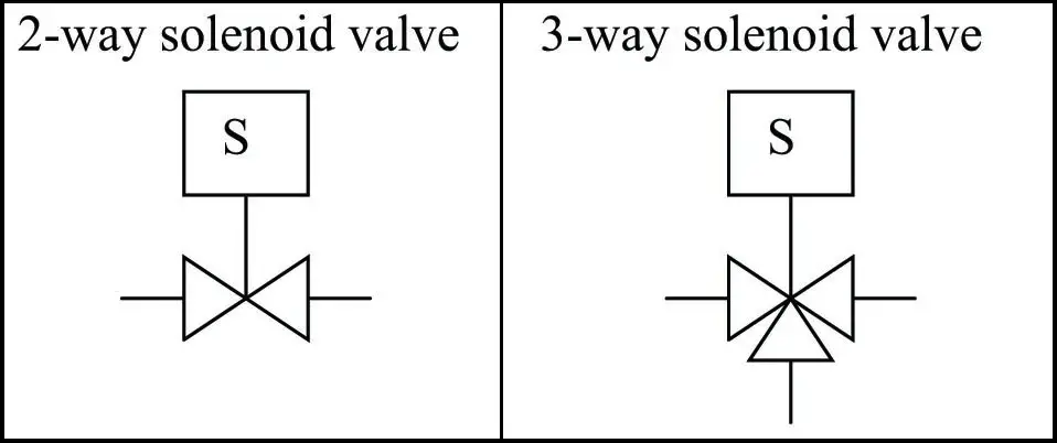
Solenoid Valve Symbol
Fig. 2: Solenoid Valve Symbol

Bonney Forge Valves and Pipe Fittings: Bonney Forge Catalogue

In the realm of industrial manufacturing, few companies boast a legacy as rich and esteemed as Bonney Forge. With a history dating back over a century, Bonney Forge has cemented its position as a global leader in the forging industry. It is renowned for its extensive range of high-quality forged steel fittings, valves, and related products that cater to various industries. As a reliable supplier to critical industries for over a century, Bonney Forge continues to uphold its commitment to quality, safety, and customer satisfaction in all its product offerings.

Products from Bonney Forge

Some of the key product categories offered by Bonney Forge include:

Forged Steel Fittings:

Bonney Forge manufactures a wide array of forged fittings, including elbows, tees, couplings, unions, cross fittings, caps, and plugs. These fittings are designed to provide reliable connections in piping systems and are available in various sizes, pressure ratings, and materials to meet diverse industrial requirements.

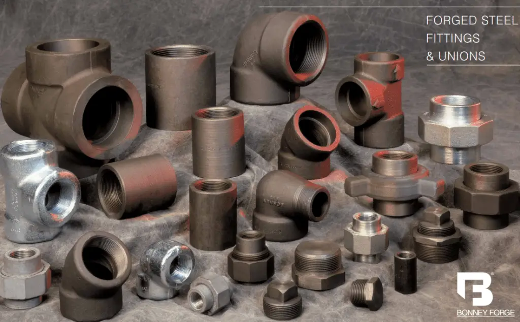
Bonney Forge Fittings refer to a comprehensive range of forged steel fittings manufactured by Bonney Forge. These fittings are used for connecting, terminating, or branching pipes in industrial piping systems. Bonney Forge Fittings are known for their precision, reliability, and compliance with industry standards, making them a preferred choice for various industries with critical applications. Fig. 1 below shows some of the typical Bonney Forge Products.

Bonney Forge Fittings and Unions
Fig. 1: Bonney Forge Fittings and Unions

Forged Steel Valves:

Bonney Forge produces a comprehensive selection of forged steel valves, including gate valves, globe valves, check valves, and ball valves. These valves are designed for critical applications in oil and gas, petrochemicals, power generation, and other industries, ensuring smooth flow control and safety.

Bonney Forge Gate valves are linear-motion valves used to control the flow of fluid by raising or lowering a wedge-shaped gate to either open or close the passageway. Bonney Forge Gate Valves are designed for high-pressure and high-temperature applications and are commonly used in oil and gas pipelines, refineries, and other industrial settings.

Specialty Products:

Apart from standard fittings and valves, Bonney Forge offers specialty products such as Swage Nipples, Bull Plugs, and Reducers. Swage Nipples are used for connecting different pipe sizes, while Bull Plugs are solid plugs used to close the ends of pipes. Reducers are used to join pipes of different sizes together seamlessly.

Bonney Forge Unions

A Bonney Forge Union is a type of pipe fitting used to join two pipes or fittings together in a piping system. Unions are designed to provide a convenient and detachable connection that allows for easy maintenance and disassembly of the system without needing to cut or permanently weld the pipes.

Oil Patch Fittings and Oilfield Products:

Bonney Forge specializes in producing fittings and products specifically designed for the demanding conditions of the oil and gas industry. These include Hammer Unions, API Flanges, Pup Joints, Crossovers, and more.

Branch Connections:

Bonney Forge’s branch connection products include Weldolet, Thredolet, Sockolet, Latrolet, Elbolet, Sweepolet, and Nipolet. These specialized fittings allow for the creation of branch connections in pipelines without the need for complex welding.

A Bonney Forge Weldolet is a specific type of branch connection fitting designed to provide an outlet from a larger pipe to a smaller one through welding. Weldolets are used to create a strong and leak-proof branch connection in a piping system. Bonney Forge Weldolets are manufactured to stringent standards, ensuring a high-quality and reliable connection.

High-Pressure Fittings and Valves:

Bonney Forge offers a range of high-pressure fittings and valves suitable for applications where extreme pressure and temperature conditions are present.

Carbon Steel, Stainless Steel, and Exotic Alloy Products:

The company offers fittings and valves made from various materials, including carbon steel, stainless steel, and exotic alloys like Inconel, Monel, and Hastelloy, to meet specific corrosion resistance and temperature requirements.

Bonney Forge MTR:

The Bonney Forge Material Test Report, commonly known as MTR, is a document that provides detailed information about the materials used in the manufacturing of Bonney Forge products. It includes important data such as chemical composition, mechanical properties, heat treatment details, and compliance with industry standards. The MTR is crucial for ensuring the quality and traceability of the materials used in Bonney Forge products.

Bonney Forge Catalogue

The Bonney Forge Catalogue is a comprehensive document or publication that contains detailed information about the products offered by Bonney Forge. This includes specifications, technical details, applications, and product codes for their extensive range of forged steel fittings, valves, and related products. The catalog serves as a valuable reference for customers, engineers, and procurement professionals when selecting and sourcing Bonney Forge products for their specific needs. You can download the latest available Bonney Forge Catalogue from here.

Conclusion

In conclusion, Bonney Forge’s journey from a modest workshop in the late 19th century to a global industry leader today is a testament to the power of innovation, dedication, and quality. With a legacy spanning over a century, the company’s unwavering commitment to customer satisfaction, environmental responsibility, and employee well-being makes it an exemplar for others in the forging industry. As we move towards a future driven by technology and sustainability, Bonney Forge stands poised to continue forging connections that empower industries worldwide.

Please note that product names and offerings may change or evolve over time, so it is always a good idea to refer to the latest Bonney Forge documentation or website for the most up-to-date information.

Online Courses on Piping Design and Engineering

If you wish to dig deeper and learn more about elements of piping design and engineering then the below-mentioned online courses will help you to do so:

What is MSS SP-58 and Why Is It Important?

In the world of industrial and commercial piping systems, ensuring the safe and efficient support of pipes is crucial. One key resource that plays a pivotal role in achieving this goal is MSS SP 58, a standard developed by the Manufacturer’s Standardization Society of the Valve and Fittings Industry (MSS). In this blog post, we’ll delve into MSS SP 58, exploring what it is, why it’s important, and how it impacts various industries.

What is MSS SP 58?

MSS SP 58, also known as “Pipe Hangers and Supports – Materials, Design, Manufacture, Selection, Application, and Installation,” is a set of guidelines, fabrication criteria, and recommendations for the design, manufacture, selection, application, and installation of pipe hangers and supports. These elements are essential to maintaining the integrity and stability of piping systems in diverse industries.

Adequate pipe support is a must for the piping system to work efficiently for its designed life. The MSS SP-58 establishes an industry-accepted basis for pipe hangers and supports and their components of all service temperatures.

The MSS SP-58 guidelines mainly cover the following:

  • Allowable stresses
  • Load ratings
  • Minimal requirements for materials used in hangers and supports
  • Product designs
  • Standard and unique pipe support designs
  • Inspection and Testing requirements
  • Installation guidelines
  • Assembly drawing guidelines
  • Packing, Shipping, and Storage procedures, etc

The Importance of MSS SP 58

Safety

Safety is paramount when it comes to piping systems. MSS SP 58 helps ensure that the pipe hangers and supports used are designed and installed to withstand the weight, pressure, and environmental conditions they’ll encounter. This minimizes the risk of accidents, such as pipe failures or leaks, which could result in damage, injuries, or even loss of life.

Efficiency

Efficiency in industrial and commercial operations is directly tied to the functionality of piping systems. Properly designed and installed pipe hangers and supports reduce stress on the pipes and prevent sagging or misalignment. This, in turn, enhances the efficiency and longevity of the system, reducing maintenance costs and downtime.

Compliance

Many industries are subject to regulations and standards to ensure the safety and quality of their products and processes. MSS SP 58 provides a recognized and standardized framework that helps companies comply with industry regulations and codes.

MSS SP-58
MSS SP-58

Key Components of MSS SP 58

MSS SP 58 covers a wide range of topics related to pipe hangers and supports. Some key components include:

Material Selection

The standard provides guidance on selecting appropriate materials for hangers and supports, taking into consideration factors such as corrosion resistance, load-bearing capacity, and environmental conditions.

Design Considerations

MSS SP 58 outlines the design requirements for pipe hangers and supports, including factors like load calculations, spacing, and deflection limits. Proper design is essential to ensure the reliability and safety of the system.

Manufacturing Requirements

Manufacturers must adhere to certain specifications when producing pipe hangers and supports to ensure they meet the standards for quality and performance outlined in MSS SP 58.

Application and Installation

The standard offers guidelines for the correct application and installation of pipe hangers and supports, including details on spacing, anchoring, and load distribution.

MSS SP 58, the standard for pipe hangers and supports, plays a crucial role in the safety, efficiency, and compliance of industrial and commercial piping systems. By providing guidelines for material selection, design, manufacturing, and installation, MSS SP 58 helps ensure that these systems function reliably and safely.

For industries that rely on complex piping networks, adhering to MSS SP 58 is not just a matter of meeting regulatory requirements; it’s a fundamental step towards protecting assets, employees, and the environment while optimizing operational efficiency. As technology and industry practices evolve, staying up-to-date with standards like MSS SP 58 is essential to keep piping systems in peak condition.

MSS SP-58 FAQ

What is MSS SP 58 Standard?

MSS SP 58 is a standard developed by the Manufacturer’s Standardization Society of the Valve and Fittings Industry (MSS). It provides guidelines and recommendations for the design, manufacture, selection, application, and installation of pipe hangers and supports used in industrial and commercial piping systems.

Why is MSS SP 58 important?

MSS SP 58 is important because it ensures the safety, efficiency, and compliance of piping systems. It helps prevent accidents, enhances system performance, and ensures that piping systems meet industry regulations and codes.

Who should use MSS SP 58?

MSS SP 58 is relevant to a wide range of professionals and industries involved in piping systems, including engineers, designers, manufacturers, installers, and inspectors.

What does MSS SP 58 cover?

MSS SP 58 covers various aspects related to pipe hangers and supports, including material selection, design considerations, manufacturing requirements, and guidelines for application and installation.

How does MSS SP 58 enhance safety?

MSS SP 58 enhances safety by providing guidelines for designing and installing pipe hangers and supports that can withstand the weight, pressure, and environmental conditions they will encounter. This reduces the risk of accidents, such as pipe failures or leaks.

How does MSS SP 58 improve efficiency?

Properly designed and installed pipe hangers and supports, as per MSS SP 58, reduce stress on piping systems, preventing sagging or misalignment. This enhances system efficiency, reduces maintenance costs, and minimizes downtime.

What are some key design considerations outlined in MSS SP 58?

Design considerations covered in MSS SP 58 include load calculations, spacing requirements, and deflection limits. These factors are crucial for ensuring the reliability and safety of piping systems.

Are there specific installation guidelines in MSS SP 58?

Yes, MSS SP 58 offers guidelines for the correct application and installation of pipe hangers and supports. This includes details on spacing, anchoring, and load distribution.

What is the Latest Edition of MSS SP 58?

At the time of writing this article, the latest edition of MSS SP 58 is 2018 edition.

Is MSS SP 58 regularly updated?”

Standards like MSS SP 58 are periodically reviewed and updated to incorporate new industry knowledge and best practices. It’s essential to check for the latest version to ensure compliance with the most current standards.

Design of Oxygen Pipeline for Cold Blast Enrichment in a Steel Plant – A Case Study

Steel is the backbone of the modern Construction industry. The biggest advantage of making anything in steel is that it is recyclable, cheap, and durable. Today, worldwide the most popular method of steel making is Blast Furnace – Basic Oxygen Furnace route or BF- BOF route. A Blast furnace (BF), is a type of metallurgical furnace used to produce industrial metals, generally pig iron. Blast refers to the combustion air, which is supplied at a positive pressure, into the Blast Furnace bottom with the help of Blast Furnace blowers.

The combustion air (first called cold blast) goes to the stoves where it gets heated to around 1200 Deg C ( after which it is called hot blast ) and then it enters the blast furnace through its bottom to create an air curtain which supports the whole Blast Furnace burden of coke, iron ore, limestone, etc ( charged from the top ) and allows the burden to drop down slowly from top to bottom so that proper combustion and reduction of iron ore can take place and liquid hot metal is produced. Oxygen enrichment of the cold blast is generally done in order to reduce the rate of consumption of coke in the Blast Furnace therefore increasing the overall energy efficiency of the plant. Dedicated Oxygen lines are laid from suitable tapping points in the plant Oxygen network up to the Cold Blast Headers for Blast Enrichment purposes.

The stepwise procedure for laying such an Oxygen pipeline considering the design parameters, site layout constraints, Finite Element Analysis Reports, pipe support selections, flexibility analysis, 3-dimensional pipeline drawing view preparation, etc are discussed briefly here.

Flow Scheme showing the Blast Furnace Cold Blast enrichment process
Fig.1: Flow Scheme showing the Blast Furnace Cold Blast enrichment process
Flow Scheme of Cold Blast line, showing the new Oxygen enrichment line
Fig. 2: Flow Scheme of Cold Blast line, showing the new Oxygen enrichment line

It is seen from the flow scheme in Figure 2, that five Turbo-blowers (TB-1 to TB-5) in the Blower
House generates the Cold Blast air which feeds all the three individual Cold Blast headers going to
BF-1, BF-2 and BF-3 respectively. The new DN 500 Oxygen enrichment line is also shown to be
tapped near tower DTW- 116 which is laid up to tower DTW 109 for discharging the enrichment
Oxygen on to the Cold Blast line there.

A portion of Flow Scheme of Oxygen service, showing the new DN 500 Oxygen enrichment line going to BF-2 stoves
Fig. 3: A portion of the Flow Scheme of Oxygen service, showing the new DN 500 Oxygen
enrichment line going to BF-2 stoves
3D View of the Cold Blast Line and the proposed DN 500 Oxygen line over existing towers from DTW 116 to DTW 109
Fig. 4: 3D View of the Cold Blast Line and the proposed DN 500 Oxygen line over existing towers from DTW 116 to DTW 109.

Figure. 4 shows the 3-dimensional view of the existing DN 1600 Cold Blast Line and the new
proposed DN 500 Oxygen line to be laid from DTW-116 to DTW-109. The bigger blue line is the
cold blast line and the black line below it is the Oxygen Line. The location of the towers/trestles
over which these lines are passing is also indicated in Figure 4.

Support Locations and support types at different towers for the proposed DN 500 Oxygen line
Table.1: Support Locations and support types at different towers for the proposed DN 500 Oxygen line

The Design Criteria for selecting these towers/trestles for laying the Oxygen pipe are explained in
brief as follows: –

  • All available towers/trestles were designed way 30 years ago and were loaded to their maximum operating piping load. All free space in the towers/trestles was also exhausted by large and small diameter pipes at different racks of different elevations.
  • Minimum clearance height had to be maintained from plant-finished ground level as per standard practice of Steel Plants. Hence the loading capacity of the towers/trestles was limited both in the up-down direction as well as in the sideways direction. Also, to cater to pigging operations, Oxygen pipelines are always designed with 5D long radius Bends which always take more space than other pipes.
  • Pipe size cannot be reduced by increasing the velocity of flow. If velocity is increased, then firstly it can cause vibration which is undesired for old, rusted structures. Secondly, increased velocity leads to higher impingement velocity leading to pitting and faster erosion of the oxygen pipes.
  • Hence flow velocity in Oxygen pipelines is always restricted to 8 m/s. For optimization purposes, a pipe size of DN 500 was chosen and thickness was selected as per Schedule 40. For the bends, the pipe thickness was selected as per Schedule 80.
  • The pipe support span was selected based on a maximum vertical deflection of 2.5 mm. Based on this pre-condition, the maximum span limit is found to be 11.02 m. Design pressure is taken as 500 KPa. The design temperature is taken as 60 degrees C. 7000 cycles are considered for this pipe as the failure limit.

To provide the supports for the new DN 500 Oxygen pipe from existing old, rusted towers/trestles
(which were packed with other service pipelines) was difficult.

Hence the route had to be reviewed to find out the suitable locations/elevations of the structure from where new structural members could be erected considering the stability of both the existing structures and the new pipe. After a thorough study, the route from DTW-116 to DTW-109 was chosen. Here the location/ route layout of the new pipe is mainly guided by the availability of free space in pipe racks over towers/trestles where new pipe supports could be provided.

Elevation of the new pipe continuously changed throughout its course while moving from DTW-116 to DTW-109 as indicated in Table 2.

Pipe Elevation at various Towers/trestles from DTW-116 to DTW-109.
Table. 2: Pipe Elevation at various Towers/trestles from DTW-116 to DTW-109.

The ups and downs of pipe routing were used for the flexibility of the piping. Hanger supports were provided at some portions of the pipe routing for the following reasons: –

  • It was impossible to provide Structural members at those elevations.
  • To reduce the axial load at those structures that were within the permissible values of the operating load.
Pipe operational loading at different support locations
Table. 3: Pipe operational loading at different support locations

The theories of failure as considered – “Maximum Shear Stress Theory” and Piping Code
followed is ANSI B31.3.

Design parameters for the proposed DN 500 Oxygen line
Table. 4: Design parameters for the proposed DN 500 Oxygen line
SW ISO view and NW ISO view from CAESAR software of the model of DN 500 Oxygen Pipeline with node numbers marked on it.
Fig. 5: SW ISO view and NW ISO view from CAESAR software of the model of DN 500 Oxygen Pipeline with node numbers marked on it.
Plan 2D view of the Cold Blast Line and DN 500 Oxygen line showing the Tower Numbers
Fig. 6: Plan 2D view of the Cold Blast Line and DN 500 Oxygen line showing the Tower Numbers
Cross section of Structures at various Towers showing proposed DN 500 Oxygen line
Fig. 7: Cross section of Structures at various Towers showing proposed DN 500 Oxygen line
Detail of interconnection of DN 500 Oxygen line with DN 1600 Cold Blast Line near DTW 109
Fig. 8: Detail of interconnection of DN 500 Oxygen line with DN 1600 Cold Blast Line near DTW 109

The Design Results for this application have been shown in various preceding tables and figures of the current paper. The physical condition of the entire Oxygen piping system after commissioning has tallied well with the obtained design results. The DN 500 Oxygen Pipe for Cold Blast Enrichment has been successfully commissioned and has been in operation for the past year. All the design objectives are fulfilled and the DN 1600 Cold Blast Line is enriched with Oxygen.

What is the Pressure Equipment Directive (PED)? | PED vs ASME

Pressure Equipment Directive or PED 2014/68/EU is a legislative framework at the European level for pressure equipment presenting pressure hazards applicable to the design and fabrication of pressure equipment. This directive has been made effective throughout the EU region from 19th July 2016 onwards. As per the pressure equipment directive, any equipment (Pressure vessels, Steam boilers, Piping, Assemblies, Safety Accessories, Pressure Accessories, etc) with more than 0ne liter in volume and pressure more than 0.5 bar gauge (or 7.25 PSIG) is termed as pressure equipment. The earlier directive 97/23/EC was fully superseded by the latest pressure equipment directive 2014/68/EU from 20 July 2016 onwards.

Under the Community regime of the Pressure Equipment Directive, pressure equipment, and assemblies as defined by the directive have to be safe, must meet essential safety requirements covering design, manufacture, and testing; must satisfy appropriate conformity assessment procedures; and carry the CE marking and other information.

Exclusions from PED

As per the pressure equipment directive, the following items/equipment are excluded:

  • vessels containing liquids with pressure not more than 0.5 bar.
  • simple pressure vessels covered by Directive 2014/29/EU.
  • pipelines comprising piping or systems for carrying fluids or substances to or from an installation.
  • networks for the supply, distribution, and discharge of water and associated equipment and headraces such as penstocks, pressure tunnels, pressure shafts for hydroelectric installations, and their related specific accessories.
  • aerosol dispensers covered by Council Directive 75/324/EEC.
  • equipment and items designed for nuclear use.
  • the wellhead (Christmas tree), the blow-out preventers (BOP), the piping manifolds, and all their equipment upstream; used in the petroleum, gas, or geothermal exploration and extraction industry and in underground storage
  • high-voltage electrical equipment enclosures such as switchgear, control gear, transformers, and rotating machines;
  • exhaust and inlet silencers;
  • radiators and pipes in warm water heating systems;
  • equipment covered by Directive 2008/68/EC and Directive 2010/35/EU and equipment covered by the International Maritime Dangerous Goods Code and the Convention on International Civil Aviation;

Free Movement within the EU region

All equipment manufactured in accordance with pressure equipment directive guidelines and bearing CE marking can be moved within member states without any restrictions. However, the member states shall perform market surveillance and take all appropriate measures to withdraw the equipment liable to endanger the safety of people, domestic animals, or property.

Product Classification per Pressure Equipment Directive

A manufacturer should categorize the pressure equipment to decide the applicability of the pressure equipment directive. As per Annex II of the pressure equipment directive, there are four conformity assessment categories: Categories I to IV. Category I relates to the lowest and Category IV to the highest, hazardous category.

To determine the exact category of the equipment, the manufacturer should identify the type of equipment; fluid phase, and fluid group. Article 13 of the pressure equipment directive divides fluids into two groups; group 1 and group 2.

Group 1 of PED fluids consists of hazardous fluids like explosives, flammable solids, liquids & gases, pyrophoric liquids & solids, self-reactive substances and mixtures, oxidizing gases, liquids & solids, organic peroxides, toxic fluids, etc. Group 2 consists of all other fluids not mentioned in Group 1.

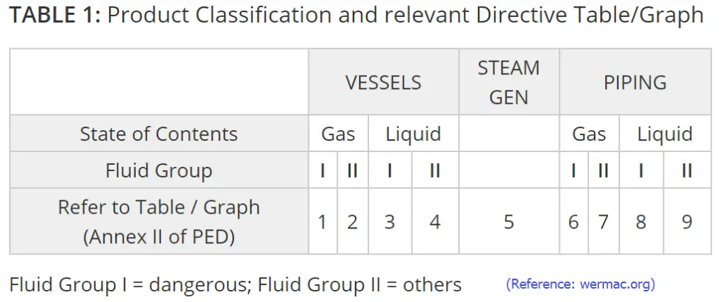
Now based on these fluid groups and conformity assessment category, Annex II provides Pressure vs Volume (for pressure vessels) or Pressure vs Nominal Size (for piping) curves. The manufacturer needs to plot similar pressure curves for their piece of equipment on the relevant Graph to identify the category of the equipment. Normally, the lower the pressure and the volume, the lower the category for the equipment. There is a total of 9 graphs or tables as mentioned in the Pressure equipment directive. Table 1 to Table 4 are for vessels, Table 5 is for Steam or general services and Table 6 to Table 9 is for piping. The following image (Fig. 1) provides a guide for selecting relevant graphs/tables for fluid groups and types of equipment.

Product Classification as per Pressure Equipment Directive
Fig. 1: Product Classification as per Pressure Equipment Directive

Pressure Equipment Directive-Conformity Assessment Procedure

Article 14 of the pressure equipment directive provides guidelines for conformity assessment procedures depending on equipment categories. 13 different conformity assessment modules are provided by the PED for assessment before the release of the equipment in the market. The following image (Fig. 2) lists the conformity modules.

Pressure Equipment Directive-Conformity assessment procedure
Fig. 2: Pressure Equipment Directive-Conformity assessment procedure

Based on product control or quality systems, manufacturers have to identify a procedure. The modules attributed to a higher hazard category may be used in lower categories. Category I is for manufacturer self-assessment.

Notified bodies appointed by the Member States should be involved during the monitoring, inspection, or approval stages for the modules for products in Categories II, III, and IV. Member states can appoint recognized third-party organizations to carry out the approval of welding procedures and personnel and non-destructive testing personnel. For Modules A1, C1, F, and G; Member states can appoint user inspectorates to carry out the tasks of notified bodies within their organizations. However, in such cases, the CE marking should not be affixed to pressure equipment and assemblies assessed by user inspectorates.

Conformity Declaration and CE-marking

Upon completion of the conformity assessment, the manufacturer is required to affix CE-marking and draw up a Declaration of Conformity for items that comply with the provision of the pressure equipment directive. The CE marking shall be affixed visibly, legibly, and indelibly to each item or assembly of pressure equipment. In situations where the affixing of the CE marking is not possible or not warranted on account of the nature of the equipment or assembly, it shall be affixed to the packaging and the accompanying documents.

Advantages of Pressure Equipment Directive

The major advantages of implementing the pressure equipment directive into force are:

  • Simplified assessment using harmonized standards.
  • Specific assessment based on hazard categories.
  • Certification
  • Free movement within the EU region
  • All products under the Pressure equipment directive meet the essential safety requirements.
  • Proper documentation.

Differences Between PED & ASME

The PED (Pressure Equipment Directive) and ASME (American Society of Mechanical Engineers) standards are both critical frameworks for ensuring the safety and reliability of pressure equipment, but they differ in several key areas. Here is a table summarizing the major differences between PED and ASME:

AspectPED (Pressure Equipment Directive)ASME (American Society of Mechanical Engineers)
Governing BodyEuropean Union (EU)American Society of Mechanical Engineers (USA)
Geographical ScopeEuropean Economic Area (EEA)Primarily USA, but widely recognized internationally
Regulatory NatureLegally binding within EU member statesVoluntary compliance, though often mandated by local laws
Certification ProcessRequires conformity assessment by a Notified BodyCertification by an Authorized Inspection Agency (AIA)
Scope of StandardsCovers design, manufacturing, and conformity assessmentCovers design, construction, inspection, and testing
Marking RequirementsCE marking for complianceASME “U” stamp or other relevant stamps for compliance
Design CodesEN standards (e.g., EN 13445)ASME Boiler and Pressure Vessel Code (BPVC)
Material RequirementsSpecific to EU standardsDetailed material specifications in ASME BPVC Section II
Inspection and TestingInvolves third-party inspection by a Notified BodyInvolves third-party inspection by an Authorized Inspector
DocumentationComprehensive technical documentation for conformityDetailed documentation and reports as per ASME code
Quality AssuranceEmphasis on quality assurance throughout the supply chainQuality assurance systems like ASME’s Nuclear Quality Assurance (NQA-1)
Updates and RevisionsPeriodically updated through EU directivesRegular updates through ASME code committees
Risk CategoriesClassified into different categories based on potential hazardUses design rules and factors of safety for different classes of equipment
Table 1: ASME vs PED

Further Studies

  • https://eur-lex.europa.eu/legal-content/EN/TXT/?uri=CELEX:02014L0068-20140717
  • https://ec.europa.eu/docsroom/documents/41641/attachments/1/translations/en/renditions/native

Differences Between SP3D and E3D in Engineering Design: E3D vs SP3D

In the piping engineering design, two software solutions stand out prominently: SP3D (SmartPlant 3D) and E3D (AVEVA Everything3D). Both are robust tools utilized by professionals across industries for plant design, construction, and operations management. While they share similar objectives, there are distinct differences between SP3D and E3D that merit exploration. In this article, we’ll find out the unique features, functionalities, and advantages of each, providing a comprehensive comparison to help professionals make informed decisions.

What is SP3D or SmartPlant 3D?

SP3D, developed by Intergraph (now part of Hexagon PPM), is a comprehensive 3D modeling software tailored specifically for the engineering, procurement, and construction (EPC) industry. It offers a holistic approach to plant design, enabling engineers to create detailed models of piping, equipment, structures, and instrumentation within a unified environment. SP3D emphasizes collaboration, efficiency, and accuracy throughout the design process.

What is E3D (AVEVA Everything3D)

E3D, developed by AVEVA Solutions Limited, is another prominent player in the field of plant design software. It boasts advanced capabilities for integrated engineering, design, and construction, aiming to streamline project execution and enhance productivity. E3D leverages cutting-edge technology to deliver a flexible and intuitive platform for multidisciplinary engineering tasks, from conceptual design to as-built documentation.

Differences between SP3D and E3D

Now, let’s delve deeper into the specific features and differences between SP3D and E3D:

User Interface and Workflow:

SP3D: Known for its user-friendly interface and intuitive navigation tools, SP3D offers a structured workflow that guides users through the various stages of plant design. The interface is customizable, allowing users to tailor their workspace to suit their preferences and optimize productivity.

E3D: E3D also prioritizes user experience with a modern interface and streamlined workflow. It provides comprehensive tools for visualization and manipulation of 3D models, facilitating collaboration among multidisciplinary teams. E3D’s interface is highly configurable, enabling users to adapt the workspace according to project requirements.

SP3D VS E3D
SP3D VS E3D

Modeling Capabilities:

SP3D: SP3D excels in detailed modeling of piping systems, equipment, and structures, offering a wide range of parametric components and libraries. Its intelligent modeling features include automatic clash detection, which helps identify and resolve spatial conflicts during the design phase.

E3D: E3D boasts powerful modeling capabilities that extend beyond traditional plant design elements. It supports the creation of complex geometries, including non-standard shapes and customized components. E3D’s flexible modeling tools enable engineers to address diverse project requirements with precision and efficiency.

Integration and Interoperability:

SP3D: As part of the Intergraph suite of engineering software, SP3D integrates seamlessly with other applications such as PDS (Plant Design System) and SmartPlant Enterprise for comprehensive project management and data exchange.

E3D: AVEVA emphasizes interoperability with third-party software and industry-standard formats, allowing seamless integration with various engineering disciplines and systems. E3D’s open architecture facilitates data exchange and collaboration across different platforms, enhancing project efficiency and flexibility.

Collaboration and Documentation:

SP3D: SP3D offers robust collaboration tools, including cloud-based project management and real-time collaboration features. It also provides comprehensive documentation capabilities for generating detailed drawings, reports, and material lists.

E3D: E3D enhances collaboration through advanced visualization and review tools, enabling stakeholders to visualize the project in different stages and provide feedback. Its documentation features support the creation of accurate and up-to-date deliverables, ensuring compliance with industry standards and regulations.

E3D vs SP3D

The major differences between E3D and SP3D that are explained above are tabulated below for quick understanding and access:

Feature/AspectE3DSP3D
DeveloperThe E3D software is developed by AVEVA Solutions LimitedThe SP3D software is developed by Intergraph (Hexagon PPM)
User InterfaceE3D has a modern interface with an intuitive workflowSP3D interface is user-friendly and easily customizable.
Modeling CapabilitiesSupports complex geometries and is flexible.Emphasis on piping, equipment, and structures.
IntegrationInteroperability with third-party systems.Seamless integration within the Intergraph ecosystem.
Collaboration ToolsAdvanced visualization, and review features.Cloud-based project management, real-time collaboration.
DocumentationSupports the creation of accurate deliverablesComprehensive documentation capabilities.
Industry FocusPlant design, construction, operationsEngineering, procurement, construction (EPC)
CustomizabilityHighly configurable interfaceCustomizable workspace, templates
Cost and LicensingCost varies based on features, licensingCost varies based on features, licensing
ScalabilityScalable to accommodate project growthScalable, suitable for large-scale projects
Training and SupportAvailable resources, supportTraining, support from Intergraph/Hexagon
Industry Standards ComplianceAdheres to industry standards, regulationsCompliance with industry standards, regulations
Table 1: E3D vs SP3D-Major Differences

SP3D or E3D: Which Software is Better?

Determining which software is “better” between SP3D and E3D depends on various factors, including the specific needs of the project, the preferences of the engineering team, and the industry standards and requirements. Both SP3D and E3D are robust solutions with their own features and advantages, and the choice between them often comes down to individual circumstances. Here are some considerations to help evaluate which software may be more suitable:

Project Requirements:

  • Consider the scope and complexity of the project. Does it involve primarily plant design, or are there additional requirements such as integrated engineering, construction, or operations management?
  • Evaluate the specific functionalities and capabilities required for the project, such as modeling precision, clash detection, documentation, and collaboration tools.

User Experience and Familiarity:

  • Assess the familiarity and proficiency of the engineering team with each software. Consider factors such as training requirements, ease of adoption, and the availability of support resources.
  • Determine which interface and workflow align better with the team’s preferences and working style.

Interoperability and Integration:

  • Evaluate the compatibility of each software with existing systems and workflows within the organization. Consider factors such as data exchange formats, interoperability with third-party software, and integration capabilities.
  • Determine whether seamless collaboration and information exchange with other disciplines and project stakeholders are critical requirements.

Industry Standards and Best Practices:

  • Consider industry-specific standards, regulations, and best practices relevant to the project. Evaluate how well each software supports compliance with these standards and facilitates adherence to industry guidelines.
  • Assess the track record of each software in similar projects or industries to gauge its suitability and reliability.

Scalability and Flexibility:

  • Consider the scalability of each software to accommodate potential future growth or changes in project requirements.
  • Evaluate the flexibility of the software in adapting to evolving project needs, including the ability to customize workflows, templates, and configurations.

Cost and Licensing:

  • Evaluate the total cost of ownership for each software, including licensing fees, maintenance, support, and training expenses.
  • Consider the value proposition of each software in terms of its features, capabilities, and return on investment over the project lifecycle.

In summary, both SP3D and E3D are powerful software solutions for plant design and engineering, each offering unique features and advantages. While SP3D emphasizes user-friendliness and integration within the Intergraph ecosystem, E3D stands out for its advanced modeling capabilities and interoperability with third-party systems. Ultimately, the choice between SP3D and E3D depends on project requirements, industry standards, and the specific needs of engineering teams.