Recent Posts

Copper Pipes and Tubes: Types, Applications, Sizes

In the world of plumbing and construction, copper pipes and tubes have held an enduring reputation for their exceptional qualities and applications. These versatile tubes are a testament to the harmony between form and function, quietly fulfilling essential roles in plumbing, heating, cooling, and beyond. These unassuming metal conduits possess a multitude of attributes that make them indispensable components of various industries. In this article, we’ll delve into the world of copper pipes and tubes, exploring their characteristics, applications, advantages, and their role in shaping the modern world.

A Brief History

Copper, one of humanity’s oldest metals, has been in use for millennia. The ancient Egyptians, Greeks, and Romans recognized its unique properties and utilized it for various purposes. The innovation of shaping copper into pipes is believed to date back to around 2750 BC when the Egyptians used them for conveying water. These early applications set the stage for the evolution of copper pipes into the modern plumbing marvels we know today.

Properties That Make Copper Pipes Stand Out

Superior Conductivity:

One of copper’s most renowned traits is its exceptional conductivity, whether it’s heat or electricity. This makes copper pipes and tubes highly efficient conduits for transferring heat in heating and cooling systems. They ensure rapid and even distribution of thermal energy, contributing to the efficiency of modern HVAC systems.

Impressive Durability:

Copper’s innate resistance to corrosion makes it a reliable choice for long-lasting pipes and tubes. Unlike other metals that succumb to rust and decay, copper pipes maintain their integrity even in challenging environments, reducing the need for frequent replacements and costly repairs.

Anti-Microbial Properties:

Copper’s natural ability to resist bacteria growth has been acknowledged for centuries. This attribute is a game-changer in industries requiring impeccable sanitation, such as healthcare facilities and potable water supply systems. Copper pipes and tubes actively help in preventing the spread of harmful microorganisms.

Malleability and Formability:

Copper’s malleability allows it to be shaped into intricate forms without compromising its structural integrity. This adaptability makes it a favorite for architects and designers, enabling the creation of visually appealing piping layouts that can become design elements themselves.

Common Applications of Copper Pipes and Tubes

Water Supply Systems:

Copper pipes are a staple in plumbing systems for transporting potable water. Their resistance to corrosion ensures the purity and safety of the water supply, and their ease of installation makes them a preferred choice for both residential and commercial projects.

HVAC Systems:

Copper pipes play a crucial role in heating, ventilation, and air conditioning (HVAC) systems. Their heat conductivity makes them ideal for distributing warmth, while their malleability allows for intricate designs in air conditioning systems.

Gas Lines:

Copper pipes are also used to transport natural gas and propane. Their durability and ability to handle high pressure make them a secure option for gas supply lines.

Solar Thermal Systems/Renewable Energy:

In the realm of renewable energy, copper pipes find their place in solar thermal systems. They help transfer heat from solar panels to the water, contributing to efficient heating solutions.

Types of Copper Pipes

Copper pipes can be categorized depending on various parameters as listed below:

Based on the Pipe Thickness there are four types of copper pipes; Type DWV Copper Pipe, Type M Copper Pipe, Type L Copper Pipe, and Type K Copper Pipe.

Type DWV Copper Pipe

The term DWV comes from the main application of these types of copper tubes. DWV stands for drain, waste, and vent. So basically, type DWV is the thinnest available copper pipe and is only suitable for unpressurized applications, such as drain, waste, and vent services. In the United States, DWV copper pipes have yellow or light orange colored printing with common sizes being 1+14, 1+12, and 2-inches.

Type M Copper Pipe:

This is a thinner and the most economical type of copper pipe. It’s commonly used in residential water supply systems, including hot and cold water lines. Due to its thinner walls, it’s not recommended for underground or outdoor installations, as it might be more susceptible to damage and corrosion. In the United States, Type M Copper tubes usually have red-colored printing.

Type L Copper Pipe:

Type L pipes have thicker walls compared to Type M, providing added durability and resistance. This makes them suitable for both indoor and outdoor applications, including water supply lines, refrigeration, and HVAC systems. In the United States, Type L copper pipes usually have blue-colored printing.

Type K Copper Pipe:

Type K pipes have the thickest walls among the common types of copper pipes. They are incredibly durable and can withstand high pressures, making them suitable for harsh conditions, such as underground installations, underground water mains, and commercial applications. In the United States, Type K copper pipes usually have green-colored printing.

Note that the above-mentioned copper pipe types vary in different countries. To substantiate,

  • In Europe Copper pipes and tubes are classified as “Type X Copper Pipe”, “Type Y Copper Pipe”, and “Type Z Copper Pipe” based on EN 1057 standard.
  • In Australia, the classification of copper tubing is “Type A”, “Type B”, “Type C”, and “Type D”.

Depending on the rigidity of copper pipes and tubes, they are classified as follows:

  • Soft Copper Pipes and
  • Rigid Copper Pipes

Soft Copper Pipe:

A soft copper pipe, also known as flexible copper tubing or ductile copper pipes is a pliable and malleable tube made from copper that is annealed (heat-treated) to enhance its flexibility. This type of pipe is easily bent and shaped by hand, allowing it to navigate corners, obstacles, and tight spaces with ease. Soft copper pipes are often used in situations where intricate routing is required, such as in residential water supply lines or HVAC systems. While they excel in flexibility and ease of installation, they are better suited for low-pressure and low-temperature applications due to their thinner walls. Despite their limitations, soft copper pipes are advantageous in scenarios where quick repairs, adaptability, and reduced need for fittings are essential.

Due to the annealing heat treatment, soft copper tubes are more expensive to produce as compared to non-annealed, rigid copper tubing. It is the only type of copper tubing that is used for flare connections. For refrigerant lines in split-system air conditioners and heat pumps, soft copper tubes are the most popular choice.

Rigid Copper Pipe:

A rigid copper pipe is a strong and durable pipe made from copper that maintains its shape and structural integrity after installation. These pipes have thicker walls compared to their soft counterparts, allowing them to withstand higher pressure and temperature levels. Rigid copper pipes are commonly used for main water supply lines, gas lines, and industrial applications. While less flexible than soft copper pipes, they offer superior strength, longevity, and stability. However, their installation requires careful planning, precise measurements, and the use of specialized tools for cutting, bending, and soldering. Rigid copper pipes are favored for their ability to handle demanding conditions and provide reliable, long-lasting performance.

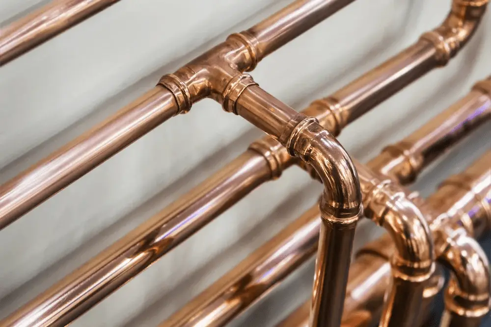
Fig. 1 below shows a typical example of a copper piping system:

Typical Copper Pipe System
Fig. 1: Typical Copper Pipe System

Copper Pipe Joining Methods

Copper pipes can be joined using various methods, each with its own set of advantages, applications, and considerations. The choice of joining method often depends on factors such as the type of copper pipe, the intended use, the level of expertise, and the specific requirements of the project. Here are some common copper pipe joining methods:

Soldering (Sweating):

Soldering is one of the most traditional and widely used methods for joining copper pipes. It involves heating the joint area with a propane torch and applying solder, a low-melting-point alloy, to create a watertight seal. This method requires skill and proper preparation to ensure a reliable connection. Soldering is commonly used for water supply lines, heating systems, and other non-pressurized applications.

Solder provides a quicker and less expensive joining solution for copper pipes and tubes than compression or flare fittings. The term sweating is also used to describe the process of soldering copper pipes. The filling material that is used for the joints of copper tubes usually has a melting point that is below 427 °C (800 °F).

Brazing:

Similar to soldering, brazing uses a higher-melting-point filler metal, often brass or another copper alloy, to create a strong joint. Brazing is typically employed in situations where higher strength and heat resistance are required, such as in HVAC systems or industrial applications. The filling material that is used for the copper pipe joints has a melting point of> 427 °C (800 °F ).

Compression Fittings:

Compression fittings consist of a nut and a ring (ferrule or olive) that compress around the copper pipe and create a seal when the nut is tightened. This method is relatively simple and doesn’t require heat or solder, making it suitable for DIY projects and situations where disassembly might be necessary.

Compression connections generally don’t provide the extended lifespan characteristic of sweat connections; however, they hold distinct benefits due to their simplicity of creation using fundamental tools. An inherent drawback of compression connections lies in their relatively longer setup time compared to sweat connections, occasionally necessitating periodic re-tightening to prevent leakage.

Push-Fit (Quick Connect) Fittings:

Push-fit fittings, Push-to-Connect, push-to-lock, or simply push fittings are designed for easy installation by simply pushing the copper pipe into the fitting. The fitting’s internal components create a secure connection without the need for solder or tools. These fittings are suitable for both copper and other types of pipes, offering convenience and versatility.

Flare Fittings:

Flare fittings are used with soft copper tubing and involve flaring the end of the tube and connecting it to a matching fitting. The joint is sealed using a flare nut and creates a secure connection, often used in gas lines, refrigeration systems, and air conditioning. Flare connections are a labor-intensive copper pipe joining method but are quite reliable.

Press Fittings:

Press fittings or crimped connections utilize a specialized tool to press a fitting onto the copper pipe, creating a watertight and secure connection. This method is efficient and reliable, making it popular in commercial and residential plumbing projects. They are basically special copper fittings that are permanently attached to rigid copper tubing with a manual or powered crimper. They are long-lasting.

Welding:

In specialized applications, such as industrial settings or large-diameter pipes, welding can be used to join copper pipes. This method involves melting the ends of the pipes and fusing them together.

Mechanical Joints:

Mechanical joints use devices like clamps or couplings to connect copper pipes without the need for soldering or other forms of heating. These joints are often used in underground or hard-to-reach areas.

Copper Pipe Sizes

Copper pipes come in various sizes, which are commonly referred to using two different measurements: the outside diameter (OD) and the nominal size. The nominal size is used to identify the pipe’s approximate inner diameter, while the outside diameter is the actual measurement of the pipe’s outer circumference. The following Table (Reference: https://en.wikipedia.org/) provides some of the common copper pipe sizes as per the U.S., Canadian, and Indian systems used for the plumbing industry.

Copper Tubing Sizes (CTS) for Plumbing
Nominal
size
Outside diameter
(OD)
[in (mm)]
Inside diameter (ID)
[in (mm)]
Type KType LType M
1438 (9.5)0.305 (7.747)0.315 (8.001)
3812 (12.7)0.402 (10.211)0.430 (10.922)0.450 (11.430)
1258 (15.875)0.528 (13.411)0.545 (13.843)0.569 (14.453)
5834 (19.05)0.652 (16.561)0.668 (16.967)0.690 (17.526)
3478 (22.225)0.745 (18.923)0.785 (19.939)0.811 (20.599)
11+18 (28.575)0.995 (25.273)1.025 (26.035)1.055 (26.797)
1141+38 (34.925)1.245 (31.623)1.265 (32.131)1.291 (32.791)
1121+58 (41.275)1.481 (37.617)1.505 (38.227)1.527 (38.786)
22+18 (53.975)1.959 (49.759)1.985 (50.419)2.009 (51.029)
2122+58 (66.675)2.435 (61.849)2.465 (62.611)2.495 (63.373)
33+18 (79.375)2.907 (73.838)2.945 (74.803)2.981 (75.717)
Table 1: Copper Pipe Sizes

In general, the most widely used standard copper pipe sizes range from ½ inch to 2 inches.

  • 1/2 inch (0.5 inches) Copper Pipe: One of the most versatile sizes, it’s used for a wide range of applications, including residential water supply lines, shower installations, and irrigation systems.
  • 3/4 inch (0.75 inches) Copper Pipe: Used for larger water supply lines, outdoor irrigation systems, and some larger appliances like washing machines.
  • 1 inch (1.0 inch) Copper Pipe: Typically used for main water supply lines, larger irrigation systems, and commercial plumbing applications.
  • 1 1/4 inch (1.25 inches), 1 1/2 inch (1.5 inches), 2 inches Copper Pipe: These larger sizes are used for industrial applications, larger plumbing systems, and areas requiring high water flow.

Copper Pipe Fittings

Copper pipe fittings are essential components used to connect and control the flow of copper pipes in various plumbing and HVAC systems. These fittings come in a wide range of shapes, sizes, and configurations, allowing for precise customization and adaptation to different applications. Here are some common types of copper pipe fittings:

  • Elbow Fittings: Elbow fittings are L-shaped connectors that allow pipes to change direction at a 90-degree or 45-degree angle. They are useful for navigating corners and obstacles in plumbing systems.
  • Tee Fittings: Tee fittings have a T-shape, allowing one main pipe to split into two branches at a 90-degree angle. They are often used to create connections for additional fixtures or pipes.
  • Coupling Fittings: Couplings are used to join two pipes of the same diameter in a straight line. They are helpful for extending pipe lengths or repairing sections of a copper pipe.
  • Reducer Fittings: Reducer fittings allow for a seamless transition between pipes of different sizes. They are useful when connecting pipes with varying diameters.
  • Union Fittings: Union fittings consist of two coupling halves joined by threads, allowing for easy disassembly and reassembly of pipes. They are handy in situations where pipes need to be disconnected for maintenance or repairs.
  • Adapter Fittings: Adapter fittings facilitate connections between pipes of different materials or sizes. They are useful for transitioning between copper and other types of pipes.
  • Cap and Plug Fittings: Cap fittings seal the end of a pipe, while plug fittings are used to close off openings in a fitting. They are employed to stop the flow or prevent debris from entering the system.
  • Flare Fittings: Flare fittings are used with soft copper tubing and involve flaring the end of the tube for a secure connection. They are common in gas lines and refrigeration systems.
  • Compression Fittings: Compression fittings include a nut and ferrule that compress around the pipe, creating a watertight seal when the nut is tightened. They are convenient for DIY projects and require no heat or soldering.
  • Push-Fit (Quick Connect) Fittings: Push-fit fittings allow pipes to be inserted into the fitting, creating a secure connection. These fittings are easy to install and require no tools or soldering.
  • Cross-Fittings: Cross fittings are shaped like a “+” and are used to create branching connections in plumbing systems, typically at 90-degree angles.
  • Valves: Valves control the flow of water or other fluids in a system. They can be used to start, stop, or regulate the flow and come in various types, including ball valves, gate valves, and globe valves.

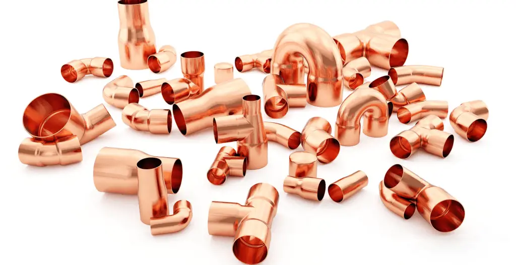
Fig. 2 below shows some typical copper pipe fittings.

Copper Pipe Fittings
Fig. 2: Copper Pipe Fittings

Advantages of Choosing Copper Pipes

  • Longevity: Copper pipes can last for decades, reducing the need for frequent replacements and maintenance.
  • Safety: The antimicrobial properties of copper pipes contribute to a cleaner and safer water supply.
  • Energy Efficiency: Their excellent heat conductivity supports energy-efficient heating and cooling systems.
  • Aesthetic Appeal: Copper pipes can add a touch of elegance to interior designs, especially in exposed piping layouts.
  • Sustainability: Copper is a recyclable material, making copper pipes and tubes an environmentally responsible choice.

Conclusion

Copper pipes and tubes have stood the test of time, proving their worth as indispensable components in various industries. Their blend of durability, versatility, and aesthetic appeal continues to make them a top choice for plumbers, engineers, and designers alike. As technology advances, copper pipes remain a symbol of the seamless integration of ancient wisdom and modern innovation in the world of construction and plumbing. Whether hidden behind walls or proudly displayed, copper pipes are more than just conduits—they’re a testament to the marriage of functionality and beauty.

What are Pipe Flange Protectors?

What is a Flange Protector?

Pipe Flange Protectors protect flange face, studs, and gaskets on the raised face, full face, and ring joint flanges from atmospheric corrosion encountered in chemical plants, onshore oil fields, metering stations, refineries, gas plants, offshore platforms, water and wastewater plants, pump stations, and underground pipelines. Controlling corrosion and awareness of its ever-damaging effects is paramount in piping and pipeline maintenance.

By using the Flange Protectors and Corrosion Inhibitor Grease, flanges are ensured to be safe from hazardous and unsightly corrosion that has huge potential to cause leakage, failure, or even shutdown of equipment.  The downtime, coupled with the cost of cutting and welding a new flange, and replacing flange bolts, nuts, and seals, becomes very expensive.

Typical Flange Protectors
Fig. 1: Typical Flange Protectors

Flange Protectors can even be used on cathodically isolated flanges to prevent foreign matter from shorting out or bridging over an isolating gasket. To ensure complete loading of flange cavities, All Flange Protectors are equipped with an exclusive positive loading relief vent and plug. The extruded, clear, flexible poly band allows visual inspection without removal of the protector and ensures complete filling of the flange cavity. Additionally, it is non-corroding provides many years of service life, and is reusable.

Benefits of Flange Protectors

Benefits of Flange Protectors include:

  • Envelopes flange and flange internals to prevent corrosion.
  • Maintains integrity of gasket and seal.
  • Keeps out moisture, chemicals, saltwater, debris, etc.
  • Ensures cathodic isolation protection by keeping the foreign matter out of the flange gap.
  • Quickly installed with a screwdriver.
  • Available for all size flanges.
  • Custom-engineered designs available per application
  • Highly Cost-effective
  • Can be removed and reused easily.

Materials for Flange Protectors

Flange Protectors can be made of various materials like:

  • Metallic Flange Protectors are made of Carbon Steel, Aluminum, Stainless Steel, Galvanized Steel, etc.
  • Non-metallic flange protectors are made of Polyethylene, LDPE, HDPE, Plywood, Sponge Rubber, etc.

Applications of Flange Protectors

The annular gap around the Flange Outer Diameter is highly vulnerable to debris and moisture ingression. These can result in gasket degradation and can cause corrosive damage to the flange, sealing faces, and studs. Excessive corrosion in such areas is hazardous, and replacement could lead to unscheduled downtime. To solve such problems, inexpensive and easy-to-fit range flange protectors are widely used.

Such flange protectors are tightened around a flange and packed with corrosion inhibitor grease. A build-up of pollutants from corrosive and salt-laden environments around the flange, gaskets, and studs is protected using these products. Because of these reasons, flange protectors are used in flanges of pressure vessels, heat exchangers, pipelines, and other process plants, where the ingress of moisture and debris is likely to degrade the mechanical efficiency or sealing integrity of the joint.

Material Handling Systems in Construction

Material handling systems mean the control of materials and products for project use in various stages starting from manufacturing, storage, distribution, consumption, and finally disposal. The system must ensure the safe handling of all project materials. In this process, the material handling system uses various manual, automatic, or semi-automatic equipment known as material handling equipment. So, the material handling system basically deals with the safety of material handling equipment & their operations.

Material Handling Systems are very important mechanisms in supply chain management as they efficiently manage material movement in a controlled way. The material handling operation varies between manufacturing, storage, construction, and transportation based on industry types.

The main objective of the material handling system is to ensure proper handling, lifting & offloading of equipment in order to ensure a safe workplace. It ensures the operations are in line with the required guidelines & project specifications. Debating with these standards and guidelines means tolerating the life of self and stakeholders. Basically, standard guidelines are followed in the construction of refineries, chemical & petrochemicals, pharmaceutical companies, and power plants.

Typical Material Handling Equipment
Fig. 1: Typical Material Handling Equipment

Advantages of Material Handling Systems

A properly designed material handling system helps a project in many ways like:

  • Proper resource allocation
  • Shorten delivery time
  • Forecasting
  • Proper Inventory control and management
  • Improved Production planning
  • Improved customer service and after-sales support and finally
  • Reduce overall material handling costs

That is the reason proper material handling systems are widely popular in all industries like chemical, aerospace, construction, automotive, pharmaceutical, manufacturing, oil and gas, petrochemical, paper, material processing, warehousing, distribution, etc.

Material Handling using an Overhead Crane
Fig. 2: Material Handling using an Overhead Crane

Components of a Material Handling System

There are various components that constitute a material handling system. It may vary significantly from project to project. Some of the widely used components are added below as a reference.

Cranes-

Cranes as material handling equipment are widely used for lifting and shifting equipment and materials. There are a variety of cranes (Fig. 2) available in the market. Some of those are from 5 MT TO 8000 MT. In the construction industry, basically, two types of cranes are being used nowadays.

  • tyre-mounted cranes and
  • crawler-mounted cranes.

Both can be used for lifting and shifting. The crawler-mounted cranes are used for high strength and they can move over Mud or difficult places. On the other hand, tyre-mounted cranes are used for clear surfaces, roads, or properly compacted places.

Slings & belt-

Sling and belt both are used to tie a piece of equipment. The number of slings and belts for a particular operation is decided based on load calculation. The formulae for load calculation are mentioned below for reference.

Load Calculation formula for slings and belts
Fig. 3: Load Calculation formula for slings and belts

Here, V1 is the load at point 1, V2 is the load at point 2 & W is the overall load.

D rings-

D rings are used to tie belts or slings with equipment or material to be lifted with cranes, prior to placing color code, specification & TPI (Third party inspection report needs to be ensured).

Eyebolts- 

These are the mechanical Bolts that are being used to fix and ensure that D rings and slings or belts have tied properly and are ready to lift. Lifting operations could be performed only after conforming to the inspector. The inspector or safety in charge shall ensure SWL (safe working loads), TPI reports, visual checking of color and threads, and SOPs.

Guiding rope-

After assembly, this one is vital to guide the load/ equipment to place at the foundation or workplace.  Because of the presence of air, the material can move here and there so a guiding rope shall be used to guide it under formal instruction. Traditionally 2 guiding ropes shall be used for proper erection, loading, or offloading.  The first rope will guide and the 2nd rope will resist the movement.

The other components that can form the material handling system are

  • Hoisting equipment
  • Monorails and workstation cranes
  • Conveyors
  • Casters and wheels
  • Automatic guided vehicles
  • Lift trucks
  • Automated storage and retrieval systems
  • Industrial robots, etc

In recent times, automation has been used in material handling systems which makes the material handling systems more efficient to perform their job.

Types of Material Handling Systems

Normally four types of material handling systems are used widely.

  • Storage Systems
  • Engineered Systems
  • Industrial Material Handling Trucks and
  • Bulk Material Handling Equipment

For maximum efficiency and safety, standardization of material handling methods, equipment, controls, and software should be used.

Pre-operation material handling system checklist

Use checklist to avoid mishap
Fig. 4: Use the material handling system checklist to avoid mishaps

As the operation is big and is being used by some of the biggest industries such as refineries, power plants, and aviation industries, a checklist should be followed to ensure safe operation. The following points must be ensured:

  • Crane operators, trailer operators, and rigging foremen should be competent with experience in using specified equipment.
  • All tools & tackles shall be TPI inspected.
  • The approved color code is being followed.
  • Lifting plans & JSA (Job safety analysis) should be in place.
  • All inspectors and supervisors should operate using the required PPES.
  • The workplace has to be inspected and compacted as per industry requirements.

Job Safety Analysis: Definition, Purpose, Requirements, Team Composition, Procedure, Sample Format

A Job Safety Analysis is a process to integrate health and safety principles into a particular job operation. In a job safety analysis (JSA), potential hazards for a specific job are identified before they occur and the safest way to perform the job is recommended. Such procedures reduce the risk of injury to working professionals and ensure that the workplace is compliant with safety regulations. Job safety analysis is also known as job hazard analysis (JHA) or job hazard breakdown and is an important step toward employee safety.

Advantages of Job Safety Analysis

The main purpose behind job safety analysis are:

  • Job-oriented risk assessment.
  • Identification and evaluation of hazards beforehand help in controlling the risk.
  • Control of incidents and thus minimization of loss.
  • Standardization through creating procedures and work instructions.
  • Ensuring safe working methods consistently.
  • Compliance with regulatory requirements (OSHA requirements)
  • Getting organized for doing the job right and efficiently.
  • Improving the work safety culture of the company.
  • Documentation of Job safety analysis fulfills audit requirements.
  • Increased productivity in absence of major hazards.
  • Improved quality of work.
  • Better planning in job execution and overall increased morale and profit.

Jobs requiring Job Safety Analysis

Job safety analysis is very important for all industries that face safety issues frequently. Typical industries that must include job safety analysis in their work culture are Oil and gas, construction, mining, power industries, electrical, etc. Working professionals from such industries should be constantly vigilant of potential hazard scenarios in the workplace. Even though all kinds of jobs irrespective of their type should be included in job safety analysis, companies can prepare a priority list as follows:

  • All jobs with the potential to cause fatality.
  • All jobs with the highest injury rates/ Fire and explosion incidents.
  • All jobs where human error can lead to severe accidents, fires, or explosions.
  • Jobs for which no prior work experience is present.
  • Jobs of complex nature.
  • Hot works inside the battery limit of operating plants.
  • The major modification works.
  • Jobs that include health and ergonomic issues.

Job safety analysis can be excluded only for routine non-critical jobs without the potential to hazard development. Normally, the Sectional Head / Area in-charge/ Plant Engineers/ or Managers will be responsible to carry out Job Safety Analysis of all activities in respective units. The management of any organization must demonstrate its commitment to safety and health for a job hazard analysis to be effective and should take necessary steps to correct identified hazards.

Job Safety Analysis team composition

The Job Hazard Analysis is normally carried out by forming a team comprising of;

  • Person/Team who does the work
  • A person supervising the job
  • A person with safety knowledge
  • Person (Specialist/Consultant) with technical knowledge
  • Area in-charge
  • Area maintenance and operation engineer

Depending on the complexity of the job, the number of team members can vary.

Job Safety Analysis Procedure

The Job Safety Analysis Procedure for any job consists of the following 7 steps:

  • Step 1: Select the job for job safety analysis and survey the job based on the site condition.
  • Step 2: Break down and describe the sequence of job steps
  • Step 3: Identification and assessment of the potential hazards and risks of each step
  • Step 4: Description of the recommended safe job procedure against each step.
  • Step 5: Identification of what might go wrong and backup controls.
  • Step 6: Review of the Job safety analysis documentation, approval, and checking compliance at the working site.

How to Assess Hazards for Job Safety Analysis

To identify hazards for job safety analysis, brainstorming is required for each step of the job. The previous history of similar jobs, employee complaints, etc must be studied. The following questions can be asked for hazard finding:

  • What can go wrong?
  • What could be the possible consequences?
  • How it could happen?
  • What are the contributing factors?
  • What is the probability of the hazard occurring?
  • What safety measures are in place right now?

Probable Steps for Hazard Elimination in Job Safety Analysis

The following steps are normally followed in job safety analysis for hazard elimination

  • Eliminate the hazard where possible
  • Substitute the hazard
  • Isolate the hazard
  • Use of Engineering Controls to prevent the hazard
  • Use of administrative controls
  • Use of personal protective equipment.

Sample Job Safety Analysis Format

The image in Fig. 1 presents a sample job safety analysis format for reference purposes.

Job Safety Analysis Sample Format
Fig. 1: Job Safety Analysis Sample Format

Improvements in Job Safety Analysis

The manual method of job safety analysis costs time from ongoing projects. So a balance for safety with less time must be achieved by improving the efficiency of the job safety analysis process. A number of steps as mentioned below can be considered for improvement:

  • Standardization of the process by organizing the required steps.
  • Digitization of the job safety analysis process. In recent times various software applications are available for performing job safety analysis.

Online Safety Courses

To explore more about safety, the following online courses will help you. Kindly click on the subject, review the course and then enroll for it if interested:

References and Further Studies

Detailed guidelines for job safety analysis procedure and steps can be found by accessing the following pdf document by OSHA: osha3071.pdf

Technical Aspects Of Equipment Procurement

What is Equipment Procurement for Process Plants?

Various equipment is required for any chemical, petrochemical, oil & gas projects. So, this equipment must be procured. In any process industry, Equipment procurement is a long process. So proper equipment procurement planning is required. The process, in general, involves the following steps:

  • The Demand for the Equipment Purchase is raised by the Technical Department (Mostly Process Department)
  • MR i.e, Material Requisition Preparation by the Purchase Department with the help of the technical department (It includes all terms and conditions, design standards and specifications, delivery terms, Warranty, etc.)
  • Thorough Supplier Research and Shortlisting by the Procurement Department.
  • Value Analysis (Technical Bid Evaluation and Technical Query Resolution) by Process and Mechanical Department.
  • Price Negotiation and Financing by the Purchase Department
  • Selecting the Final Vendor by Purchase Department
  • Proceeding for the Purchase
  • Inspection and Testing of the Equipment
  • Administration of Supply Contract terms
  • Receiving the Equipment at the Construction Site

Regarding the equipment procurement process, one important thing to consider is that this activity is different based on the geographical location of the processing unit.  Depending on whether this is being done in North America, the Middle East, Africa, the European Union, Asia-Pacific, or South Asia, the equipment procurement has its own individual characteristics. This article will provide below listed 8 important ideas related to the technical aspects of equipment procurement.

Approved Vendor List for Equipment Procurement

It is always preferable to make an “Approved Vendor List” by the Client or the EPC contractor. This list will reduce the time required for supplier research completely. While floating an inquiry, the procurement personnel is bound by this list without the need to look further beyond this list. Having an approved vendor list makes the procurement activity simpler.

Trimming/Shortlisting the Approved Vendor List

Now it could so happen that for a piece of particular equipment, there are many vendors in the approved vendor list. Normally, most of the client companies have a registration process for being an approved vendor for the company. And it is quite natural that all the manufacturers will try to include their names in the “Approved Vendor List” list which causes the list to be too big with numerous vendors.

Hence, Floating an inquiry for a piece of particular equipment to all the listed for that equipment is not a practical thing to do. In such a situation, An experienced purchase professional should trim the list of these vendors based on his knowledge of the vendor’s capabilities and restrict his inquiry to a top few vendors. It is preferable to restrict floating an inquiry to 4 to 5 vendors.

Fast-Tracking of Long-Lead Items

Long lead items can be referred to as equipment, products, or systems that have a delivery time long enough to directly influence the overall lead time of the project during the EPC phase.

An experienced equipment procurement engineer must identify all such equipment at the earliest stage of a project and ensure that the inquiries are fast-tracked. Generally, various organizations have their own terms to decide long-lead items depending on the type of plant being installed. As a rule of thumb, any item with a lead time of more than 8 calendar months can be considered a long lead in today’s perspective of fast-tracked plants.

Typical Pressure Vessel for a Process Plant

Raising Technical Query (TQ) and Resolution for the equipment

In terms of the submission of offers as per the inquiry, efficient procurement personnel should continuously keep track of the responses provided by each vendor. He or she must be familiar with the process of raising “Technical Queries”, popularly known as “TQ” on the offers provided by the vendors. Most companies have a standard TQ format for various types of standard equipment.

Most of the time, individual engineering disciplines raise the TQs in their own TQ formats. The procurement engineer must collate all this information in one document for the sake of clarity and final documentation.

Across the table, Clarification Meetings to Resolve issues

Equipment Information normally flows via e-mails with attachments and occasional telephonic conversation and video conferencing.  However, it is always preferable to arrange face-to-face (across-the-table) communication (discussion) with vendors. The unanswered questions and issues are resolved best when you are sitting across the table and discussing them.

Some good procurement engineers prefer to follow this very principle. Obviously, an advance discussion agenda must be provided to the party with whom you want the discussion to happen to make the meeting more fruitful.

Technical Bid Evaluation (TBE)

Based on TQ resolution, when the offers from the vendors are streamlined to match the project requirements the “Technical Bid Analysis (/Evaluation)” abbreviated as “TBA (/or TBE)” is conducted by the engineering design disciplines with active support and follow-up from the procurement engineer.

Most of the reputed/established engineering companies have their standard TBA formats for standard process plant equipment. The purpose of the TBA is to compare the offers of the vendors in the race for bagging the equipment order strictly from a technical viewpoint.  The standard TBA worksheet has the benchmarking parameters of the particular equipment in the first column of the worksheet and the subsequent columns are information provided by the vendors against those benchmarked parameters.

For example, if you have 4 vendors for the same equipment there will be 4 columns in the worksheet for filling in the data provided by the vendors against the selected pre-decided parameters. A summary section provided in the worksheet will rate each vendor’s overall technical capabilities and provide rankings and in some cases, even reject one or more of the vendors.

Commercial Negotiation of the Equipment Order

Commercial negotiations for the equipment order will be the next step of the procurement cycle.  For example, if four vendors have submitted offers and the TBE concludes that all four are equal in their technical capabilities then by simple logic, the vendor offering the lowest cost of the equipment will be selected. Note that this may not always be true as a few other factors like market reputation, past association with the company, and other extraneous factors may take precedence in the selection of the vendor.

Purchase Order Specification

The last step from a technical viewpoint in the procurement cycle is to place the order of the equipment to the selected vendor in the form of a proper “Purchase Order” (PO) specification or requisition along with the commercial terms and conditions of purchase. The PO specification would generally include some technical data and information specific to the selected vendor’s evaluated and accepted offer.

However, The aforementioned steps do not end the procurement cycle or the responsibility of the procurement engineer. The logistics of equipment procurement now come into the forefront including items such as stage-wise inspection, factory acceptance test, test certification, packing, shipping, warehouse storage, insurance, and demurrage.

Hot Rolled vs Cold Rolled Steel: What are the differences?

As per the World Steel Association, there are over 3,500 different steel grades with unique properties available. The manufacturing processes of steel contribute significantly towards the properties of the final product. Hot rolling and cold rolling are two such processes of steel that affect the overall performance and application. In this article, we will discuss, the main differences between hot-rolled and cold-rolled steel.

What is Hot Rolled Steel?

Hot-rolled steel is produced by rolling the steel at temperatures above the steel’s recrystallization temperature (>1700° F.). Heating the steel above the recrystallization temperature makes the steel easier to shape and form, and the steel can be produced in much larger sizes. For products where tight tolerances are not required, hot-rolled steel is ideal.

The manufacturing of hot rolled steel starts with heating a large billet. Next, it is sent for pre-processing and the billet turns into a large roll. The final dimension is achieved by running it through a series of rollers at high temperatures. For sheet metal, hot rolled steel is spun into coils and left to cool. For other forms like bars or plates, materials are sectioned and packaged for despatch.

What is Cold Rolled Steel?

Cold-rolled steel is produced in cold reduction mills by processing the hot-rolled steel after cooling it to room temperature. Cold-rolled steels can be produced with tighter dimensional tolerances and a wide range of surface finishes.

Differences between Hot Rolled and Cold Rolled Steel

Let’s find out the main differences between hot-rolled and cold-rolled steel.

Differences between hot rolled and cold rolled steel
Differences between hot-rolled and cold-rolled steel

Hot Rolled vs Cold Rolled Steel: Mechanical Properties

Cold-rolled steel members normally have around a 20% increase in mechanical strength because of strain hardening. The hardness value also increases while making cold-rolled steel from hot-rolled steel due to cold forming. So cold-rolled steel members are stronger and harder than hot-rolled steel members. As the metal is shaped at lower temperatures, due to the work hardening effect, the cold rolled steel’s hardness, resistance against tension breaking, and deformation are all increased.

Depending on the grade of the steel the mechanical properties vary. In the following table, a comparison of common mechanical properties for hot-rolled and cold-rolled steel grade 1018 is provided to get a feel of the mechanical property changes.

Mechanical PropertiesHot RolledCold Rolled% change
Tensile Strength67,000 psi85,000 psi26.9
Yield Strength45,000 psi70,000 psi55.6
Reduction of Area5855-5.2
Elongation in 2″3628-22.2
Brinell Hardness13716718.0
Table 1: Hot Rolled vs Cold Rolled Steel – Mechanical Properties

Hot Rolled vs Cold Rolled Steel: Manufacturing, Cost

Hot-rolled steel manufacturing is done above recrystallization temperature whereas cold-rolled steel involves much lower temperatures, generally room temperature.

As the metal is hot in hot rolled steel, it needs less force and energy to shape it. But the force and energy required to shape a cold rolled product is more.

Hot-rolled steel is easier to make. Cold-rolled steel involves further processing steps that increase the manufacturing steps as well as time requirements. So, overall the cost of cold-rolled steel is much higher than hot-rolled steel of the same grade.

Hot Rolled vs Cold Rolled Steel: Surface characteristics

Hot rolled steel is characterized by a scaly surface, slightly rounded corners, and edges and the surface is not smooth and non-oily. On the contrary, cold rolled steel comes with an oily or greasy finish, a very smooth surface, and very sharp edges. The concentricity and straightness of cold-rolled steel are better when compared to hot-rolled.

Hot Rolled vs Cold Rolled Steel: Dimensional Tolerances

Cold-rolled steel can produce tighter tolerances for products as compared to hot-rolled steel. A more consistent and accurate shape is the feature of cold-rolled steel. For bars, they produce true and square sections. Pipes and tubes of uniform concentricity and straightness are produced using cold-rolled steel.

On the other hand, due to shrinkage during cooling dimensional imperfections exist in hot-rolled steel.

Hot Rolled vs Cold Rolled Steel: Applications

Most popular commercially available shapes are made from hot-rolled steel. All structural members like UC, UB, RSA, PFC, etc, and blooms, billets, sheets, slabs, tubes, bars, etc are hot rolled. On the contrary, only fewer specific shapes like Sheets, box section shapes (CHS, SHS, RHS), and round shapes are made from cold rolled steel.

Hot rolled steels are widely used as structural beams, railroad tracks, sheet metal, automotive frames, agricultural equipment, etc. Cold-rolled steel finds its application in bars, rods, strips, pipes, metal furniture, aerospace structures, hole appliances, roof, and wall systems.

Hot Rolled vs Cold Rolled Steel: Disadvantages

Poor surface finish, lower hardness, and strength are the only concerns for hot rolled steel. Cold work treatments in cold rolled steel can create internal stresses and unpredictable warping.