Recent Posts

A Comprehensive Guide to Non-Metallic Pipes

Non-metallic pipes have become increasingly significant in various industries due to their unique properties and advantages over traditional metallic pipes. These pipes, which can be made from materials such as plastic, fiberglass, and composites, offer a range of benefits including corrosion resistance, light weight, and cost-effectiveness. This article explores the types of non-metallic pipes, their applications, advantages, and future trends, providing a comprehensive understanding of this crucial component in modern infrastructure.

1. Introduction to Non-Metallic Pipes

Non-metallic pipes are pipes made from materials that do not include metals. Instead, they are crafted from synthetic polymers, ceramics, glass, or composite materials. They are widely used in various applications, from residential plumbing to industrial processes, due to their distinctive properties that cater to specific needs and environments.

1.1 Definition and Types

Non-metallic pipes are characterized by their composition and properties, differing significantly from metallic pipes in terms of physical characteristics and performance. Common types include:

  • Plastic Pipes: Made from polymeric materials like PVC (Polyvinyl Chloride), CPVC (Chlorinated Polyvinyl Chloride), and PEX (Cross-linked Polyethylene).
  • Fiberglass Pipes: Composed of glass fibers and resin, providing high strength and durability.
  • Composite Pipes: Constructed from a combination of materials, such as fiberglass and thermoplastics, to leverage the benefits of both.
Non-Metallic Pipes
Fig. 1: Non-Metallic Pipes

2. Advantages of Non-Metallic Pipes

Non-metallic pipes offer several advantages that make them suitable for a variety of applications. Here, we delve into some of the primary benefits:

2.1 Corrosion Resistance

Unlike metals, many non-metallic pipes are highly resistant to corrosion and chemical degradation. This property is particularly beneficial in environments where pipes are exposed to harsh chemicals or moisture. For instance:

  • PVC and CPVC Pipes: Resistant to many acids, alkalis, and salts, making them ideal for chemical processing.
  • Fiberglass Pipes: Corrosion-resistant and suitable for handling corrosive fluids in industrial settings.

2.2 Lightweight and Easy to Handle

Non-metallic pipes are typically much lighter than their metallic counterparts. This reduces transportation and installation costs and simplifies handling on site. The lightweight nature of these pipes also leads to less strain on supporting structures and lower installation labor costs.

2.3 Flexibility and Ease of Installation

Materials like PEX offer flexibility, allowing for easier installation, especially in tight spaces or complex layouts. Non-metallic pipes often do not require special tools or welding, which speeds up the installation process.

2.4 Insulation Properties

Many non-metallic pipes have excellent thermal insulation properties, reducing heat loss in hot water systems and preventing condensation in cold water systems. This can contribute to energy savings and improved efficiency in various applications.

2.5 Cost-Effectiveness

In many cases, non-metallic pipes are more cost-effective than their metallic counterparts. The lower material and installation costs can be particularly advantageous for large-scale projects or applications where budget constraints are significant.

3. Types of Non-Metallic Pipes

Depending on the exact non-metallic pipe material used for manufacture of the pipe, there are several types of non-metallic pipes.

3.1 Plastic Pipes

Plastic pipes are among the most commonly used non-metallic pipes, encompassing various types and grades.

3.1.1 Polyvinyl Chloride (PVC) Pipes

PVC pipes are widely used due to their versatility, affordability, and ease of installation. They are commonly used in residential and commercial plumbing, irrigation, and drainage systems. Key characteristics include:

  • Durability: Resistant to impact and wear.
  • Corrosion Resistance: Not susceptible to rust or corrosion.
  • Low Cost: Economical compared to metals.

3.1.2 Chlorinated Polyvinyl Chloride (CPVC) Pipes

CPVC pipes are similar to PVC but with added chlorine, making them suitable for hot water applications. They are often used in domestic hot and cold water systems and industrial processes.

  • Temperature Resistance: Can handle temperatures up to 200°F (93°C).
  • Chemical Resistance: Effective in handling various chemicals.

3.1.3 Cross-Linked Polyethylene (PEX) Pipes

PEX pipes are known for their flexibility and resistance to temperature extremes. They are widely used in residential plumbing and heating systems.

  • Flexibility: Can be bent around obstacles without the need for joints.
  • Freeze Resistance: Less likely to burst if water inside freezes.

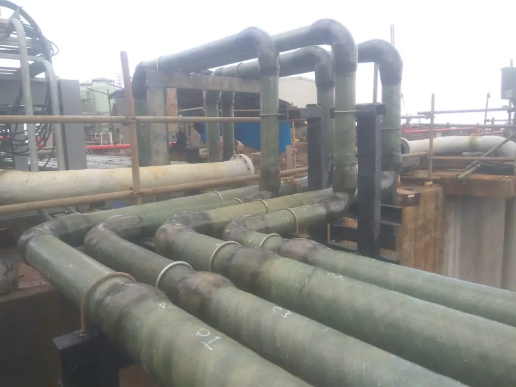
3.2 Fiberglass Pipes

Fiberglass pipes are made from a combination of glass fibers and resin. They are particularly valued in industries requiring high strength and resistance to chemical attack.

  • Strength: High tensile strength and impact resistance.
  • Lightweight: Easier to handle and install compared to metals.

3.3 Composite Pipes

Composite pipes combine various materials to optimize performance. Common composites include fiberglass-reinforced plastic (FRP) and carbon fiber-reinforced plastic (CFRP).

  • High Performance: Offer enhanced strength-to-weight ratios.
  • Customization: Tailored to specific applications and environmental conditions.

3.4 Miscellaneous Non-Metallic Pipes

The above non-metallic pipes are the most common pipe materials. Additional to these, the following pipes are also found in some applications of non-metallic pipes:

3.4.1 Clay Pipes

Clay pipes, traditionally made from fired clay, have been used for centuries in various applications, particularly in drainage and sewer systems. Their natural durability and resistance to corrosion make them suitable for handling wastewater and sewage, as well as for agricultural drainage. Clay pipes are still employed in some modern applications, especially in restoration projects and where historical authenticity is required. They are valued for their long service life and resistance to environmental degradation, although their brittle nature and relatively high installation costs have led to a decline in their use in favor of more modern materials.

3.4.2 Concrete Pipes

Concrete pipes are widely used in infrastructure projects due to their strength and durability. They are commonly utilized in stormwater drainage systems, sewerage, and water supply networks. The inherent compressive strength of concrete makes these pipes suitable for handling high-pressure applications and heavy loads. Reinforced concrete pipes (RCP), which incorporate steel reinforcement, are particularly effective for high-stress environments. Concrete pipes are valued for their longevity and load-bearing capacity, but their heavy weight can pose challenges during installation and transportation. Advances in concrete technology, including the use of fiber reinforcement, have further enhanced their performance and versatility.

3.4.3 Wood Pipes

Wood pipes, though less common today, were historically used for water transportation and irrigation. Made from hollowed-out tree trunks or logs, they provided a practical solution in pre-industrial times. Wooden pipes were used in ancient aqueducts and early plumbing systems, leveraging the natural availability of wood. Despite their historical significance, wood pipes are rarely used in modern applications due to their susceptibility to decay, limited lifespan, and challenges related to maintaining a consistent flow and pressure. However, they are sometimes employed in niche applications, such as in the restoration of historic sites or for aesthetic purposes in specialized landscaping projects.

3.4.4 Glass Pipes

Glass pipes are utilized in specific applications where their unique properties are advantageous. They are commonly found in laboratory settings, where their inertness and clarity make them ideal for handling chemicals and monitoring fluid flow. Glass pipes offer excellent resistance to corrosion and are easy to clean, which is crucial for maintaining the integrity of experiments and processes. Additionally, their smooth interior surfaces minimize friction loss, enhancing flow efficiency. In architectural and design applications, glass pipes can be used for aesthetic purposes, adding a modern and visually appealing element to installations. Despite their benefits, the fragility of glass and the higher cost compared to other materials limit their use to specialized applications.

Non-metallic Pipes in Industrial Applications
Fig. 2: Non-metallic Pipes in Industrial Applications

4. Applications of Non-Metallic Pipes

The versatility of non-metallic pipes means they are used in a wide range of applications. Here are some notable uses:

4.1 Residential Plumbing

Non-metallic pipes like PVC and PEX are commonly used in residential plumbing systems due to their ease of installation and resistance to corrosion.

  • Water Supply: PEX and CPVC are often used for water supply lines.
  • Drainage: PVC is widely used for drainage and waste pipes.

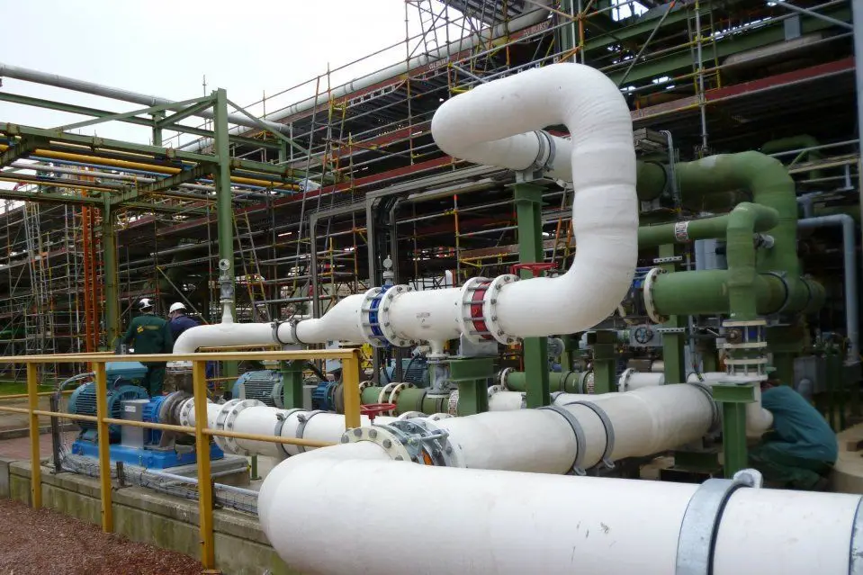
4.2 Industrial Applications

In industrial settings, non-metallic pipes are used for handling chemicals, gases, and other substances.

  • Chemical Processing: CPVC and fiberglass pipes are used to transport corrosive chemicals.
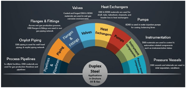
  • Oil and Gas: Composite pipes are used in some oil and gas applications due to their strength and resistance to harsh conditions.

4.3 Irrigation Systems

Plastic pipes like PVC and polyethylene are frequently used in agricultural irrigation systems due to their durability and resistance to environmental factors.

  • Drip Irrigation: PVC and polyethylene pipes are used for drip irrigation systems that deliver water directly to the plant roots.
  • Sprinkler Systems: Plastic pipes are also used in various types of sprinkler systems.

4.4 HVAC Systems

Non-metallic pipes are used in heating, ventilation, and air conditioning (HVAC) systems for their thermal insulation properties and flexibility.

  • Ventilation: PVC and fiberglass pipes are used in ductwork for ventilation systems.
  • Heating: PEX is commonly used in radiant heating systems due to its flexibility and thermal efficiency.

5. Challenges and Considerations

While non-metallic pipes offer many advantages, they also come with their own set of challenges and considerations.

5.1 Temperature Limitations

Some non-metallic pipes have limitations regarding temperature. For example, while PEX is flexible and freeze-resistant, it may not be suitable for extremely high-temperature applications. Understanding the temperature tolerance of each pipe type is crucial for ensuring optimal performance.

5.2 Mechanical Strength

Non-metallic pipes, particularly plastics, may have lower mechanical strength compared to metals. This can be a concern in high-pressure applications or where mechanical impact is a factor. Composite pipes often address this limitation by combining materials to enhance strength.

5.3 Environmental Impact

The production and disposal of non-metallic pipes, especially plastics, can have environmental impacts. Efforts are being made to improve the sustainability of these materials, such as through recycling programs and the development of biodegradable alternatives.

5.4 Installation and Compatibility

While non-metallic pipes can be easier to install, compatibility with existing systems and materials is an important consideration. Proper installation practices are essential to avoid issues like leaks or joint failures.

6. Non-Metallic Piping Standards

The codes and standards for non-metallic pipes ensure that these materials meet specific requirements for quality, safety, and performance. These standards are developed by various organizations and provide guidelines for manufacturing, testing, and application of non-metallic piping systems. Below is an overview of some key codes and standards for different types of non-metallic pipes:

6.1 Plastic Pipes

6.1.1 Polyvinyl Chloride (PVC) Pipes

  • ASTM D1785: Standard Specification for PVC Pipe, Schedules 40, 80, and 120
    • Covers the requirements for PVC pipe used in pressure systems.
  • ASTM D2665: Standard Specification for PVC Plastic Drain, Waste, and Vent Pipe and Fittings
    • Addresses specifications for PVC pipes used in non-pressure applications.
  • ASTM D2846: Standard Specification for Chlorinated Polyvinyl Chloride (CPVC) Pipe, Schedules 40, 80, and 120
    • Provides specifications for CPVC pipes, including those used for hot water systems.
  • ASTM F441: Standard Specification for CPVC Plastic Pipe and Fittings
    • Covers the requirements for CPVC pipe and fittings for various applications.

6.1.2 Cross-Linked Polyethylene (PEX) Pipes

  • ASTM F876: Standard Specification for Cross-Linked Polyethylene (PEX) Tubing
    • Specifies the requirements for PEX tubing, including material properties, dimensions, and performance.
  • ASTM F877: Standard Specification for PEX Plastic Hot- and Cold-Water Distribution Systems
    • Covers the requirements for PEX systems used in hot and cold water distribution.
  • ASTM F1960: Standard Specification for PEX Plastic Hot- and Cold-Water Distribution Systems
    • Details the performance characteristics of PEX fittings used with PEX tubing.

6.2 Fiberglass Pipes

  • ASTM D2996: Standard Specification for Filament-Wound Fiber-Reinforced Thermosetting Resin Pipe
    • Provides specifications for filament-wound fiberglass pipes used in various industrial applications.
  • ASTM D3517: Standard Specification for Glass-Fiber-Reinforced Plastic (GRP) Pipe
    • Outlines requirements for GRP pipes, including material composition, dimensions, and performance.
  • ASME RTP-1: Reinforced Thermoset Plastic Corrosion-Resistant Equipment and Piping
    • Offers guidelines for the design, materials, and testing of reinforced thermoset plastic pipes, including fiberglass.

6.3 Composite Pipes

  • ASTM D1998: Standard Specification for Polyethylene (PE) Plastic Pipe (DR-PR) Based on Outside Diameter
    • Covers requirements for composite pipes that include polyethylene as one of their components.
  • ASTM D3694: Standard Specification for Reinforced Thermosetting Resin (RTR) Pipe
    • Provides guidelines for RTR pipes, which may include composite materials such as fiberglass.
  • ISO 14692: Petroleum and natural gas industries — Glass-reinforced plastics (GRP) piping
    • Specifies the requirements for GRP piping systems used in the oil and gas industry.

6.4 General Codes and Standards

  • ISO 9001: Quality management systems – Requirements
    • Although not specific to non-metallic pipes, compliance with ISO 9001 can ensure that the manufacturing processes meet quality management standards.
  • NFPA 13: Standard for the Installation of Sprinkler Systems
    • Provides guidelines that may include the use of non-metallic pipes for sprinkler systems.
  • ASME B31.3: Process Piping
    • Includes specifications that may apply to non-metallic pipes used in process piping systems.

6.5 Installation and Testing Standards

  • ASTM F1960: Standard Specification for PEX Plastic Hot- and Cold-Water Distribution Systems
    • Includes installation guidelines for PEX systems.
  • ASTM F2023: Standard Guide for the Installation of PEX Systems
    • Provides recommendations and best practices for installing PEX piping systems.
  • ASTM D2152: Standard Test Methods for the Evaluation of the Effects of a Specific Chemical Environment on the Tensile Properties of Plastics
    • Details testing methods for evaluating how chemicals affect plastic pipes.

6.6 Environmental and Safety Standards

  • ASTM D3350: Standard Specification for Polyethylene Plastics Pipe and Fittings Materials
    • Specifies environmental and safety considerations for polyethylene pipes.
  • ISO 14001: Environmental Management Systems
    • Although not specific to non-metallic pipes, compliance with ISO 14001 can help manage environmental impacts related to the production and disposal of pipes.

7. Differences Between Non-Metallic and Metallic Piping

When selecting piping materials for various applications, understanding the differences between non-metallic and metallic pipes is crucial. Both types have distinct properties that make them suitable for specific conditions and uses. Here’s a comprehensive comparison of non-metallic and metallic piping systems across several key aspects:

7.1 Material Composition

Non-Metallic Pipes

  • Plastic: Includes materials such as Polyvinyl Chloride (PVC), Chlorinated Polyvinyl Chloride (CPVC), and Cross-Linked Polyethylene (PEX).
  • Fiberglass: Composed of glass fibers embedded in resin.
  • Composites: Made from a combination of materials, such as fiberglass and thermoplastics.

Metallic Pipes

  • Steel: Includes Carbon Steel, Stainless Steel, and Alloy Steel.
  • Copper: Used in plumbing and refrigeration systems.
  • Aluminum: Lightweight and resistant to corrosion, used in various applications.

7.2 Mechanical Properties

Non-Metallic Pipes

  • Flexibility: Generally more flexible, especially PEX pipes, which can bend around obstacles without fittings.
  • Strength: While non-metallic pipes are strong, they typically have lower tensile and impact strength compared to metals. Composite pipes can offer enhanced strength.
  • Weight: Much lighter than metallic pipes, easing handling and installation.

Metallic Pipes

  • Strength: High tensile and impact strength, making them suitable for high-pressure and heavy-duty applications.
  • Weight: Heavier, which can increase transportation and installation costs.

7.3 Corrosion and Chemical Resistance

Non-Metallic Pipes

  • Corrosion Resistance: Highly resistant to corrosion and chemical degradation. PVC, CPVC, and PEX are not susceptible to rust.
  • Chemical Resistance: Various non-metallic pipes are resistant to specific chemicals, though this varies by material. For example, CPVC handles a wider range of chemicals compared to PVC.

Metallic Pipes

  • Corrosion Resistance: Susceptible to rust and corrosion unless treated or alloyed. Stainless steel offers better resistance compared to carbon steel.
  • Chemical Resistance: Metal pipes, especially those made from alloyed or coated materials, can resist certain chemicals but often require protective linings or coatings.

7.4 Temperature Tolerance

Non-Metallic Pipes

  • Temperature Range: Generally have lower temperature tolerance. PEX can handle temperatures up to about 200°F (93°C), while CPVC can handle higher temperatures.
  • Thermal Insulation: Often have better natural thermal insulation properties compared to metals.

Metallic Pipes

  • Temperature Range: Can handle higher temperatures. For example, steel pipes can withstand temperatures above 1000°F (537°C) when properly treated.
  • Thermal Conductivity: Metals conduct heat more effectively, which can lead to heat loss or gain unless properly insulated.

7.5 Installation and Maintenance

Non-Metallic Pipes

  • Installation: Typically easier and quicker to install. Many non-metallic pipes can be cut and assembled with simple tools, and PEX does not require joints in most applications.
  • Maintenance: Generally low-maintenance due to resistance to corrosion and scale buildup. However, some non-metallic pipes can be damaged by UV exposure and may require protection.

Metallic Pipes

  • Installation: Can be more complex and require welding or threaded connections. Heavyweight can also complicate handling and installation.
  • Maintenance: May require regular inspection and maintenance to prevent rust and corrosion. Metal pipes can accumulate scale and require cleaning or replacement in high-sediment areas.

7.6 Cost

Non-Metallic Pipes

  • Material Cost: Usually lower than metals, making them cost-effective for large-scale or low-budget projects.
  • Installation Cost: Generally lower due to ease of handling and fewer required fittings.

Metallic Pipes

  • Material Cost: Typically higher, especially for materials like stainless steel and copper.
  • Installation Cost: Higher due to the need for specialized tools and labor, such as welding or threading.

7.7 Environmental Impact

Non-Metallic Pipes

  • Production: Production processes for plastics and composites can be energy-intensive and have environmental impacts. However, advancements in recycling and biodegradable materials are addressing these concerns.
  • End-of-Life: Non-metallic pipes can be challenging to recycle, though efforts are being made to improve recycling processes.

Metallic Pipes

  • Production: Metal pipe production also has significant environmental impacts, including energy use and emissions. However, metals are generally more recyclable than plastics.
  • End-of-Life: Metals are often more easily recycled, which can mitigate some of the environmental impact.

7.8 Applications

Non-Metallic Pipes

  • Residential Plumbing: PVC, CPVC, and PEX are commonly used for water supply and drainage in homes.
  • Chemical Processing: CPVC and fiberglass are used due to their resistance to corrosive substances.
  • Irrigation: PVC and polyethylene pipes are widely used in agricultural irrigation systems.

Metallic Pipes

  • Industrial Applications: Steel and stainless steel are used in high-pressure and high-temperature environments, such as in oil and gas pipelines.
  • Plumbing and Heating: Copper pipes are used in plumbing and heating systems due to their thermal conductivity and antibacterial properties.
  • Structural Applications: Metals are used where high strength and load-bearing capacity are required.

The above differences between non-metallic and metallic pipes can be summarized as follows:

AspectNon-Metallic PipesMetallic Pipes
Material Composition– Plastic (PVC, CPVC, PEX)
– Fiberglass
– Composites (e.g., FRP)
– Steel (Carbon, Stainless, Alloy)
– Copper
– Aluminum
Mechanical PropertiesFlexibility: Generally more flexible
Strength: Lower tensile and impact strength compared to metals; composites improve strength
Weight: Lighter
Flexibility: Less flexible
Strength: High tensile and impact strength
Weight: Heavier
Corrosion & Chemical ResistanceCorrosion: Highly resistant to corrosion
Chemical Resistance: Good, but varies by material (e.g., CPVC better for chemicals than PVC)
Corrosion: Susceptible to rust; stainless steel more resistant
Chemical Resistance: Varies; metals often need coatings or linings
Temperature ToleranceRange: Lower temperature tolerance (e.g., PEX up to 200°F/93°C)
Thermal Insulation: Better natural insulation properties
Range: Higher temperature tolerance (e.g., steel above 1000°F/537°C)
Thermal Conductivity: Higher, which can lead to heat loss/gain
Installation & MaintenanceInstallation: Easier and quicker; often requires fewer tools
Maintenance: Low maintenance; resistant to corrosion and scale buildup but can be UV-sensitive
Installation: More complex; often requires welding or threading
Maintenance: Higher maintenance; prone to rust, corrosion, and scale buildup
CostMaterial Cost: Generally lower
Installation Cost: Lower due to ease of handling
Material Cost: Generally higher
Installation Cost: Higher due to complexity and weight
Environmental ImpactProduction: Can be energy-intensive; recycling efforts underway
End-of-Life: Recycling can be challenging
Production: Significant environmental impact, but metals are recyclable
End-of-Life: Easier to recycle
ApplicationsResidential Plumbing: PVC, CPVC, PEX for water supply and drainage
Chemical Processing: CPVC, fiberglass for corrosive substances
Irrigation: PVC, polyethylene
Industrial Applications: Steel, stainless steel for high-pressure/high-temperature uses
Plumbing and Heating: Copper for plumbing and heating
Structural: Metals for load-bearing applications
Table 1: Metallic vs Non-Metallic Pipes

8. Conclusion

Non-metallic pipes offer a range of benefits that make them suitable for a diverse array of applications. Their advantages in terms of corrosion resistance, lightweight nature, and cost-effectiveness position them as valuable alternatives to traditional metallic pipes. As technology advances and environmental considerations become more prominent, the development and use of non-metallic pipes are expected to evolve, continuing to meet the needs of various industries while addressing sustainability challenges.

What is a Pipe Spool and Why is it Important?

A pipe spool is a prefabricated, smaller segment of piping that is assembled and tested in a workshop before being delivered to the construction site for installation. It typically includes the pipe itself along with any necessary fittings, flanges, and other components. Pipe spools are commonly used in industries like oil and gas, chemical processing, power generation, and construction where complex piping systems are required. Pipe spool fabrication involves a series of cutting, beveling, welding, painting, coating, lining, and other processes in the pipe fabrication shop or offsite facility. Once the piping spools are produced, they are taken to the construction site and installed. Fig. 1 below shows some typical pipe spool images.

Pipe Spool Images
Fig. 1: Pipe Spool Images

Reasons for Pipe Spooling

Pipe spooling streamlines the construction process, improves quality and safety, and often leads to cost savings. There are several reasons for pipe spooling during construction:

  • Efficiency and Speed: Prefabricating pipe spools in a workshop or fabrication facility allows for faster assembly than on-site construction. This can significantly reduce the overall construction timeline.
  • Quality Control: Fabricating and testing spools in a controlled environment ensures higher quality and consistency. It’s easier to adhere to precise specifications and standards in a workshop setting.
  • Reduced Site Work: With pipe spools pre-assembled, the work required on the construction site is minimized. This reduces labor costs and potential disruptions and can be especially beneficial in complex or hazardous environments.
  • Error Reduction: Pre-fabrication allows for thorough inspection and testing before installation. This helps identify and correct potential issues before the spools are delivered to the site, reducing the likelihood of errors during installation.
  • Improved Safety: By completing complex or dangerous tasks in a controlled environment, workers on the construction site face fewer risks, contributing to overall safety.
  • Cost Savings: Efficient use of materials and labor, combined with reduced on-site installation time, can lead to cost savings in the overall project.
  • Standardization: Pipe spooling helps ensure that components are standardized and uniform, making it easier to manage and install the piping system.

Parts of a Piping Spool

A piping spool usually consists of three main parts: the pipe, flange, and any pipe fitting.

The pipe is the primary component in a pipe spool. Flanges are used as the connectors of two pipe segments. Several types of pipe fittings are used for directional changes of the pipe. Sometimes piping supports like pipe shoes can also be attached to the pipe spool.

What is Pipe Spool Fabrication?

Pipe spools are fabricated off-site to reduce assembly time by using various raw pipes and fittings, including flanges, elbows, tees, and more. The process begins by following a pipe spool drawing and using raw pipes being precisely cut to size, and these are then assembled with pipe fittings and other components into a temporary sub-assembly. This partial assembly is then welded together, forming the basic structure of the spool. The fabrication process is divided into two main phases: spool roll fitting and welding, followed by spool permanent position fitting and welding. This structured approach ensures efficiency and precision in creating the final pipe spools. The flowchart for the spool production stages is provided in Fig. 2 below:

Spool Production Flowchart
Fig. 2: Spool Production Flowchart

Pipe Spool Drawing

A pipe spool drawing is a detailed technical illustration used in the design and fabrication of pipe spools. It provides a comprehensive view of how the components of a pipe spool should be assembled and installed. Key elements typically included in a pipe spool drawing are:

  • Dimensions: Accurate measurements of the pipe lengths, fittings, and other components to ensure correct assembly and installation.
  • Component Details: Identification and specifications of all parts involved, such as pipes, elbows, tees, flanges, valves, and supports.
  • Welding and Joint Details: Information on welding procedures, joint configurations, and connection types, including weld types and sizes.
  • Material Specifications: Details about the materials used for the pipe and fittings, including material grades and standards.
  • Annotations: Notes and symbols indicating important instructions or requirements for installation, such as orientation, alignment, and special handling.
  • Isometric View: A three-dimensional representation of the spool, showing the spatial arrangement of components and their relationships to one another.
  • Bill of Materials: A list of all materials and components required for the spool, including quantities and part numbers.

Pipe spool drawings are essential for ensuring that all parts fit together correctly, meet design specifications, and adhere to industry standards. They serve as guides during fabrication and installation, helping to streamline the construction process and minimize errors. Fig. 3 below provides a typical sample pipe spool drawing.

Example of Piping Spool Drawing
Fig. 3: Example of Piping Spool Drawing

Pipe spools are an integral component of modern industrial piping systems. These sections are assembled in a controlled environment—usually a fabrication shop—before being transported to the construction site for installation. Pipe spools are designed to streamline the construction process by allowing sections of the piping system to be built, tested, and inspected off-site, reducing the amount of on-site assembly work and minimizing potential errors.

Piping Layout Engineer Interview Questions for Piping Design

Embarking on an interview for a Piping Layout Engineer position is an exciting step in advancing your career in engineering design. This role demands not only a solid foundation in piping design principles but also proficiency with industry-specific software and the ability to solve complex layout challenges. As a Piping Layout Engineer, you’ll be responsible for creating detailed piping layouts that ensure the efficient and safe operation of industrial systems. To succeed in your interview, it’s essential to demonstrate your technical expertise, problem-solving skills, and ability to collaborate effectively with other engineering disciplines.

In this blog post, we’ll explore some of the most common and challenging interview questions for Piping Layout Engineers. By understanding what interviewers are looking for and preparing thoughtful responses, you can showcase your qualifications and readiness for the role. From discussing your experience with design software to handling real-world problems and ensuring compliance with industry standards, this guide will help you navigate the interview process with confidence. Prepare to highlight your skills, share relevant examples, and convey your passion for piping design as you take this next step in your professional journey.

Piping Layout Engineer Interview Questions

When interviewing for a position as a Piping Layout Engineer, you’re stepping into a role that requires a deep understanding of both engineering principles and practical design skills. So, here are some of the important questions every piping design engineer should prepare before attending any interview.

Piping Design Engineer Interview Questions

  1. What is the purpose of piping engineering?
  2. What are the common materials used in piping systems?
  3. What is the basic difference between pipe specifications A106 Gr.A, Gr.B, and Gr.C?
  4. Explain the difference between a pipe and a tube.
  5. From which size onwards is the nominal bore (NB) of a pipe equal to the outer diameter (OD) of the pipe?
  6. What is a piping isometric drawing? What data does a piping isometric drawing contain?
  7. What is a P&ID? What role does a P&ID play in the piping design process?
  8. Describe the function of a pressure relief valve. What should you consider when creating a piping layout for a PRV piping system?
  9. What factors influence the selection of pipe size?
  10. Name the pressure instruments used in chemical industries.
  11. What is a flange?
  12. How can flanges be classified based on face finish?
  13. In a typical tie-in, where should the spectacle blind be inserted?
  14. What is a swage nipple?
  15. What is the significance of the pipe schedule? What are the differences between piping schedule and pipe thickness?
  16. Explain the term “corrosion allowance.”
  17. What are weldolets, and when are they used?
  18. What is the purpose of a gasket in a piping system?
  19. What is the most commonly used material for gaskets?
  20. Where are smooth finish flanges and serrated finish flanges used?
  21. What are the different types of pipe fittings?
  22. What are the types of temperature measurement instruments?
  23. What is a valve’s Cv value and why is this important?
  24. Explain the difference between a ball valve and a gate valve.
  25. What are the basic functions of instruments in piping design?
  26. What is NPSH in pump terminology? How does it affect the piping layout?
  27. What is the need for a steam trap in a steam piping system?
  28. Describe the term “water hammer.” What is the impact of water hammer on piping design?
  29. What are the common types of welds used in piping systems?
  30. Explain the importance of stress analysis in piping design.
  31. What is the purpose of a pipe support?
  32. What are the types of pipe supports?
  33. When should a spring hanger support be used?
  34. What is steam tracing, and why do we use it?
  35. What is the role of insulation in piping systems?
  36. Describe the function of an expansion joint in piping.
  37. What are the key considerations for underground piping layout?
  38. What is the difference between API and ASME standards?
  39. How do you select a flange for a pipeline?
  40. Explain the term “double block and bleed” in valve terminology.
  41. What would happen if we used concentric reducers in pump suction piping?
  42. What is a spool in piping?
  43. What is a model review, and what are its stages?
  44. What are the common causes of pipe vibration?
  45. What is the significance of a hydrostatic test? What is the test pressure?
  46. What is the basic difference between a hydrostatic test and a pneumatic test?
  47. Explain pump cavitation.
  48. Describe the function of a check valve.
  49. What is the meaning of design review? What is the role of a piping engineer in design review?
  50. Why do we use blind flanges in piping?
  51. What is the purpose of a reducer in piping?
  52. What is the purpose of an eccentric reducer and a concentric reducer? Can you give examples where eccentric reducers are used?
  53. What are the typical steps in piping design?
  54. Why do we use tees and crosses in a pipeline?
  55. What are the inferential methods of level measurement?
  56. Explain the importance of proper pipe routing.
  57. What is a blow-down?
  58. Can you draw a column piping from an overhead nozzle with all its supports?
  59. What is a jacketed pipe?
  60. When should you use a piping cap or a blind flange?
  61. What is the role of a piping engineer in a construction project?
  62. How do you design a rack?
  63. Describe the term “pipe rack.” What is the basic rule for placing pipes in a pipe rack?
  64. When all design parameters are the same, whose thermal expansion is higher among the following: a) Carbon steel, b) Stainless steel, c) Duplex steel, d) Cast Iron, e) Galvanized Carbon steel?
  65. How do you decide the number of tiers in a pipe rack?
  66. In what order do you arrange the pipes in a pipe rack, and why? How much of the area should be reserved for future expansion? Specify a range.
  67. What is the need for a loop in piping? How do you decide on expansion loops in a piping system?
  68. Explain the significance of flow velocity in piping systems.
  69. What is a piping class specification?
  70. What is the worst consequence of this layout in a steam piping system with a low pocket but no steam trap?
  71. What are the common methods of pipe bending?
  72. What is the need for a drip leg in a steam line?
  73. What is the meaning of the term “slug flow”? How does it impact piping design?
  74. A P&ID illustrates the specification break that occurs between carbon steel and stainless steel (at a flange). What additional arrangements do you need to make for that dissimilar material flange joint?
  75. What is the purpose of a strainer in a piping system? What are the different types of strainers used in piping system design?
  76. What is the need for a high-point vent and a low-point drain in a piping system?
  77. Explain the importance of non-destructive testing (NDT) in piping.
  78. How many types of piping specialty items do you know? Why are they called piping specials? Why are they not included in standard piping specifications?
  79. What are the common causes of pipe corrosion?
  80. What is a pressure-temperature rating, and why is it important?
  81. Describe the term “pipe flexibility analysis.”
  82. Draw a typical steam trap station layout and explain why the existence of a bypass line around the trap is not a good idea when the condensate is returning to a condensate header.
  83. What is a pipe trench?
  84. What are the difficulties in routing U/G piping with respect to A/G piping?
  85. What are the types of compressor drives?
  86. In a power plant inside a process refinery, where exactly does the ANSI B31.1 and ANSI B31.3 scope break occur?
  87. An air fin cooler (with two air coolers, each having two inlet nozzles) needs a typical piping arrangement. How many types of piping arrangements are possible?
  88. What is a valve trim composed of?
  89. Which American standard is referred to for the selection of the following piping elements: A) Flanges, B) Butt Welded fittings, C) Gaskets, D) Socket & Threaded fittings, E) Valves, F) Pipes?
  90. How can piping flanges be classified based on pipe attachment?
  91. What is the temperature limitation for carbon steel pipe material?
  92. Can we use ASTM A 106-B for a temperature of -35 Deg C? If so, at what condition?
  93. How are the pipe fittings classified based on end connections?
  94. Which type of piping materials are used for drinking water, instrument air, etc.?
  95. What are the differences between a long-radius elbow and a short-radius elbow?
  96. Why are welded pipes preferred over seamless pipes?
  97. What are the criteria for taking a branch connection from the main pipe?
  98. Explain the role of 3D modeling in piping layout design.
  99. How far apart should two pipe welds be kept from one another?
  100. What do you mean by ‘PWHT’? Why is it required?
  101. What is the meaning of pipe support spacing? What is the basic span of supports for 2”/6”/10”/24” pipe?
  102. What is the meaning of a plot plan, and what are the criteria for designing it?
  103. Draw a typical layout of tank piping with its supports.
  104. What are the common issues related to pipe routing, and how do you mitigate them?
  105. How is the piping to the tank inlet nozzle supported, and why?
  106. What is the function of providing the anchor, cross guide, and guide for piping?
  107. Can you draw a typical piping layout for a shell and tube heat exchanger piping? Where do you provide anchors and slotted support for heat exchangers?
  108. When do you use clamped-pipe shoes? How do you decide the length of a pipe shoe support?
  109. What are the stages involved in Plant design?
  110. What care shall be taken while doing the layout for the end suction-top discharge horizontal-type centrifugal pump piping?
  111. What care shall be taken while routing piping for instruments?
  112. What is the meaning of equipment layout?
  113. Draw a piping routing for a top suction and top discharge pump.
  114. How do you calculate the width of a pipe rack?
  115. How do you interact with other departments? With which disciplines do you have an interface??
  116. What is a line routing diagram?
  117. What is the importance of pressure drop calculations in pipe sizing?
  118. How do you handle a situation when the client changes design requirements mid-project?
  119. What care shall be taken while doing the layout for the pump piping?
  120. How do you ensure the ease of access for maintenance during the design phase?
  121. Draw a pump suction piping arrangement from a storage tank outlet with proper support.
  122. What is an adjustable type of support, and why is that important?
  123. Can you calculate the Man-Hour required for piping design work? What is your basis for calculation?
  124. What software programs have you used for piping design purposes?
  125. Which software is best for piping design: E3D or SP3D, and why?
  126. Can you draw a piping arrangement for a steam turbine piping?
  127. What are the considerations for pipe routing from a reciprocating compressor?
  128. How do you account for thermal expansion and contraction in your designs?
  129. What is the process of designing pipe supports, and what factors influence their placement?
  130. What are the key components of a piping design specification?
  131. How do you handle pipe routing through congested or tight spaces?
  132. How do you track progress in large-scale piping design projects?
  133. How do you manage a team of engineers and designers for a piping layout project?
  134. Can you describe a situation where you had to resolve a conflict between the engineering team and the client?
  135. How do you manage the handover process from design to construction?
  136. What is the significance of NFPA codes in the design of piping systems, particularly in hazardous areas?

What are the Differences Between a Pump and a Compressor? Pumps vs Compressors

Pumps and Compressors are widely used hydraulic machines in chemical, oil & gas, refinery, and petrochemical industries. Both of them even find applications in domestic usage. Both Pumps and Compressors are machines that increase the pressure from the inlet side to the discharge side. Because of this, sometimes the terms “pump” and “compressor” are used interchangeably. However, there are some distinct differences between a pump and a compressor.

By definition, a pump is a mechanical device used to move liquids (or sometimes slurries) from one place to another. It works by adding energy to the fluid, causing it to flow. On the other hand, a compressor is a mechanical device that increases the pressure of a gas by reducing its volume. Unlike pumps, compressors are used exclusively for gases. In this article, we will discuss some major differences between a Pump and a Compressor.

Pump vs Compressor
Pump vs Compressor

1. Pump vs Compressor: Flowing Media

Pumps are best suited for incompressible fluids like water, oil, liquids, etc. However, they can operate on gases, or mixed fluid mediums as well. But, compressors operate only for compressible mediums like air, gas, vapor, etc. Compressors reduce the volume of the gas whereas in pumps as it mostly moves incompressible fluid the volume remains unchanged.

2. Pump vs Compressor: Working Principle

A pump forces fluid from one place to another by increasing its pressure. The mechanical energy from the pump engine is transferred kinetic energy to the flowing fluid which subsequently increases the pressure energy. Pumps operate on the principle of displacement. On the other hand, a compressor reduces the volume of gases while increasing the pressure, and the mechanical energy is stored in the gas as potential energy.

The main objective of a pump is fluid transfer whereas the main objective of a compressor is fluid compression. The increase in pressure makes the gas more usable for specific applications. Pumps mostly work for liquids there is no density and volume change. But for compressors density increases and volume decreases.

3. Pumps vs Compressors: Storage

Pumps do not have any storage facilities. It only takes the fluid from the suction pipe and discharges it into the outlet pipe. Compressors normally have storage facilities attached to them. So, it can store compressed gases and deliver them when required.

4. Compressors vs Pump: Cost

Pumps are economical whereas Compressors are costlier than pumps.

5. Pump vs Compressor: Cavitation

Cavitation is a characteristic of pumps and can cause pump failure. Compressors do not exhibit a cavitation phenomenon.

6. Pump vs Compressor: Complexity of Design Structure

Industrial Pumps are relatively simple in design as compared to the Industrial Compressors. In most cases, Industrial Compressors consume more workspace and are considered more critical as compared to pumps. Compressors have a more vibrating tendency as compared to pumps.

7. Pumps vs Compressors: Temperature Change

During the compression of air or gas in a compressor, heat is generated and the temperature of the flowing media increases as compared to the inlet temperature. But in pumps, such changes are not significant.

8. Compressors vs Pumps: Primary Operating Parameters

A pump is defined by the following basic operating parameters: Flow rate, Head, Specific speed, Efficiency, and Output power. On the other hand, a compressor is defined by Operating Pressure, Flow rate, Compressor power, and Efficiency.

9. Compressors vs Pumps: Primary Components

A pump consists of its casing, impeller, volute, motor, and shaft. Whereas, a compressor typically has a motor, storage tank, valves, drains, and intake filters.

10. Efficiency of Compressors vs Pumps

Pumps generally have high efficiency when moving liquids due to the lower compressibility of liquids.
At the same time, Compressors tend to be less efficient than pumps because gases are compressible, requiring more energy to achieve the desired pressure increase.

11. Pumps vs Compressors: Applications

Domestic Pumps are found in washing machines, cars, ships, airplanes, etc. Industrial pumps are found in every chemical, water, and power industry. They are also used as irrigation pumps, mining pumps, etc. Compressors are often found in the refrigeration and air conditioning industries, processing industries, breweries, refineries, technical gas plants (O2, N2 bottles); in pneumatic tools and automatics: shipbuilding, construction, vehicles, etc.

12. Maintenance Requirements for Pumps and Compressors

Pumps generally require maintenance to prevent issues like cavitation, seal failure, and bearing wear. Compressors, on the other hand, require regular maintenance to avoid problems like oil carryover, overheating, and wear of moving parts.

The above Differences Between a Pump and a Compressor are summarized as follows:

AspectPumpCompressor
DefinitionMoves liquids by adding energy to themIncreases the pressure of gases by reducing their volume
Working PrincipleOperates on displacement to move fluidOperates by reducing gas volume to increase pressure
TypesCentrifugal, Positive DisplacementReciprocating, Rotary Screw, Centrifugal
MediumIncompressible fluids (liquids)Compressible fluids (gases)
Energy TransferDirect energy transfer to liquidEnergy transfer by compressing gas
ApplicationsWater supply, irrigation, oil pipelinesRefrigeration, pneumatic tools, gas transmission
EfficiencyGenerally high for liquidsGenerally lower due to gas compressibility
ControlValves, throttling, variable speed drivesIntake valve adjustment, speed change, bypass control
Design ConsiderationsViscosity, flow rate, pressure headGas properties, pressure ratio, temperature rise
MaintenancePreventing cavitation, seal, and bearing wearAvoiding oil carryover, overheating, and part wear
Table 1: Pumps vs Compressors

What are Choked Flow, Cavitation, and Flashing in Control Valves?

Control valves are critical components in many industrial systems. They regulate the flow of fluids and gases to ensure optimal performance and safety. However, their operation and performance can be affected by several phenomena. Choked flow, cavitation, and flashing are certain similar phenomena that impact the control valve design and operation. Understanding these phenomena is crucial for the effective design, operation, and maintenance of control valves. In this article, we will discuss these three issues, explaining their causes, effects, and potential solutions.

What is Choked Flow?

To Understand choked flow, it’s essential to learn the concept of pressure drop “differential pressure.” in a control valve.

The pressure drop is the driving force behind the flow within the valve. A pressure drop across the valve indicates that the fluid is moving from upstream to downstream. There would be no flow through the valve if there were no pressure difference between the upstream and downstream, or if the pressures were equal.

Every valve with flowing media experiences a pressure drop, generating the flow. Whether the pressure drop increases or decreases the flow rate depends on whether the drop becomes higher or lower.

Here’s the general rule of fluid flow through a valve:

  • Higher differential pressure = more flow.
  • Lower differential pressure = less flow.
  • If the pressure drop gets higher, there will be more flow across a valve (to some point). 
  • If the pressure drop gets lower, there will be less flow across a valve.

However, this increased flow due to increased pressure drop cannot continue indefinitely. At a certain point, you will encounter what is known as choked flow. There comes a point where, if you continue to increase the pressure drop by lowering the downstream pressure, the flow rate will no longer increase. The fluid will reach its maximum velocity at the vena contracta (the point in the valve where the diameter of the flow is at its smallest, and fluid velocity is at its maximum), and beyond that point, it will enter a state known as “choked flow.”

Vena Contracta and Fluid Flow
Fig. 1: Vena Contracta and Fluid Flow

The greater the pressure drop, the more flow you can achieve through a given orifice size. If you want to increase the volume using the same valve and equipment while experiencing choked flow, it won’t be possible.

To resolve choked flow in your valve, you need to reduce the pressure differential. If you’re concerned about insufficient flow through the valve while it’s in choked flow, consider either increasing the valve trim size or boosting the upstream pressure.

It’s crucial to note that once you’re experiencing choked flow, lowering the downstream pressure to increase the pressure differential won’t help in boosting the flow rate.

Increasing the upstream pressure, however, adds more energy to push the fluid or gas through the valve, which can raise the flow rate by enhancing the pressure drop.

In summary, during choked flow, you can push more fluid or gas through the valve, but you can’t pull more through.

What is Cavitation in Control Valves?

Cavitation refers to the creation and subsequent collapse of air or gas bubbles within a liquid. These bubbles form when the liquid experiences a sudden drop in pressure, causing it to fall below its vapor pressure. The bubbles then collapse as the pressure returns to normal.  This entire process can occur in a very brief period, shortly after the vena contracta.

Cavitation Phenomena in Control Valves
Fig. 2: Cavitation Phenomena in Control Valves

To prevent cavitation in your valves, consider the following three steps:

  1. Reduce the pressure drop across the valve.
  2. Position the valve in a cooler section of the process to lower the vapor pressure.
  3. Ensure the valve is correctly sized, as cavitation frequently occurs when a valve is oversized.

Cavitation is common with high-pressure drops and high velocities. If you’re dealing with a high-pressure drop, be aware that flashing may also be an issue.

What is Flashing in Control Valves?

Cavitation is more often observed in liquids, whereas flashing occurs more frequently in gas production. Flashing takes place when the pressure on liquid hydrocarbons is lowered enough for them to flash into vapor. For instance, if you rapidly reduce the pressure of your oil emulsion from 600 PSI to 100 PSI, it can cause the oil condensate to vaporize. This means the valuable oil in your production could be lost permanently.

Flashing in Control Valves
Fig. 3: Flashing in Control Valves

Super Duplex Stainless Steel: A Comprehensive Guide for Oil and Gas Applications

Super Duplex Stainless Steel (SDSS) has become increasingly popular in industries such as oil and gas, chemical processing, and marine applications due to its exceptional properties. The duplex steel that was created to fight against corrosion, has improved to make SDSS. In this article, we will find the unique characteristics, applications, and benefits of SDSS, focusing on its role in the oil and gas industry.

What is Super Duplex Stainless Steel?

Super Duplex Stainless Steel is a type of stainless steel that combines the desirable qualities of both austenitic and ferritic stainless steel. It contains a mixed microstructure of approximately 50% ferrite and 50% austenite, giving it superior strength and corrosion resistance compared to standard duplex stainless steel. The term “super” refers to its enhanced pitting resistance performance, particularly in highly corrosive environments or extreme stress. The term “Super-Duplex” was initially introduced in the 1980s to denote highly alloyed, high-performance Duplex steel with a pitting resistance equivalent of 38 to 45.

Super-duplex stainless steel is a subset of Duplex stainless steels, which are categorized based on their corrosion resistance and alloy content. Modern Duplex stainless steels are typically classified into four main groups:

  • Lean Duplex: Includes grades like 2304, which do not have deliberate additions of molybdenum (Mo).
  • Standard Duplex: Such as 2205, which is the most widely used, accounting for over 80% of Duplex applications.
  • 25 Cr Duplex: Includes alloys like Alloy 255 and DP-3, which contain 25% chromium.
  • Super-Duplex: Characterized by higher chromium content (25-26%), along with increased molybdenum and nitrogen compared to 25 Cr grades. Notable Super-Duplex grades include 2507, Zeron 100, UR 52N+, and DP-3W.

Chemical Composition

The chemical composition of SDSS is carefully balanced to optimize its mechanical and corrosion-resistant properties. The typical composition includes:

  • Chromium (Cr): 24-28%
  • Nickel (Ni): 6-8%
  • Molybdenum (Mo): 3-4%
  • Nitrogen (N): 0.24-0.32%
  • Carbon (C): Less than 0.03%
  • Other elements: Iron (Fe), Manganese (Mn), Silicon (Si), and minor amounts of elements like Copper (Cu).

The high chromium, molybdenum, and nitrogen content provides excellent resistance to pitting, crevice corrosion, and stress corrosion cracking (SCC), which are critical in harsh environments. The following table provides the chemical compositions of a list of the duplex stainless steels covered in ASTM specifications for plate, sheet, and bar products.

UNS Number Duplex GradesTypeCarbonManganesePhosphorusSulfurSiliconChromiumNickelMolybdenumNitrogenCopperOther
S312000.0302.000.0450.0301.0024.0-26.05.5-6.51.20-2.000.14-0.20
S312600.031.000.0300.0300.7524.0-26.05.5-7.52.5-3.50.10-0.200.20-0.80W 0.10-0.20
S318030.0302.000.0300.0201.0021.0-23.04.5-6.52.5-3.50.08-0.20 
S320010.0304.0-6.00.0400.0301.0022.0-23.01.00-3.000.600.05-0.171.00 
S3220522050.0302.000.0300.0201.0019.5-21.54.5-6.53.0-3.50.14-0.20 
S3230423040.0302.500.0400.0301.0021.5-24.53.0-5.50.05-0.600.05-0.200.05-0.60 
S325200.0301.500.0350.0200.8024.0-26.05.5-8.03.0-4.00.20-0.350.50-2.00 
S325502550.041.500.0400.0301.0024.0-27.04.5-6.52.9-3.90.10-0.251.5-2.5 
S3275025070.0301.200.0350.0200.8024.0-26.06.0-8.03.0-5.00.24-0.320.50 
S327600.0301.000.0300.0101.0024.0-26.06.0-8.03.0-4.00.20-0.300.50-1.00W 0.50-1.00; Cr+3.3Mo+16N
=40 min.
S329003290.061.000.0400.0300.7523.0-28.02.5-5.01.0-2.0 
S329500.032.000.035        
Table 1: Chemical Compositions of DSS and SDSS Materials

Properties of Super Duplex Stainless Steel

Corrosion Resistance:

SDSS offers superior resistance to uniform corrosion, particularly in chloride-containing environments. This makes it ideal for offshore platforms, subsea pipelines, and other marine applications.
Its high resistance to pitting and crevice corrosion is particularly valuable in the oil and gas industry, where exposure to seawater and aggressive chemicals is common.

Mechanical Strength:

SDSS boasts twice the yield strength of standard austenitic stainless steels like 304 and 316. This allows for the design of thinner-walled components, reducing weight and material costs.
Its high tensile strength also makes it suitable for high-pressure applications, ensuring structural integrity under extreme conditions.

Stress Corrosion Cracking Resistance:

SDSS is highly resistant to stress corrosion cracking (SCC), a common failure mode in stainless steel exposed to tensile stress and corrosive environments. This resistance is crucial for long-term reliability in oil and gas operations.

Weldability:

While SDSS is more challenging to weld than austenitic stainless steels, it can still be welded using appropriate procedures. The key is to maintain a balanced microstructure and avoid excessive heat input, which could lead to the formation of brittle phases.

Applications in the Oil and Gas Industry

The oil and gas industry demands materials that can withstand extreme conditions, including high pressures, temperatures, and corrosive environments. SDSS is particularly well-suited for several applications in this industry:

Offshore and Subsea Pipelines:

SDSS is commonly used in offshore and subsea pipelines due to its excellent resistance to seawater corrosion and high mechanical strength. It ensures the integrity of pipelines transporting oil and gas from offshore platforms to onshore facilities.

Uses of DSS & SDSS Materials in the Oil and Gas Industries
Certain Uses of DSS & SDSS Materials in the Oil and Gas Industries

Heat Exchangers:

In oil refineries and petrochemical plants, heat exchangers are exposed to high temperatures and aggressive chemicals. SDSS provides the necessary corrosion resistance and mechanical strength to ensure long-term performance.

Pressure Vessels:

Pressure vessels used in the oil and gas industry must withstand high pressures and corrosive fluids. SDSS’s high yield strength and resistance to SCC make it an ideal material for these critical components.

Valves and Pumps:

SDSS is often used in the manufacture of valves and pumps that operate in corrosive environments. Its durability and resistance to corrosion ensure reliable operation and reduced maintenance costs.

Desalination Plants:

SDSS is also employed in desalination plants, where seawater is processed to produce fresh water. The material’s resistance to pitting and crevice corrosion ensures long-lasting performance in these highly corrosive conditions.

Other applications of Super Duplex Stainless Steel (SDSS) include:

  • Tubes and pipes used in the production and transportation of gas and oil.
  • Mechanical and structural components requiring enhanced strength and durability.
  • Flue Gas Desulfurization (FGD) systems in the power industry.
  • Pipes in process industries that handle chloride-containing solutions.
  • Utility and industrial systems, including rotors, fans, shafts, and press rolls, where its high corrosion fatigue strength is advantageous.
  • Cargo tanks, vessels, piping, and welding consumables for chemical tankers.
  • High-strength, corrosion-resistant wiring for demanding applications.

Challenges of SDSS

While SDSS offers numerous advantages, there are some challenges and considerations to keep in mind:

Cost:

The cost of SDSS is higher than standard stainless steels due to its alloying elements and complex manufacturing process. However, the material’s long-term performance and reduced maintenance costs often justify the initial investment.

Weldability:

As mentioned earlier, welding SDSS requires careful control of heat input and post-weld heat treatment to avoid the formation of brittle phases. Proper welding techniques and qualified welders are essential to ensure the integrity of welded joints.

Availability:

SDSS may not be as readily available as standard stainless steel, which could lead to longer lead times for projects. It’s essential to plan accordingly and work with reliable suppliers.

In the end, Super Duplex Stainless Steel is a high-performance material that offers exceptional strength and corrosion resistance, making it ideal for demanding applications in the oil and gas industry. Its unique combination of properties allows for the design of lighter, more durable components that can withstand the harsh conditions typical of offshore platforms, pipelines, and refineries.

Despite its higher cost and welding challenges, SDSS’s long-term benefits, including reduced maintenance and enhanced reliability, make it a valuable investment for critical oil and gas infrastructure. As the industry continues to push the boundaries of exploration and production, materials like Super Duplex Stainless Steel will play a crucial role in ensuring safety, efficiency, and sustainability.

FAQ on Super Duplex Stainless Steel

1. Is Super Duplex Stainless Steel better than SS316?

Super Duplex Stainless Steel (SDSS) generally offers superior performance compared to SS316 in terms of strength and corrosion resistance. SDSS has higher yield strength, which allows for the design of thinner and lighter components, and better resistance to pitting, crevice corrosion, and stress corrosion cracking. However, SS316 may be preferred in less demanding environments due to its lower cost and easier machinability.

2. Is 2205 Duplex or Super Duplex?

Grade 2205 is classified as a Duplex stainless steel, not a Super Duplex. It is a common and versatile grade with a balanced microstructure of austenite and ferrite, but it does not possess the enhanced properties of Super Duplex grades.

3. Is S32750 a Duplex or a Super Duplex?

S32750 is a Super Duplex Stainless Steel grade. It is known for its high chromium, molybdenum, and nitrogen content, which provides superior corrosion resistance and strength compared to standard Duplex grades.

4. What is the ASTM grade for Super Duplex Stainless Steel?

The ASTM grade commonly associated with Super Duplex Stainless Steel is ASTM A890. This standard covers various Super Duplex grades, including ASTM A890 Gr. 1A (UNS S32750) and ASTM A890 Gr. 1B (UNS S32760).

5. What is Super Duplex Stainless Steel density?

The density of Super Duplex Stainless Steel typically ranges between 7.8 and 8.0 grams per cubic centimeter (g/cm³). The exact density can vary slightly depending on the specific alloy and heat treatment.

6. What is the Super Duplex Stainless Steel price per kg?

The price of Super Duplex Stainless Steel can vary based on market conditions, supplier, and specific grade. As of recent estimates, the price typically ranges from $6 to $15 per kilogram. For the most accurate pricing, it is recommended to contact suppliers directly or check current market rates.

7. What are Super Duplex Stainless Steel casting grades?

Super Duplex Stainless Steel casting grades include:

  • ASTM A890 Gr. 1A (UNS S32750)
  • ASTM A890 Gr. 1B (UNS S32760)

These grades are designed to provide superior mechanical properties and corrosion resistance in cast forms.

8. What are the Super Duplex Stainless Steel pipe fittings?

Super Duplex Stainless Steel pipe fittings are components designed to connect, control, or regulate the flow of fluids in pipelines. Common fittings include:

  • Elbows: Used to change the direction of the pipe.
  • Tees: Used to split or combine flow in a pipeline.
  • Reducers: Used to connect pipes of different diameters.
  • Flanges: Used for connecting pipes, valves, and other equipment.
  • Caps: Used to close the end of a pipe.
  • Couplings: Used to join two pieces of pipe together.

These SDSS pipe fittings are available in various sizes and configurations to match the requirements of different piping systems.