Pipe Stress Engineer is the person who ensures that the pipe routing done by the piping designer or Engineer (Layout) is consistent with the allowable’s in the applicable piping Codes. This translates to keeping the thermal forces, and weight loads (both the live and deadweight loads) the piping system imposes on equipment, equipment nozzles, and structures within the limit set by codes or standards. Selecting and specifying stress-related products like Expansion Joints, Variable and Constant Spring Hangers, Snubbers, Struts, Etc. are also the responsibility of a Piping Stress Engineer.
So, in general, What does the Pipe Stress Engineer should know? The subject of Pipe Stress Engineering is broad enough and more than just knowing the Pipe Stress Analysis software like Caesar II, AutoPipe, Start-Prof, Caepipe, or Rohr-2.
The below-mentioned paragraphs list some of the most basic things that a good Pipe Stress Engineer should know.
Related Piping Codes
Piping codes are the bible for piping designing. Hence, It is the first and foremost responsibility of the piping stress engineer to acquire knowledge about the applicable Piping Codes for different types of Projects. He must have access to the latest copy so that proper data is used and proper decisions can be made for the calculations and the good of the project.
All Pipe Stress Engineers should know the workflow with other piping interface engineering teams like Process, Civil, Structural, Mechanical Equipment, Vessels & Tanks, and Instruments/Control Systems. These groups contribute a major part to Piping’s success just as the effort of the Pipe Stress Engineer also has a responsibility for contributing to their success.
Piping Execution
Relation of pipe stress progress to P&IDs, Plot Plans, equipment vendor drawings, instrument vendor drawings, and structural support design should be known to the stress engineer in order to understand areas where the Project may be impacted.
Process Design Variables
Awareness regarding the Process design variables is a must for the piping stress engineer.
Process Plant Equipment
All Pipe Stress Engineers need to know and understand the different types of equipment and the pipe stress-related issues that affect each type of equipment.
Equipment Operation and Internals
All Pipe Stress Engineers need to understand the equipment process function and the equipment internals in order to give proper consideration to the effect of piping connected to and reacting to the various nozzles/connections.
Equipment piping
All Pipe Stress Engineers need to know the right and the wrong way to pipe up (connect the pipe too) different kinds of equipment and for maintenance/disassembly space requirements. This includes pumps, compressors, exchangers, filters or any special equipment to be used on a specific project.
Allowable pipe spans
All Pipe Stress Engineers need to know and understand the span capabilities of pipe in the different schedules for a wide variety of common piping materials. When a new project introduces a new material with severely reduced span capabilities; supplemental training may be required.
Expansion of pipe
All Pipe Stress Engineers need to understand that they should treat a piping system as though it is alive. It has a temperature and that temperature causes it to grow and move. That growth and movement must be allowed for and incorporated into the overall design. Not just for that specific line but for all other lines close by. The process of expansion in a pipe or group of pipes will also exert frictional forces or anchor forces on the pipe support they come in contact with.
Routing for flexibility
All Pipe Stress Engineers must understand that the piping layout designer has routed the pipe for flexibility and support. Routing for flexibility can normally be achieved through the most natural routing of the pipeline from its origin to its terminus. Routing for flexibility means
(a) does not run a pipe in a straight line from the origin to the terminus and
(b) building flexibility into the pipe routing is far cheaper and more reliable than expansion joints.
Weight and loads (live loads and dead loads)
All Pipe Stress Engineers need to be able to calculate and analyze the effects of weight and loading. They need to know and understand that everything has weight. They need to be able to recognize when there is going to be a concentrated load. They need to have access to basic weight tables for all the standard pipe schedules, pipe fittings, flanges, and valves for steel pipe. They also need to have the weight tables for other materials or a table of correction factors for these other materials vs. carbon steel. They need to be able to recognize when downward expansion in a piping system is present and is adding live loads to a support or equipment nozzle.
Standards and Specifications
All Pipe Stress Engineers need to understand the content and application of the client and engineering company Standards and Specifications used on the project. In particular, the Pipe Stress Engineer must have intimate knowledge of the primary Standards and Specifications he/she will use; these being the Misc. (or Secondary) Pipe Support Standards and Piping Material Line Class Specifications.
All Pipe Stress Engineers also need to understand the connecting, supporting, and guiding of piping attached to vessels (horizontal or vertical) and tanks. They need to know that nozzle loading is important and does have limitations.
All Pipe Stress Engineers need to understand that there is a logical approach to the placement of piping in (or on) a pipe rack and the setting of rack elevations. It does not matter how wide or how high the rack is or what kind of plant, the logic still applies. Starting from one or both outside edges the largest and hottest lines are sequenced in such a manner that allows for the nesting of any required expansion loops. Another good guideline is; Process lines on the lower deck(s) and Utility Lines on the upper deck(s). The spacing of the lines must also allow for the bowing effect at the loops caused by the expansion. One rule of thumb for setting the distance between piping levels is three times the largest pipe size.
Expansion loops
All Pipe Stress Engineers need to understand and be able to use simple rules, tools, and methods for checking expansion loops in rack piping. This should include the most common sizes, schedules, and materials. They also need to be able to calculate the forces of individual line anchors and the combined forces of all lines at specific support.
Cold spring/Pre-spring
All Pipe Stress Engineers should understand the basic rules of cold spring and pre-spring. They need to understand what each one is along with when to and when not to use each.
Design production methods
All Pipe Stress Engineers need to be able to read the various types of piping documents (manual or CAD sketches, layouts, detailed piping plans, isometrics, etc). Every Pipe Stress Engineer must also be able to go to the field or sit in front of a client and make proper, intelligent, and understandable pipe stress decisions. They must also be able to produce detailed final analysis packages. Today, Pipe Stress Engineers also need to know (or be able to learn) a wide range of electronic 2D or 3D design tools.
All Pipe Stress Engineers need to understand the effect of process heat conservation, know the different methods (Jacketing, Tracer Tubing, or Electric), Tracer commodity (Steam, Oil, Hot Water, etc.), and Tracer system requirements and be able to consider the heat tracing in the analysis process.
Piping Deliverables
All Pipe Stress Engineers need to understand the purposes of each of the Pipe Stress deliverables, such as Specifications, Data Sheets, and Systems for individual line analysis packages, Pipe Stress Logs, and Vendor Drawings (Expansion Joint, Spring Hangers, and Struts).
Stress Sketch Content
All Pipe Stress Engineers must understand how to present their comments and instructions. Stress Sketches become a part of the Legal Records for the Project. Therefore all notes and comments on Stress Sketches must be well thought out and clearly written in order to clearly communicate the required and agreed changes to the design.
Economics
All Pipe Stress Engineers must be aware of economics. Adding Expansion Joints at the expense of increased maintenance may not be the most cost-effective solution to a perceived stress problem.
Any person that has this type of training, this type of knowledge, and then consistently applies it is indeed a Pipe Stress Engineer. He or she will also be a more valuable asset to the company and to themselves in the marketplace. On the other hand, anyone who does not know or does not apply the knowledge about these issues while doing piping work not making a proper cost-effective contribution to the Project, the Company, or their own career.
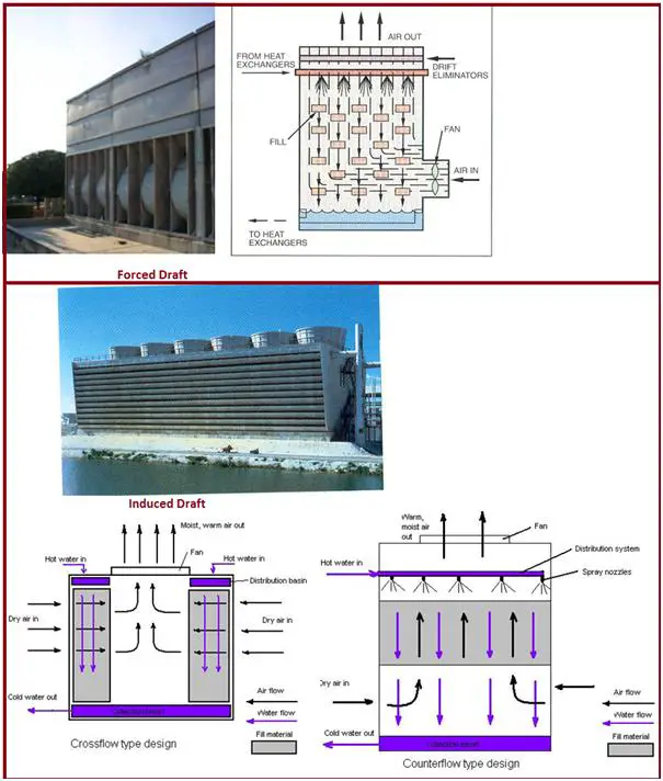
The forced draft is a mechanical draft (Fig. 1) tower
blower type fan at the intake
Fan forces air into the tower, creating high entering and low exiting air velocities.
Induced draft, a mechanical draft tower
with a fan at the discharge which pulls air through the tower
fan induces hot moist air out the discharge
low entering and high exiting air velocities, reducing the possibility of recirculation in which discharged air flows back into the air intake
Two configurations, Cross Flow and Counter Flow
Fig. 1: Mechanical Draft Towers
Cross Flow Induced Draft Cooling Towers
Airflow directed perpendicular to the water flow
Airflow enters one or more vertical faces of the cooling tower to meet the fill material
Air continues through the fill and thus past the water flow into an open plenum area
Water flows (perpendicular to the air) through the fill by gravity
Gravity distributes the water through the nozzles uniformly across the fill material
Counter Flow Induced Draft Cooling Towers
The airflow is directly opposite of the water flow
Airflow first enters an open area beneath the fill media and is then drawn up vertically
The water is sprayed through pressurized nozzles and flows downward through the fill, opposite to the airflow
Advantages of Cross Flow Towers
Low pumping head, lower first cost pumping systems
Lower energy and operating costs
Accepts larger variation in water flow without adverse effect on the water distribution system
Easy maintenance access to distribution nozzles
Low static pressure drop
Reduced drift, less make-up
More air per fan horsepower
Large diameter fans can be used so that fewer cells are required for a given capacity
Due to more fill gap choking is minimized
Cost lower than counterflow
Disadvantages of Cross Flow Towers
Larger footprint
Approach to cooling tower limited to 4 deg C
The icing of louvers during cold weather, Larger louver surface area makes icing more difficult to control
Low-pressure head on the distribution pan may encourage orifice clogging and less water breakup at the spray nozzle
Advantages of Counter Flow Towers
Increased tower height accommodates longer ranges and closer approaches (can be less than 4 deg C)
More efficient use of air due to finer droplet size from pressure sprays
Vertical air movement across the fill allows the coldest water to be in contact with the driest air maximizing tower performance
Disadvantages of Counter Flow Towers
Cost higher than Crossflow tower
Height is more
Increased system pumping head requirements
Increased energy consumption and operating costs
Difficult to inspect and clean distribution nozzles
Requires individual risers for each cell, increasing external piping costs
Fill gap is less so choking is possible
Resistance to upward air travel against the falling water results in higher static pressure loss and a greater fan horsepower than in crossflow towers
Restricted louver area at the base with the high velocity of inlet air increases the fan horsepower
The tendency for uneven distribution of air through the fill with very little movement near the walls and center of the tower
High inlet velocities are liable to suck airborne trash and dirt into the tower
When to choose – Crossflow towers?
To minimize pump head
To minimize pumping and piping first costs
To minimize operating costs
When flow variance is expected from the process
When ease of maintenance is a concern
When to choose – Counterflow towers?
When space (footprint) is a concern
When icing is of extreme concern
When pumping is designed for additional pressure drop
Material Balance of Cooling Towers
A water balance around the entire system is: M = E + B + W (where, E = Evaporation, B = Blowdown and W = Windage losses, in m3/hr)
Evaporation Losses, E = {C X (T1- T2) X Cp} / Hv (where, C = amount of circulating water in m3/hr, T1/T2 = return/supply temperature, Cp = specific heat of water and Hv = latent heat of vaporization of water)
Windage or drift losses, W from large-scale industrial cooling towers, in absence of manufacturer’s data, may be assumed to be:
W = 0.3 to 1.0 percent of C for a natural draft cooling tower without windage drift eliminators
W = 0.1 to 0.3 percent of C for an induced draft cooling tower without windage drift eliminators
W = about 0.005 percent of C (or less) if the cooling tower has windage drift eliminators
Since the evaporated water has no salts, a chloride balance around the system is: M (Xm) = B (Xc) + W (Xc) = Xc (B + W) where, M = Make-up quantity in m3/hr, Xm = concentration of chlorides in make-up water in ppmw and Xc = concentration of chlorides in circulating water in ppmw.
Xc/Xm = Cycles of concentration = ppm chloride in circulating water/ppm chloride in make-up water = M / (B+ W) = M / (M – E) = 1 + { E / (B + W) }
Lower COC means high operating cost due to higher make-up
As the cycles of concentration increase the water may not be able to hold the minerals in solution, once solubility is exceeded, they precipitate and cause fouling in exchangers
Cycles of concentration vary from 3 to 5 depending upon the make-up water quality
Components of a Cooling Tower
Cooling Tower Hot Water distribution system – The collection header and branch headers to the individual cells via flow control valves
Types of pump used – Horizontal Centrifugal, Vertical turbine
Fill, the heat transfer surface, most important component of a cooling tower
The efficiency of the tower depends upon its ability to promote both the maximum contact surface and the maximum contact time between air and water
Two basic types of fill – Splash type and Film type
In crossflow, either type can be applied but in counterflow, through either type can be used but tends toward almost exclusive use of the film fills
Material of Construction of Cooling Towers
Wood: Available, Workable, Low Cost, and Durable.
Metals: Steel, Cast Iron, copper alloys, and aluminum alloys. Special care required for corrosion control for metals other than steel. Used for fan hubs, basins, partitions, fan cylinders, bolts, nuts, washers, gear cases, anchor castings, etc.
Plastics: Capable to be molded into single parts of complex shape and dimensions. Used for fan blades, fan cylinders, fill supports, drift eliminators, louvers, etc.
Concrete: Higher initial cost but decreased fire risk and higher load-carrying capacity.
Special Types of Cooling Towers
Dry Cooling Towers
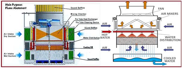
Hybrid Cooling Towers (also called plume abatement towers)
Dry Cooling Towers
Basically an air-cooled heat exchanger
Sensible cooling of water through finned coils
The low temperature of inlet air is essential
Less efficient cooling – large surface areas
Water temperatures higher than evaporative type cooling towers
Hybrid Cooling Towers
Combines both dry and wet sections
Operational flexibility in case of variation in ambient conditions
More effective cooling than dry type towers
Avoids plume formation
Hybrid Cooling Towers-Sub Types
Parallel path tower
Series path tower
Adiabatic air pre-cooler
Parallel Path Towers (Fig. 2):
Coil section located vertically on top of the fill section
Induced draft fan
Hot water flows through the coil and fills section in series
Parallel streams of airflow through the coil and fill sections
Dry and saturated air streams mix in the fan section
Fig. 2: Parallel Path Towers
The ratio of two sections depending on the inlet air characteristics
Supply of air to each section may be adjusted with louvers at the inlet
During low ambient temperatures fill section may be completely isolated
Requires more height of the tower
Series Path Tower:
Air flows through the coil and fills sections in series
Induced draft fan – cross flow
The coil may be before or after fill section
De-saturation of the air stream in the coil section
Less height of tower compared to parallel path towers
Less flexibility of operation on airside
The proximity of the dry coil to fill section leads to:
Impingement
Scaling problems
Restricted airflow.
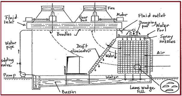
Adiabatic Air Pre-Cooler (Fig. 3):
Also known as a humidified air cooler
Effective for low RH areas
Fill section adjacent to dry section with drift eliminator in between
Finned tube bundle located on top of dry section
The induced draft fan draws air through fill and coil sections in series
Two water streams – closed loop through the coil and open loop through the fill
Fig. 3: Adiabatic Air Pre-Cooler
Water re-circulated infill section
Air, cooled in the fill section, exits in the saturated condition
Process water-cooled in the coil with outlet air from fill section
Air at the outlet of coil section exits at a higher temperature and in unsaturated condition
Water circuit in an open loop can be shut-off during winter
Less impingement
Existing evaporative towers can be retrofitted
Disadvantages:
Two water circuits mean additional accessories and chemical treatment
Overall space requirement increases
Comparison of Hybrid and Evaporative Towers
Hybrid towers have:
Fewer problems of water loss
No plume formation
More flexibility in operation
Bigger sizes
More accessories
Higher fan powers
Buried/Underground Piping Stress Analysis using START-PROF
This Tutorial Video will explain the methodology used during Buried (Underground) Piping (Pipeline) Stress Analysis with PASS/START-PROF software.
Stress Analysis of Underground piping always creates difficulty for stress engineers due to various additional considerations compared to the above-ground piping system. Various additional parameters like soil properties, piping soil interaction, etc. need to be considered in the analysis. Stress Analysis can be performed using ASME B31.3, B31.4, B31.8, ISO-14692, and all other international codes.
Online Buried Pipe Stress Analysis Course
If you wish to attend an online course on buried pipe stress analysis using Caesar II software then join the same by clicking here.
Reboilers are typical heat exchanger that produces vapor to drive fractional distillation separation. In classical fractional distillation services, all the vapor to drive the separation comes from the reboiler. (Alternatively, externally generated vapor, feed preheat, or inter-reboiler systems may be used). Proper reboiler operation is vital to effective distillation. Reboilers are specific types of heat exchangers that are used to generate a vapor flux to feed to a distillation tower. For any distribution column, reboilers are an essential part and they play an important role in the proper distillation process.
What is a Reboiler?
A reboiler is a heat exchanger used in distillation or other types of chemical processes where a liquid mixture needs to be separated into its individual components. The reboiler is a device that provides heat to the bottom of the distillation column, where the liquid mixture is boiled and the vapor rises up the column to be condensed and collected.
The reboiler is typically located at the base of the distillation column, and it is used to re-vaporize the liquid that has condensed at the bottom of the column. The heat provided by the reboiler causes the liquid to vaporize and rise up the column again, where it can be separated from the other components in the mixture.
The term “reboiler” comes from the fact that it is used to reboil the liquid that has condensed at the bottom of a distillation column. In a distillation process, the liquid mixture is heated to its boiling point, causing it to vaporize and rise up the column. As the vapor rises, it cools and condenses at the top of the column, forming a liquid that collects in a tray or basin at the bottom of the column.
The reboiler is then used to reheat this liquid, causing it to vaporize again and rise up the column for further separation. Essentially, the reboiler reboils the liquid that has already been boiled once in the distillation process, hence its name.
Types of Reboilers
Reboilers are classified depending on the orientation of the reboiler and the type of circulation used.
Depending on the reboiler orientation there are two types of reboilers:
Vertical Reboiler (Fig. 2) and
Horizontal Reboiler (Fig. 1 and 3)
Vertical vs Horizontal Reboilers
The main differences between vertical and horizontal reboiler are their orientation, size, and heat transfer characteristics.
Vertical reboilers are designed with a vertical orientation, and the heat transfer surface is typically arranged in the form of tubes or bundles that run vertically through the reboiler. The liquid to be heated is typically circulated through the tubes, while the heat source is located at the bottom of the reboiler.
Horizontal reboilers, on the other hand, are designed with a horizontal orientation, and the heat transfer surface is arranged in the form of tubes or bundles that run horizontally through the reboiler. The liquid to be heated is typically circulated through the tubes, while the heat source is located at one end of the reboiler.
The choice of which type of reboiler to use depends on several factors, including the specific application, the available space, and the desired level of heat transfer. In general, vertical reboilers are preferred when there is limited horizontal space available, as they require less floor space than horizontal reboilers. Horizontal reboilers, on the other hand, are preferred when there is limited vertical space available, as they require less headroom than vertical reboilers.
In terms of heat transfer characteristics, vertical reboilers are generally better suited for processes that require high heat transfer rates, while horizontal reboilers are better suited for processes that require more gentle heat transfer.
Ultimately, the choice of which type of reboiler to use depends on the specific process requirements, and both types have their advantages and disadvantages.
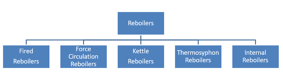
Again, depending on the types of circulation, the following five types of reboilers are widely used
Fired Reboilers
Force Circulation Reboilers
Kettle Reboilers
Thermosyphon Reboilers
Internal Reboilers
Fig. 1: Types of Reboilers
Fired Reboiler
A fired reboiler is a type of reboiler that uses a direct-fired burner to provide heat to the liquid mixture at the base of a distillation column. The burner is typically fueled by natural gas or fuel oil, and the heat generated by the burner is transferred to the liquid mixture through a heat transfer surface, such as a tube bundle or plate coil.
Fired reboilers are commonly used in distillation processes that require high heat input rates, such as those used in the petrochemical and chemical industries. They are typically more efficient than other types of reboilers, such as steam or electric reboilers, because they can provide a higher heat flux and faster heating rates.
Fired reboilers can be designed as either vertical or horizontal units, and they can be configured in various sizes and capacities to meet the specific needs of a given process. They can also be equipped with advanced controls and safety features, such as flame monitoring systems, to ensure safe and efficient operation.
One disadvantage of using a fired reboiler is that they require a continuous supply of fuel, which can be expensive and potentially hazardous. They also require periodic maintenance to ensure that the burner and heat transfer surfaces are functioning properly.
Forced Circulation Reboiler
A forced circulation reboiler is a type of reboiler that uses a pump to circulate the liquid mixture through the heat transfer surface, typically a tube bundle or plate coil. The liquid is heated by a heating medium, such as steam or hot oil, that flows over the heat transfer surface, and the heated liquid is then returned to the bottom of the distillation column.
The pump used in a forced circulation reboiler is typically a centrifugal pump, which provides the necessary pressure to overcome the pressure drop in the heat transfer surface and maintain the flow rate of the liquid.
Forced circulation reboilers are commonly used in distillation processes that require high heat transfer rates and efficient separation, particularly in processes where fouling or scaling is a concern. They are also commonly used in processes that require precise temperature control, as the flow rate of the liquid can be easily controlled using the pump.
One advantage of using a forced circulation reboiler is that it provides a high degree of heat transfer efficiency, as the liquid is continuously circulated over the heat transfer surface. This can result in a more efficient distillation process and a higher quality product.
Another advantage of using a forced circulation reboiler is that it can be easily scaled up or down to meet the needs of a specific process. The pump and heat transfer surface can be sized to match the flow rate and heat transfer requirements of the process, and multiple units can be used in parallel to increase production capacity.
However, one disadvantage of using a forced circulation reboiler is that it can be more complex and expensive to install and maintain compared to other types of reboilers. It also requires a source of heating medium, such as steam or hot oil, which can add to the overall operating cost of the distillation process.
Kettle Reboilers
A kettle reboiler is a type of shell and tube heat exchanger that is used as a reboiler in distillation processes. The kettle reboiler is a vertical cylindrical vessel that is mounted directly on top of the distillation column. The vessel contains a tube bundle that is suspended from the top of the vessel and extends down to the bottom, where it is connected to the distillation column. The tube bundle is heated by a heating medium, such as steam or hot oil, that flows through the tubes, and the liquid to be vaporized is heated by the tube bundle.
Kettle reboilers are commonly used in distillation processes that require high heat transfer rates, as they can provide a high degree of heat transfer efficiency due to their large heat transfer surface area. They are also commonly used in processes where fouling or scaling is a concern, as the tube bundle can be easily removed for cleaning or maintenance.
One advantage of using a kettle reboiler is that it can handle a wide range of liquid flow rates and compositions, making it suitable for a variety of distillation processes. It is also relatively easy to install and maintain, as it can be mounted directly on top of the distillation column.
However, one disadvantage of using a kettle reboiler is that it can be more expensive to operate compared to other types of reboilers, as it requires a large amount of heating medium to maintain the required heat transfer rate. It can also be less efficient than other types of reboilers, such as forced circulation reboilers, in terms of heat transfer per unit of the heating medium.
Thermosyphon Reboilers
A thermosyphon reboiler is a type of natural circulation reboiler that uses the natural circulation of the liquid to provide heat to the distillation process. In a thermosyphon reboiler, the liquid to be vaporized is heated by a heat transfer surface, typically a tube bundle or plate coil, that is located at the bottom of the reboiler. The heated liquid then rises up through the column due to the difference in density between the heated liquid and the cooler liquid at the top of the column, creating a natural circulation loop.
Thermosyphon reboilers are commonly used in distillation processes that require moderate to high heat transfer rates, as they can provide a high degree of heat transfer efficiency due to their large heat transfer surface area. They are also commonly used in processes that require low maintenance and are easy to operate, as they do not require any external power sources or moving parts.
One advantage of using a thermosyphon reboiler is that it is a simple and reliable means of providing heat to a distillation process. It can operate without the need for external power sources or moving parts, making it less prone to breakdowns and maintenance issues.
However, one disadvantage of using a thermosyphon reboiler is that it is less efficient than other types of reboilers, such as forced circulation reboilers, in terms of heat transfer per unit of the heating medium. It is also more sensitive to changes in the liquid flow rate and composition, which can affect the natural circulation loop and the efficiency of the reboiler.
Internal Reboilers
An internal reboiler is a type of reboiler that is installed within the distillation column itself, rather than being mounted externally. In an internal reboiler, the heating medium, typically steam or hot oil, is circulated through a coil or tube bundle that is located inside the column. The liquid to be vaporized is then heated by the coil or tube bundle, and the resulting vapor rises up through the column, where it is condensed and collected as the distillate.
Internal reboilers are commonly used in distillation processes that require a high degree of thermal efficiency and a compact design, as they can provide a large amount of heat transfer surface area within a relatively small space. They are also commonly used in processes that require a high degree of product purity, as they can minimize the number of impurities that are carried over with the vapor.
One advantage of using an internal reboiler is that it can provide a high degree of thermal efficiency, as the heat transfer surface area is located directly within the column where the vapor is being generated. This can also lead to a reduction in the size and cost of the distillation column, as the need for a separate reboiler vessel is eliminated.
However, one disadvantage of using an internal reboiler is that it can be more difficult to install and maintain compared to other types of reboilers, as it requires access to the inside of the distillation column. It can also be more prone to fouling or scaling, which can reduce its effectiveness and require more frequent cleaning or maintenance. Internal reboilers are also known as the Stab-in bundle reboiler.
Factors Influencing Reboiler Type Selection
The selection of the proper type of reboiler for any specific service is the most difficult job of reboiler design. Reboilers normally are shell-and-tube exchangers that heat up the fractionation column fluid utilizing the heat transfer from steam. Specific services may use other specialized designs including stab-ins, plate-fins, spiral-plate, and others. The purpose here is not to go into the design details of each specific type but rather to examine the selection criteria that favor one configuration over another. Since shell-and-tubes are so common, most of the discussion focuses on them but some factors favoring other designs are covered as well.
Many factors influence reboiler type selection. In the end, all these factors reduce economics. Every plant will weigh the trade-off between these factors differently. No one-size-fits-all selection exists. Major factors include:
Plot space available
Total duty required
The fraction of tower liquid traffic vaporized
Fouling tendency
Temperature approach available
Temperature approach required
Corrosion of the fluid.
Design temperature and Pressure.
Characteristics of the reboiler boiling fluid.
Heating medium requirements.
Reboiler Configurations
All of the above mentioned factors affect the desired configuration of the Reboiler. The major configuration selections include:
Forced reboiler versus natural circulation reboiler
Tube side versus shell side vaporization inside reboiler
Once-through versus process recirculation reboiler
Single-shell versus multiple-shell systems
Vertical versus horizontal reboiler
Stab-in bundles
Other types
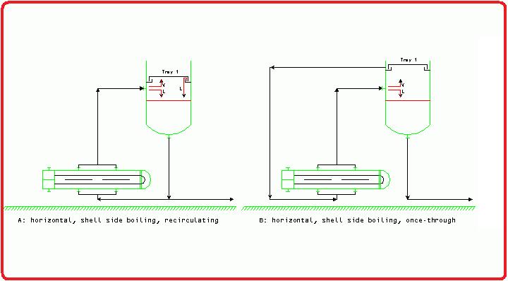
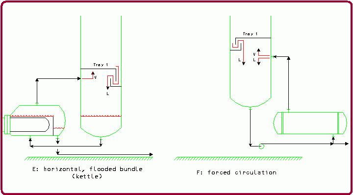
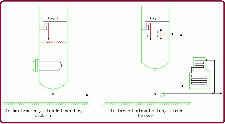
Figures 2 to 5 show common types of reboilers. Figure 2 shows two horizontal, shell-side boiling configurations. Figure 2A is a recirculating thermosyphon reboiler. Figure 2B is a once-through thermosyphon reboiler. Figure 3 shows vertical configurations. Figure 3C is a tube-side boiling configuration with the once-through flow and Figure 3D is a shell-side boiling recirculating thermosyphon. Figure 4E shows a kettle reboiler and Figure 4F shows a forced-circulation reboiler. Figure 5G illustrates a stab-in bundle and Figure 5H shows a forced-circulation, fired heater.
Fig. 2: Horizontal Shell Side Boiling Reboilers
Fig. 3: Vertical Reboilers
Fig. 4: Flooded bundle reboilers
Fig. 5: Stab-in and fired heater reboilers
Reboiler Type Selection Table
Table 1 includes the major factors in making a choice for the reboiler type selection.
Factor
Favored types
Disfavored types
Low bottoms product fraction compared to boil-up
Recirculating Kettle
Once-through
High bottoms product fraction compared to boil-up
Once-through reboiler
Recirculating
Low relative volatility systems
Recirculating
High relative volatility systems
Once-through
Recirculating
Large exchanger size or high-duty requirements
Horizontal reboiler
Vertical reboiler
Small exchangers
Vertical Stab-in
Leaks are hazardous or difficult to deal with
Stab-in
Exotic materials
Stab-in
Tight temperature approach
Spiral-plate Plate-fin
Shell-and-tube
Solids present
Kettle Spiral-plate
Plate-fin
Thermally unstable products
Recirculating (no baffle)
Kettle Once through
Tight plot plan
Vertical
Horizontal
Ample plot plan
Horizontal
High temperatures
Fired heaters
High heat fluxes
Forced circulation Flooded bundles
Natural circulation
Table. 1: Reboiler-type selection table
Other systems in addition to the ones shown here are also possible. Of course, every reboiler system’s final choice will depend upon specific design details involved. Many reboiler systems have specific characteristics that favor designs that might not be immediately apparent.
Benefits of using Reboilers
The advantages of using a reboiler in a distillation process include:
Increased separation efficiency: By providing heat to the liquid mixture at the base of the distillation column, the reboiler promotes the vaporization of the liquid, which improves the separation efficiency of the process.
Improved product quality: A reboiler can help improve the quality of the final product by separating impurities and unwanted components from the liquid mixture.
Increased production capacity: A reboiler can help increase the production capacity of a distillation process by promoting faster and more efficient separation of the liquid mixture.
Reduced energy consumption: Using a reboiler can help reduce the amount of energy needed to operate the distillation process by promoting faster and more efficient separation.
Increased process control: A reboiler can be designed with advanced control systems to regulate the heat input and optimize the distillation process, which can improve the overall process control and efficiency.
Overall, the use of a reboiler in a distillation process can provide significant advantages in terms of separation efficiency, product quality, production capacity, energy consumption, and process control.
Reboilers vs Evaporators
A reboiler and an evaporator are both types of heat exchangers used in different types of processes. While they are similar in some ways, there are some key differences between the two.
The main difference between a reboiler and an evaporator is the purpose for which they are used. A reboiler is used in distillation processes to separate a liquid mixture into its individual components, while an evaporator is used to concentrate a solution by removing its solvent through vaporization.
Another difference between the two is the location where they are used in the process. A reboiler is typically located at the bottom of a distillation column, where it provides heat for the liquid mixture to be separated, while an evaporator is typically a standalone unit used to concentrate a solution.
The design of a reboiler and an evaporator also differs. A reboiler is designed to provide heat at a controlled rate to the liquid mixture, and it may have features such as internal baffles to promote mixing and heat transfer. An evaporator is designed to promote the vaporization of the solvent and may have features such as multiple stages to increase concentration and efficiency.
In summary, while both a reboiler and an evaporator are types of heat exchangers used to transfer heat to a liquid, the main differences lie in their purposes, locations in the process, and design features.
Boiler vs Reboiler
A boiler and a reboiler are both types of heat exchangers that are used in different applications. The main differences between a boiler and a reboiler are:
Purpose: A boiler is used to generate steam or hot water for heating or power generation, while a reboiler is used to provide heat to a distillation column for the separation of liquids.
Design: A boiler is typically a large vessel that contains a heating source, such as a burner or a nuclear reactor, and a heat exchanger that transfers heat to the water or steam. A reboiler, on the other hand, is a smaller vessel or heat exchanger that is mounted directly on top of a distillation column and provides heat to the liquid inside the column.
Fluids: A boiler is designed to heat water or other fluids to a high temperature and pressure to generate steam or hot water, while a reboiler is designed to heat a liquid, such as a mixture of liquids in a distillation column, to its boiling point to generate vapor.
Operation: A boiler operates by heating the water or other fluid to a high temperature and pressure, while a reboiler operates by heating the liquid to its boiling point, allowing the vapor to rise up through the distillation column and separate into different components.
While both boilers and reboilers are heat exchangers, they are designed for different purposes and applications. A boiler is used to generate steam or hot water for heating or power generation, while a reboiler is used to provide heat to a distillation column for the separation of liquids.
Conclusion
In the complex world of industrial processes, reboilers stand as silent workhorses, diligently providing the heat needed for distillation and fractionation operations. Their versatile designs cater to various applications, ensuring the efficient separation of mixtures into valuable components. As industries continue to evolve and demand higher efficiency, reboilers will undoubtedly remain a crucial component, driving innovation and sustainable production across the board.
Flange gaskets may not be the most glamorous components in the industrial piping world, but they play a critical role in maintaining the integrity and efficiency of flanged connections. Whether you’re familiar with them or just starting to explore their importance, this comprehensive guide will take you through the ins and outs of piping flange gaskets, their types, applications, and best practices.
What is a Flange Gasket?
A flange gasket is one of the basic elements for flanged joints in the piping system of operating plants. A flange gasket is defined as a sealing material or a combination of materials clamped between two separable mechanical members of a mechanical joint (flanged joint) which produces the weakest link of the joint. The leak-proof sealing is ensured by different types of gaskets. In oil and gas, chemical, petrochemical, and other heavy industries, many different types of gaskets are widely used. Flange gaskets come in a variety of shapes, sizes, and materials to accommodate different pressures, temperatures, and media.
A flange gasket is a soft sealing material closed between two flanges in order to make a leak-free sealing application. For proper functioning and cost-effectiveness of flanged joints:-
Flanges must be enormous stiff and massive.
Flange faces should be super smooth.
Flanges should be closed without tension on the pipes
Flanges should be 100% parallel.
But the above is economically not feasible.
Functions of a Flange Gasket in a Piping Flanged Joint
Flange Gaskets in piping are used to create a static seal between two stationary members of a mechanical assembly (the flanged joint) that maintains a leak-proof sealing during operation. The gasket material flows (interpose a semi-plastic material between the flange facings) into the imperfections between the mating surfaces by an external force (bolt tightening force) and maintains a tight seal (seals the minute surface irregularities to prevent leakage of the fluid) under all operating conditions.
The amount of flow (seal) of the gasket material that is required to produce a tight seal is dependent upon the roughness of the surface. The gasket must be able to maintain this seal under all the operating conditions of the system including extreme upsets of temperature and pressure. Therefore, it is important to ensure proper design and selection of the gaskets to prevent flange-leakage problems and avoid costly shutdowns of the process plants.
So the main functions of a flange gasket are:
The gasket material has to fill the uneven surface of the flange in order to prevent leakage between the gasket and the flange surface.
The gasket material has to overcome the misalignment of the flanges in order to prevent leakage between the gasket and the flange surface.
Leakage through the gasket has to be reduced to the minimum against internal pressure-Emission
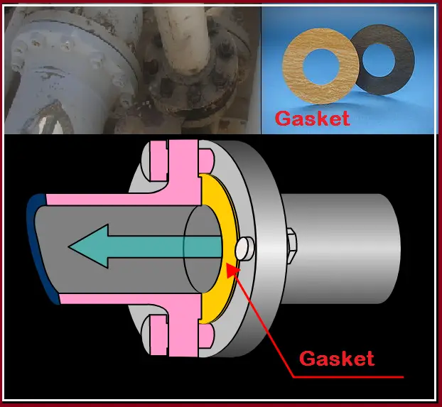
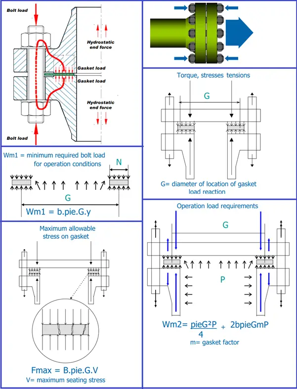
Fig. 1: Bolted Joints with Gaskets
How does a Flange Gasket Work?
Refer to the above figure (Fig. 1) which shows the three major forces acting on the gasket. Normally the gasket is seated by tightening the bolts on the flanges before the application of the internal pressure. Upon the application of the internal pressure in the joint, an end force (Hydrostatic end force) tends to separate the flanges and decrease the unit stress (Residual stress) on the gasket. Leakage will occur under pressure if the hydrostatic end force is sufficiently great and the difference between the hydrostatic end force and the bolt load reduces the gasket load below a critical value. To explain it in clear language, we can say that there are three principal forces acting on any gasket joint. They are:
Bolt Load which applies the initial compressive load that flows the gasket material into surface imperfections to form a seal.
The hydrostatic end force tends to separate flanges when the system is pressurized.
Internal pressure acting on the portion of the gasket exposed to internal pressure tends to blow the gasket out of the joint and/or bypass the gasket under operating conditions.
Even though there are other shock forces that may be created due to sudden changes in temperature and pressure. Creep relaxation is another factor that may come into the picture. The initial compression force applied to a joint must serve several purposes as listed below:
It must be sufficient to initially seat the gasket and flow the gasket into the imperfections on the gasket seating surfaces regardless of operating conditions.
The initial compression force must be great enough to compensate for the total hydrostatic end force that would be present during operating conditions.
It must be sufficient to maintain a residual load on the gasket/flange interface.
Now from a practical standpoint, residual load on the gasket must be “X” times internal pressure if a tight joint is required to be maintained. This unknown quantity “X” is what is specified as the “m” factor in the ASME Pressure Vessel Code and will vary depending upon the type of gasket being used. Actually, the “m” value is the ratio of residual unit stress (bolt load minus hydrostatic end force) on the gasket to the internal pressure of the system. The larger the value of “m”, the more assurance the designer has of obtaining a tight joint.
Types of Flange Gaskets
Depending on various parameters, gaskets for pipe flanges are classified as follows:
Gasket types based on gasket materials
Types of gaskets depending on gasket configurations
Gasket types based on the face of gaskets
Miscellaneous types of gaskets
Types of flange gaskets based on gasket materials
Based on the gasket materials used to manufacture the gasket, three types of gaskets are widely used in industrial applications. They are
Non-metallic Gaskets
Semi-metallic or Composite Gaskets, and
Metallic Gaskets
Non-metallic Gaskets
Usually, composite sheet materials are used with flat-face flanges and low-pressure class applications. Non-metallic gaskets are manufactured of non-asbestos material or Compressed Asbestos Fibre (CAF). Non-asbestos types include aramid fiber, glass fiber, elastomer, Teflon (PTFE), and flexible graphite gaskets. Full-face gasket types are suitable for use with flat-face (FF) flanges and flat-ring gasket types are suitable for use with raised-face (RF) flanges.
There are various types of rubber gaskets. Rubber gaskets are used to seal two surfaces together and prevent leakage of fluids or gases. There are several types of rubber gaskets available in the market, each with its own unique properties and characteristics. Some of the common types of rubber gaskets are:
Neoprene Gaskets: These gaskets are made from neoprene rubber, which is resistant to oil, weather, and abrasion. They are commonly used in automotive and industrial applications.
Silicone Gaskets: Silicone gaskets are made from silicone rubber, which is resistant to extreme temperatures and chemicals. They are commonly used in high-temperature applications such as oven doors and engine components.
EPDM Gaskets: These gaskets are made from ethylene propylene diene monomer rubber, which is resistant to weather, ozone, and UV radiation. They are commonly used in outdoor applications such as roofing and window seals.
Nitrile Gaskets: Nitrile gaskets are made from nitrile rubber, which is resistant to oil, fuel, and other chemicals. They are commonly used in automotive and oil industry applications.
Viton Gaskets: Viton gaskets are made from fluoroelastomer rubber, which is resistant to high temperatures, chemicals, and fuels. They are commonly used in aerospace, chemical processing, and automotive applications.
Natural Rubber Gaskets: These gaskets are made from natural rubber, which is resistant to abrasion and tear. They are commonly used in applications where flexibility and toughness are required.
The choice of rubber gasket will depend on the specific requirements of the application, such as the type of fluid or gas being sealed, the temperature and pressure of the system, and the environmental conditions.
Fig. 2: Typical PTFE Gasket
Semi-metallic or Composite Flange Gaskets
Semi-metallic gaskets are composites of metal and non-metallic materials. The metal is intended to offer strength and resiliency while the non-metallic portion of a gasket provides conformability and sealability. Commonly used semi-metallic gaskets are spiral wound, metal jacketed, Cam profile, and a variety of metal-reinforced graphite gaskets. Semi-metallic gaskets are designed for the widest range of operating conditions of temperature and pressure. Semi-metallic gaskets are used on raised faces, male and female, and tongue and groove flanges.
Fig. 3: Cam Profile Composite gasket
Metallic Gaskets
Metallic gaskets are fabricated from one or a combination of metals to the desired shape and size. Common metallic gaskets are ring-joint gaskets and lens rings. They are suitable for high-pressure and temperature applications and require a high bolt load to seal.
Flange Gasket types based on gasket configurations
Aside from the choice of gasket material, the structure or configuration of the gasket is also significant. The following paragraphs explain four major types of gaskets.
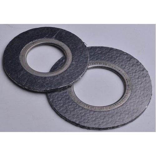
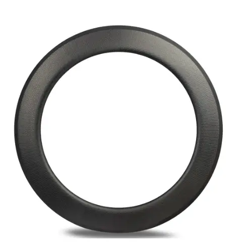
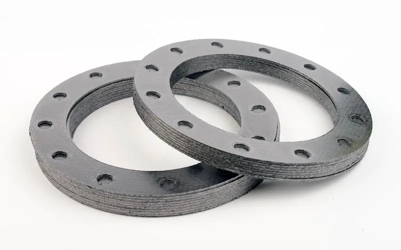
Graphite foil Gasket
The physical and chemical properties of graphite foil make it suitable as a sealing material for relatively arduous operating conditions. In an oxidizing environment, graphite foil can be used in the temperature range of –200 to +500°C, and in a reducing atmosphere, it can be used at temperatures between –200 and 2,000°C. Because graphite foil has no binder materials, it has excellent chemical resistance and is not affected by most of the commercially used common chemicals. It also has very good stress-relaxation properties.
Fig. 4: Typical Graphite Gaskets
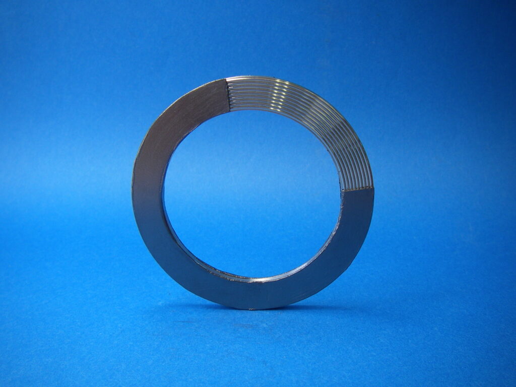
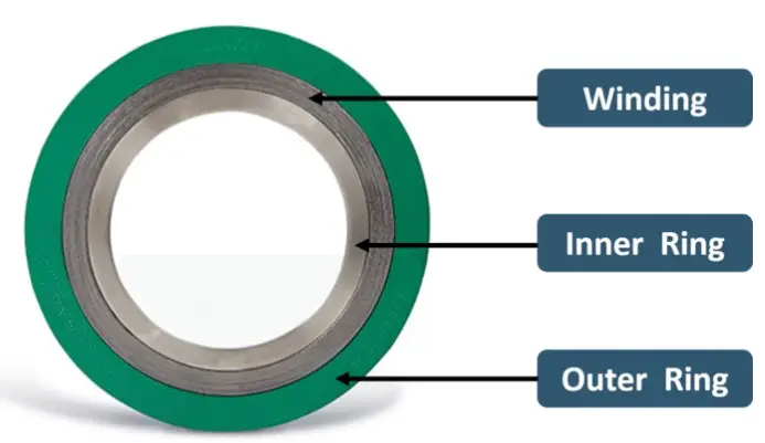
Spiral-wound Gasket
As the name implies, the spiral-wound gasket is made by winding a preformed metal strip and a filler on the periphery of a metal winding mandrel. All spiral-wound gaskets are furnished with a centering ring. In addition to controlling compression, these rings serve to locate the gasket centrally within the bolt circle. Inner rings are used where the material (such as a gasket with PTFE filler) has a tendency for inward buckling. The ring also prevents the buildup of solids between the inside diameter of the gasket and the bore of the pipe. Under vacuum conditions, the ring protects against damage that would occur if pieces of a broken component were drawn into the system. Spiral-wound gaskets can operate at temperatures from –250 to 1,000°C, and pressures from vacuum to 350 bar. Spiral-wound gaskets up to 1-in. diameter and up to class number 600 require uniform bolt stress of 25,000 psi to compress the gasket. Larger sizes and classes require 30,000 psi to compress the gasket.
Fig. 5: Typical Spiral Wound Gasket
There are several types of spiral wound gaskets available in the market, each with its own unique properties and characteristics. Some of the common types of spiral wound gaskets are:
Basic Spiral Wound Gaskets: These gaskets are the simplest type of spiral wound gaskets and are composed of a single metal strip and a soft filler material. They are commonly used in low-pressure and low-temperature applications.
Inner Ring Spiral Wound Gaskets: These gaskets have an additional metal ring on the inside of the spiral wound structure, which provides extra support and stability. They are commonly used in high-pressure and high-temperature applications.
Outer Ring Spiral Wound Gaskets: These gaskets have an additional metal ring on the outside of the spiral wound structure, which provides extra support and prevents the soft filler material from flowing out of the gasket. They are commonly used in applications where the gasket is subjected to high pressure.
Centering Ring Spiral Wound Gaskets: These gaskets have an additional metal ring in the center of the spiral wound structure, which helps to center the gasket in the flange and prevents it from slipping out of position. They are commonly used in applications where alignment is critical.
Jacketed Spiral Wound Gaskets: These gaskets have an outer metal jacket that provides additional protection against corrosive or abrasive media. They are commonly used in chemical processing and petrochemical applications.
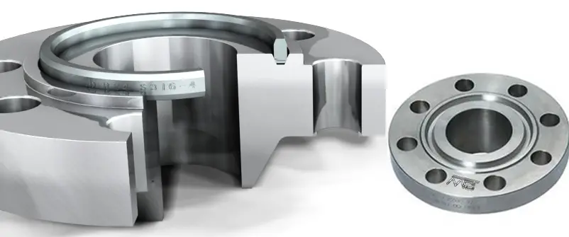
Ring-Joint Gasket
Ring-joint gaskets are commonly used in grooved flanges for high-pressure-piping systems and vessels. Their applicable pressure range is from 1,000 to 15,000 psi. These gaskets are designed to give very high gasket pressure with a moderate bolt load. These joints are not generally pressure-actuated. The hardness must be less than that of the flange material so that the proper flow of material occurs without damaging flange surfaces. The most widely used ring-joint gaskets are of the oval and octagonal types. Oval types of gaskets contact the flange face at the curved surface and provide a highly reliable seal. However, the curved shape makes it more difficult to achieve accurate dimensioning and surface finishing. Oval gaskets also have the disadvantage that they can only be used once, so they may not be the best choice for sealing flanges that have to be opened routinely. On the other hand, because they are constructed of only straight faces, octagonal-type gaskets are usually less expensive, can be dimensioned more accurately, and are easier to surface finish than oval-type flange gaskets. However, a greater torque load is required to flow the gasket material into imperfections that may reside on the flange faces. Octagonal gaskets can be used more than once.
Fig. 6: Typical Ring Joint Gasket
There are several types of ring joint gaskets available in the market, each with its own unique properties and characteristics. Some of the common types of ring joint gaskets are:
R Style Ring Joint Gaskets: These gaskets are oval or octagonal in shape and are designed to be used with R-style flanges. They are commonly used in high-pressure applications in the oil and gas industry.
BX Style Ring Joint Gaskets: These gaskets are trapezoidal in shape and are designed to be used with BX style flanges. They are commonly used in high-pressure applications in the oil and gas industry.
RX Style Ring Joint Gaskets: These gaskets are similar to R style gaskets but have a modified design that allows them to be used with RX style flanges. They are commonly used in high-pressure applications in the oil and gas industry.
IX Style Ring Joint Gaskets: These gaskets are designed to be used with IX style flanges, which are used in subsea and offshore applications. They have a unique design that allows them to seal effectively in high-pressure and high-temperature environments.
SRX Style Ring Joint Gaskets: These gaskets are similar to RX style gaskets but have a modified design that provides a tighter seal. They are commonly used in critical applications where leakage cannot be tolerated.
Corrugated-metal Gaskets
This type of flange gasket is available in a wide range of metals, including brass, copper, copper-nickel alloys, steel, Monel, and aluminum. Corrugated metal gaskets can be manufactured to just about any shape and size required. The thickness of the metal is normally 0.25 or 0.3 mm, with corrugations having a pitch of 1.6, 3.2, and 6.4 mm. The sealing mechanism is based on point contact between the peaks of the corrugations and the mating flanges
Fig. 7: Corrugated Metal Gaskets
Gasket types based on the Face of gaskets
Depending on the face of the gaskets, two types of gaskets are found. These two types of gaskets most commonly known are ring gaskets and full-face gaskets. The latter as the name implies covers the entire flange face and is pierced by the bolt holes. They are intended for use with flat-face flanges. Ring gaskets extend to the inside of the flange bolt holes and consequently are self-centering. They are usually used with raised face or lap joint flanges but may also be used with flat-faced flanges.
Miscellaneous Gasket Types
Flat Ring Gaskets
Flat-ring types of gaskets are widely used wherever service condition permits because of the ease with which they may be cut from a flat sheet and installed. They are commonly fabricated from such materials as rubber, paper, cloth, asbestos, plastics, copper, lead, aluminum, nickel, Monel, and soft iron. These gasket types are usually made in thickness from 1/64 to 1/8 in. Paper, cloth, and rubber gaskets are not recommended for use above 120° C. Asbestos-composition gaskets may be used up to 350° C or slightly higher, ferrous, and nickel-alloy metal gaskets may be used up to the maximum temperature rating of the flanges.
Fig. 8: Flat Ring Gaskets
Axial and Radial Gasket Flow under Compression
Upon initial compression, a gasket will flow both axially and radially. The axial flow is required to fill depressions in the flange facing and prevent leakage. Radial flow serves no useful purpose unless the gasket is confined. Where a flange joint is heated, a greater gasket pressure is produced due to the difference between the flange body and the bolts. This greater pressure coupled with the usual softening of the gasket material at elevated temperatures causes additional axial and radial gasket flow. To compensate for this, the flange bolts are usually re-tightened a second or third time after the joint is heated to the normal operating temperature.
Thin Gasket vs. Thick Gasket
A thick gasket will flow radially to a far greater extent than a thin gasket. Some thin gaskets show practically no radial flow at extremely high unit pressures. Consequently, for high temperatures, a thin gasket has the advantage of maintaining a permanent thickness while a thick gasket will continue to flow radially and may leak, in time, due to the resulting reduced gasket pressure. However in attempting the utmost utilization of the thin gasket advantage, one may find that the gasket selected has an insufficient thickness to seal the irregularities, in the commercial flange faces.
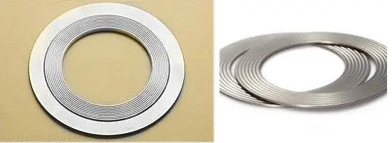
Spiral-Wound Asbestos-Metallic Gasket
The spiral wound asbestos-metallic gasket combines the advantages of both the thick and thin gasket. Although a relatively thick gasket (most common types are 0.175” thick) its spirally laminated construction confines the asbestos filler between axially flexible metal layers. This eliminates the radial flow characteristics of a thick gasket and provides the resiliency to adjust to varying service conditions. Spiral wound gaskets are available with different filler materials such as Teflon, Grafoil, etc. to suit fluid compatibility. Spiral wound gaskets used with raised face flanges usually have an inner metal ring and an outer centering ring.
Laminated gaskets
Laminated gaskets are fabricated with a metal jacket and a soft filler, usually asbestos. Such gasket types can be used up to temperatures of about 400° C to 450° C and require less bolt load to seat and keep tight than solid metal flat ring gaskets.
Fig. 9: Typical Graphite Laminated Gaskets
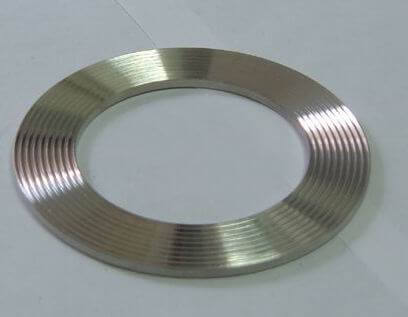
Serrated Metal gaskets
Serrated metal gaskets are fabricated of solid metal and have concentric grooves machined into the faces. This greatly reduces the contact area on initial tightening thereby reducing the bolt load. As the gasket is deformed, the contact surface area increases. Serrated types of gaskets are useful where soft gaskets or laminated gaskets are unsatisfactory and the bolt load is excessive with a flat-ring metal gasket. Smooth-finished flange faces should be used with serrated gaskets.
Fig. 9: Serrated Metal gasket
Corrugated Gaskets with Asbestos filling
Corrugated gaskets with asbestos filling are similar to laminated gaskets except that the surface is rigid with concentric rings as in the case of serrated gaskets. Corrugated gaskets require less seating force than laminated or serrated gaskets and are extensively used in low-pressure liquid and gas services. Corrugated metal gaskets without asbestos may be used to a higher temperature than those with asbestos filling.
Ring-Joint Gaskets
Two standard types of ring-joint gaskets are available for high-pressure service. One type has an oval cross-section, and the other has an octagonal cross-section. These rings are fabricated of solid metal, usually soft iron, soft steel, Monel, 4-6% chrome, and stainless steel. The alloy-steel rings should be heat treated to soften them.
It is recommended that the ring joint gasket be used for class 150 flanged joints. When the ring joint or spiral wound gasket is selected, it is recommended that line flanges be of the welding neck type.
Fig. 10: Typical Gasket in piping flanged Joint
Parameters Affecting Flange Gasket Performance
The performance of the gasket in a flanged joint is affected by a number of factors. All of these factors must be taken into consideration when selecting a gasket:
Effect of Flange Load
All gasket materials must have sufficient flange pressure to compress the gasket enough to ensure that a tight, unbroken seal occurs. The flange pressure or minimum seating stress, necessary to accomplish this is known as the “y” factor. This flange pressure must be applied uniformly across the entire seating area to achieve perfect sealing. However, in actual service, the distribution around the gasket is not uniform. The greatest force is exerted on the area directly surrounding the bolts. The lowest force occurs mid-way between two bolts. This factor must be taken into account by the flange designer.
Effect of Internal Pressure
While in service, as soon as pressure is applied to the vessel, the initial gasket compression is reduced by the internal pressure acting against the gasket (blowout pressure) and the flanges (hydrostatic end force). To account for this, an additional preload must be placed on the gasket material. An “m” or maintenance factor has been established by ASME to account for this preload. The “m” factor defines how many times the residual load (original load minus the internal pressure) must exceed the internal pressure. In this calculation, the normal pressure and the test pressure should be taken into account.
Effect of Temperature
The effects of both ambient and process temperature on the gasket material, the flanges, and the bolts must be taken into account. These effects include bolt elongation, creep relaxation of the gasket material, or thermal degradation. This can result in a reduction of the flange load. The higher the operating temperature, the more care needs to be taken with the gasket material selection. As the system is pressurized and heated, the joint deforms. Different coefficients of expansion between the bolts, the flanges, and the pipe can result in forces that can affect the gasket. The relative stiffness of the bolted joint determines whether there is a net gain or loss in the bolt load. Generally, flexible joints lose bolt load.
Effect of Fluid
The media being sealed is usually a liquid or a gas with gas being harder to seal than a liquid. The effect of temperature on many fluids causes them to become more aggressive. Therefore, a fluid that can be sealed at ambient temperature, may adversely affect the gasket at a higher temperature. The gasket material must be resistant to corrosive attack from the fluid. It should chemically resist the system fluid to prevent serious impairment of its physical properties.
Surface Finish of the Gasket
The surface finish of a gasket — which consists of grooves or channels pressed or machined onto the outer surface — governs the thickness and compressibility required by the gasket material to form a physical barrier in the clearance gap between the flanges. A finish that is too fine or shallow is undesirable, especially on hard gasket materials, because the smooth surface may lack the required grip, which will allow extrusion to occur. On the other hand, a finish that is too deep will yield a gasket that requires a higher bolt load, which may make it difficult to form a tight seal, especially when large flange surfaces are involved. Fine machining marks applied to the flange face, tangent to the direction of applied fluid pressure can also be helpful. Flange faces with non-slip grooves that are approximately 0.125 mm deep are recommended for gaskets more than 0.5 mm thick; and for thinner gaskets, grooves 0.065 mm deep is recommended. Under no circumstances should the flange-sealing surface be machined with tool marks extending radially across the gasket-sealing surface; such marks could allow leakage.
Effect of Flange Gasket Thickness
For a given material, it is a general rule that a thinner gasket is able to handle higher compressive stress than a thicker one. However, thinner materials require a higher surface finish quality. As a rule of thumb, the gasket should be at least four times thicker than the maximum surface roughness of the flange faces. The gasket must be thick enough to occupy the shape of the flange faces and still compress under the bolt load. In situations where vibration is unavoidable, a thicker gasket than the minimum required should be employed.
Gasket Width
In order to reduce the bolt load required to produce a particular gasket pressure, it is advisable not to have the gasket wider than is necessary. For the given gasket stress, a raised face flange with a narrow gasket will require less preload and thus less flange strength than a full-face gasket. In general, high-pressure gaskets tend to be narrow.
Stress Relaxation
This factor is a measure of the material’s resiliency over a period of time and is normally expressed as a percentage loss per unit of time. All gasket material will lose some resiliency over time, due to the flow or thinning of the material caused by the applied pressure. After some initial relaxation, the residual stress should remain constant for the gasket.
Effect of Gasket Outer Diameter
For two gaskets made of the same material and having the same width, the one with a larger outer diameter will withstand higher pressure. Therefore, it is advisable to use a gasket with an external diameter that is as large as possible.
Codes & Standards for Gasket Design
The following standards are normally adopted for specifying gaskets.
ASME B16.21 Non-metallic flat gaskets for pipe flanges.
ASME B16.20 Metallic Gaskets for steel pipe flanges, Ring Joints, Spiral Wounds, and Jacketed
IS2712 Specification for compressed Asbestos fiber jointing.
BS 3381 Spiral Wound Gaskets to suit BS 1560 Flanges
How to Select a Gasket? Flange Gasket Selection
The gasket material selected should be one that is not adversely affected physically or chemically by the service conditions.
The following factors dictate the proper selection of gaskets.
The gasket material should be compatible with the fluid service.
Ability to withstand the pressure-temperature of the system.
The service life of the gasket
Gasket material must be corrosion-resistant against the service fluid.
The gasket shall be readily available.
Economy- Clients always prefer cheap and reliable gaskets.
Flange Construction- The thickness of the flange has an effect on the bolt load and therefore seating stress. Thin and deformed flanges need softer gaskets.
Standardization
Quality Stud bolts
Emission Parameters- Each selected gasket has different emission parameters.
Flange Misalignment- Maximum misalignment of flanges will be 0.4 mm.
Gasket Materials
Depending on service, temperature, and pressure gaskets can be of various materials as listed in the table below:
Metallic
Non-Metallic
Winding Strips of Spiral Wound Gaskets
Filler Material for Winding
Low Carbon Steel
PTFE
Stainless Steel
PTFE
Stainless Steel
Compressed Asbestos
Duplex Steel
Graphite
Soft Iron
Rubber
Monel
Chrome-Moly
Ceramic Fiber
Titanium
Table: Gasket Materials
Color-coded chart for the type of flange gasket identification
Spiral wound gaskets with stainless steel core and PTFE or graphite as the filler material is the most widely used gasket for process industries. For inspection and identification purposes, ASME B16.20 provides a Color Coding Chart as shown in Fig. 11 below:
Fig. 11: Color Coded Chart for Gaskets
The color coating is painted on the ring’s outside surface allowing the inspector to identify the windings material.
Characteristics of a Gasket
The gasket material has to be soft in order to compress this in the irregularities of flanges.
The gasket should be Gas-Liquid tight so that it does not leak or cause emissions.
The gaskets should not creep under the influence of stress and temperature. This could result in lower bolt stresses and possible leakage.
The resilience of the gasket should take static and dynamic effects due to stress, temperature, and pressure.
The gasket has to withstand internal pressure without being blown out.
The gasket should be capable of achieving sealing at elevated temperatures.
It has to be resistant to the chemical attack of the medium without polluting the media.
It should possess anti-stick properties such that when opening the flange, the gasket has to lose easily from the flange.
It has to be stiff enough to make installation as easy as possible.
Why do Gaskets Leak?
Gaskets may leak due to any one or more of the following reasons:
Damage during assembly
Poor Gasket selection
Excessive flange rotation
Gasket damage or relaxation due to flange rotation
Gasket damage due to differential thermal expansion
Incorrect assembly bolt load
Load loss due to thermal fluctuation
Gasket load loss due to pressure and or piping loads
excessive gasket relaxation
Excessive gasket load
What costs are involved with a flange gasket failure?
Low profit due to leakage
Cost of online sealing with clamps
Cost of re-matching
Cost of replacement equipment
Cost of Engineering and maintenance hours spent addressing leakage
Report of incidents and additional paperwork
Pollution of environment
Cleaning costs
Possible personal injuries
Cost of disassembly, repair, and machining
What could engineering do to prevent leakage through Gaskets?
Proper selection of the correct assembly bolt stress
Correct location, constraint, and width of the sealing
Consideration of bending loads, and misalignment.
Quantify effects of gasket creep/relaxation
Quantify the effects of temperature and pressure
Maximum permissible assembly load
Correct gasket selection
Root cause analysis
Basic Calculations for Gasket Selection for a Flanged Joint
Basic calculations required during gasket selection are provided in the following image (Fig. 12)
Fig. 12: Basic gasket calculations
Advantages and Disadvantages of Flange Gaskets
Advantages of gaskets:
Sealing Performance: Gaskets are designed to provide a reliable and leak-free seal between two mating surfaces. They are capable of sealing under high pressures and temperatures, as well as in corrosive and abrasive environments.
Flexibility: Gaskets are available in a wide range of materials, sizes, and shapes, making them suitable for a variety of applications. They can be easily customized to meet the specific requirements of the application.
Cost-effective: Gaskets are generally less expensive than other sealing methods, such as welding or brazing. They can also be easily replaced if they become damaged or worn out.
Easy to Install: Gaskets are easy to install and require minimal equipment or tools. This makes them ideal for applications where downtime needs to be minimized.
Disadvantages of gaskets:
Compatibility Issues: Gaskets are made from a variety of materials, and not all materials are compatible with all fluids or gases. It is important to select the correct gasket material for the specific application to ensure compatibility and prevent leakage.
Maintenance: Gaskets require regular maintenance to ensure they remain in good condition and provide a reliable seal. This can include inspecting, cleaning, and replacing gaskets as needed.
Compression Set: Over time, gaskets can lose their ability to seal due to compression set. This occurs when the gasket is compressed for an extended period and does not return to its original shape when the pressure is released. This can result in leakage and reduced sealing performance.
Flange Condition: Gaskets rely on a flat and smooth flange surface to provide an effective seal. If the flange is damaged or corroded, the gasket may not be able to seal properly, resulting in leakage.
Difference between Seals and Gaskets
Both gaskets and seals are used to prevent fluid or gas leakage between two mating surfaces, but there are some key differences between them:
Design: Gaskets are typically flat, static components that are placed between two mating surfaces and compressed to form a seal. Seals, on the other hand, are dynamic components that move relative to each other and may require a more complex design, such as lip seals or O-rings.
Material: Gaskets are usually made from compressible materials, such as rubber, cork, or paper, that can conform to irregularities in the mating surfaces. Seals are typically made from materials that can resist wear, abrasion, and chemicals, such as polyurethane, Viton, or Teflon.
Function: Gaskets are primarily used to seal static applications, such as pipe flanges or valve covers, while seals are used to seal dynamic applications, such as rotating shafts or hydraulic cylinders.
Pressure: Gaskets are generally designed to withstand lower pressures, while seals are designed to withstand higher pressures and provide a more secure seal.
Placement: Gaskets are usually placed between two flat surfaces, while seals are typically placed around a rotating or moving component.
Applications of Flange Gaskets
Flange gaskets find applications across a plethora of industries and scenarios:
Oil and Gas Industry: In pipelines, refineries, and petrochemical plants, flange gaskets prevent the leakage of hazardous fluids, ensuring safety and operational efficiency.
Food and Beverage Industry: Flange gaskets are essential in maintaining hygienic conditions by preventing contamination and leakage in food processing and beverage production.
Chemical Industry: Chemical processes often involve aggressive substances. Flange gaskets prevent leaks that could lead to dangerous chemical reactions and environmental contamination.
Water Treatment Plants: Gaskets ensure leak-free connections in water treatment facilities, preventing water loss and ensuring the quality of treated water.
Power Generation: In power plants, flange gaskets play a crucial role in maintaining steam and fluid integrity, contributing to the overall efficiency of the power generation process.
Best Practices for Using Flange Gaskets
Material Selection: Choose the right gasket material based on the application’s temperature, pressure, and the nature of the fluid being conveyed.
Surface Preparation: Properly clean and prepare flange surfaces to ensure optimal gasket performance. Any irregularities on the flange surfaces can lead to leaks.
Correct Installation: Follow manufacturer guidelines for proper gasket installation, including torque specifications and tightening sequences.
Regular Inspection: Periodically inspect gaskets for signs of wear, damage, or degradation. Replace gaskets if necessary to prevent potential leaks.
Environmental Considerations: Factors in the surrounding environment, such as temperature fluctuations and exposure to chemicals, when selecting gasket materials.
Storage: Store spare gaskets in a cool, dry place away from direct sunlight and extreme temperatures to prevent premature degradation.
In summary, piping flange gaskets are generally static components that provide a seal between two flat surfaces, while seals are dynamic components that provide a seal around moving or rotating components. Piping Gaskets are usually made from compressible materials, while seals are made from materials that can withstand wear, abrasion, and chemicals. Flange gaskets might seem like small components, but their impact on industrial operations cannot be overstated. By choosing the right type of gasket, installing it correctly, and ensuring regular maintenance, industries can prevent costly leaks, ensure safety, and maintain operational efficiency.
Frequently Asked Questions (FAQs)
1. What is a gasket?
A gasket is a mechanical seal that fills the space between two mating surfaces to prevent the leakage of fluids or gases under compression. They are commonly used in industrial applications to ensure a tight and reliable seal.
2. Why are gaskets important in piping systems?
Gaskets play a crucial role in piping systems to prevent leaks and ensure the integrity of the system. They help maintain the pressure, temperature, and fluid containment within the pipes.
3. How do I choose the right type of gasket for my application?
The choice of gasket depends on several factors, including the type of fluid or gas being transported, temperature, pressure, and the materials of the mating flanges. Our article provides detailed information on various types of gaskets and their suitable applications.
4. What are the common materials used for gaskets?
Gaskets can be made from various materials, such as rubber, metal, graphite, and PTFE (Teflon). The choice of material depends on the specific requirements of the application.
5. Are piping flange gaskets reusable?
The reusability of a gasket depends on the material and condition. Some gaskets can be reused if they are in good condition after disassembly, while others may need replacement.
6. What are the different types of gaskets mentioned in the article?
Our article covers various types of gaskets, including spiral wound gaskets, ring-type joint (RTJ) gaskets, soft-cut gaskets (non-metallic gaskets), and metal gaskets. Each type has its unique characteristics and applications.
7. Can I use any piping flange gasket for high-temperature or high-pressure applications?
Not all gaskets are suitable for high-temperature or high-pressure environments. It’s essential to choose a gasket that is specifically designed to withstand the conditions of your application. The article provides guidance on gasket selection based on these factors.
8. How do I install a gasket correctly?
Proper installation of gaskets is crucial for their effectiveness. Our article offers guidance on the correct installation procedures, including torque values and alignment tips.
9. Are there any alternatives to traditional flange gaskets?
In some cases, alternatives like gasketless flange connections or sealants may be used instead of traditional gaskets. The choice depends on the application and specific requirements.
10. Where can I purchase gaskets for my piping system?
Gaskets can be sourced from various suppliers, including local hardware stores, specialized gasket manufacturers, and online retailers. It’s important to ensure that the gaskets you purchase meet the specifications required for your application.
11. How do I determine if a flange gasket needs replacement?
Flange Gaskets may need replacement if they show signs of wear, damage, or leakage. Regular inspection and maintenance are essential to identify when a gasket requires replacement.
As per Code ASME Section III, the Stress Intensification Factor or SIF is defined as the Fatigue Correlation Factors that compare the fatigue life of Piping Components (Tees, branch connections) to that of girth butt welds in straight pipe subjected to bending moments.
Note that, Stress Intensification factors are often confused with stress concentration factors, stress coefficients, or other stress indices used in various mechanical design and fracture mechanics problems. The stress intensification factor in piping stress analysis provides the fatigue correlation of piping elbow and branch connections for evaluating moment loading.
History of Stress Intensification Factor
Markl Fatigue Curve for Straight Pipe (Fig. 1):
Fig. 1: Markl Fatigue Curve for Butt Welded Steel pipe
Markl stress intensity factor: iS = 245,000N-0.2
i =( CN-0.2)/S
Where
i=Stress intensification factor
C=245,000 for carbon steel materials
N=Cycles to failure
S=Nominal stress amplitude
Markl Stress Intensity Factor is based on deflection control, fully reversed, cyclic bending fatigue tests.
Stress Intensification Factor Equation
As per Section III, for class 2 & 3 piping and B31.1
Effect of Pressure on Stress Intensification Factor:
Fig. 4: Calculation showing the effect of pressure on SIF
Finite Element Methods for Stress Intensification Factor Calculation
The various methods for calculating Stress Intensity Factor are
Analytical Methods defined by Piping Codes
FEM techniques
The user can see that the basic SIF procedure is:
Build the model.
Apply a moment through the nominal attached pipe.
Read the highest stress from the resulting plot.
Divide by M/Z to get the SIF.
The Fem Software widely used for calculating Sif are
FE-pipe
Ansys
Stress Intensification Factor Calculations
The basic definition of stress intensification factor (SIF) is:
SIF = (Actual Peak Stress in Part)/( Nominal Stress in Part)
The nominal stress in the part for a piping component subject to bending loads is M/Z where “M” is the moment that the pipe exerts on the component, and Z is the section modulus of the matching pipe welded to the part being analyzed.
Example Case:
For example, when Stress Intensity Factors are needed for a large D/T “Wye” Fitting, there are usually four SIFs involved.
one for the in-plane moment about the wye,
one for the out-plane moment
For both the main header and branch sections.
An example, demonstrating this calculation for a 32×0.375 wye fitting is shown in the example.
Markl’s definition of the SIF is the ratio of the actual stress in the part due to a moment “M”, divided by the nominal stress in a girth (circumferential) butt weld due to a similar moment “M”.
B31 Stress Intensity Factor (SIF) = Actual Stress in Part (due to M)/ Stress in Girth Butt Weld (due to M)
Fig. 5: FEM model for Y-type fitting.
Two load cases for the model are set up automatically by FE/Pipe.
They are
Operating, and
Occasional
Various displacements and stresses from each load case are shown in Fig 6 and Fig 7.