Winterization Systems are required in refineries, petrochemical plants, and similar plants to protect equipment and piping against solidifying or coagulation of contents. Winterization in processing plants is normally achieved by using Steam Tracing, Steam Jacketing, Electrical Tracing, or Process Heating. This article will highlight the requirements for the basic design of the Winterization System.
Data Required for Winterization System Design
The data to be used for the design of winterization should be obtained from, but not limited to, the following documents ;
- Process Flow Diagram (PFD)
- Basic Engineering Design Data (BEDD)
- Piping & Instrument Diagram (P&ID)
- Plot plan
- Equipment datasheet
- Piping material specification
Plants Requiring Winterization
- Winterization for process fluids shall be considered in all circumstances, appropriately for the fluids and local ambient conditions.
- Winterization of water and steam condensate piping
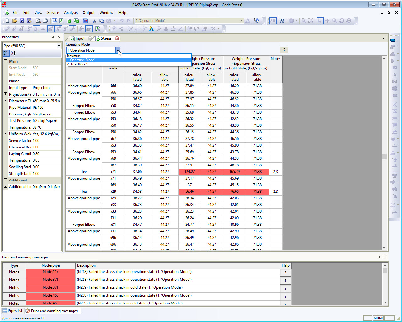
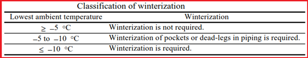
The following table gives criteria for the requirement of winterization
Winterization of Process Piping
Basic Principle:
Process piping where the pour point or solidifying point of the internal fluid is higher than the lowest ambient temperature shall be winterized. Unless otherwise specified, the fluid temperature shall be maintained above the solidifying point or at least 10°C above the pour point.
For liquid sulfur lines, steam jacket piping or electric heat tracing shall be applied to maintain the fluid temperature between 118 °C and 158°C.
For highly viscous fluids such as asphalt and bitumen, the fluid temperature shall be maintained, applying steam tracer piping or steam jacket piping, at temperatures exceeding the pour point +10°C or temperatures giving a kinetic viscosity of 300 CST (Allowable maximum viscosity during the use of centrifugal pumps) or lower, whichever is higher.
Appropriate measures to prevent fluids from temperature drop are taken for piping in which fluids are always flowing (on-stream) while the plant is being operated. The necessity of winterization, therefore, should be studied for the case where the plant stops operating.
Tank yards have many items of piping, in which fluids are not always flowing (not on-stream). Care should be taken on this point.
Winterization Requirements for Liquid Lines
The following winterization requirements should be applied to the liquid lines containing a fluid that has a higher pour point or solidifying point than the lowest ambient temperature.
(1) Winterization Philosophy for Lines always on-stream:
- (a) Bare pipelines, in which the liquid is likely to coagulate within about 12 hours after the liquid stops flowing, should be hot insulated.
- (b) Hot-insulated lines, in which the liquid is likely to coagulate within about 12 hours after the liquid stops flowing, should be steam traced, even though the liquid operating temperature is high.
(2) Winterization Philosophy for Lines not always on-stream (liquid-filled lines):
Every size of piping should be steam traced and hot insulated regardless of liquid temperatures.
The same criteria should also be applied to the following lines.
- Bypass lines for startup and shutdown
- Liquid blowdown lines
- Slop oil lines
- Standby lines in the area around the pump
- Lines to remove a small amount of water
- Instruments (LG, PG, and lead piping of PT, etc.)
- Liquid relief valves and their inlet/outlet lines
- Control valve bypass lines
- Chemical injection lines
- Makeup water lines
- Sampling lines
Vents and drains provided for the line should, in principle, be hot insulated; the requirement of steam tracing should be according to the line conditions.
(3) Winterization requirements for Lines not always on-stream (usually empty)
Such lines should be sloped so as not to form pockets and should also be provided with steam purge connections to completely empty the inside; otherwise, they should be only hot insulated.
(4) Other requirements for Winterization
- Lines, in which highly viscous fluids such as heavy fuel oil flow, should be steam traced.
- Caustic solution and amine solution lines should be steam traced when the freezing point of the solution is higher than the lowest ambient temperature.
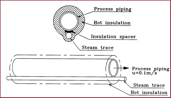
- Steam tracing of caustic and amine solution lines should be provided with insulating spacers to prevent alkali embrittlement.
Winterization Requirements for Vapor Lines Saturated with Steam
(1) Winterization for Lines always on-stream
- (a) The upstream side of the lines of orifice plates or control valves, in which steam could possibly condense, should be hot insulated. The amount of condensate generated from the gas line has to be calculated by estimating the temperature drop and consequent partial pressure decrease of steam.
- (b) Lines, in which freezing of condensed water is likely to cause trouble with continuous operation, should be steam traced.
- (c) Lines are properly sloped so as not to accumulate condensate.
- (d) Lines in which ice or hydrate can be possibly formed on depressuring should be steam traced.
(2) Winterization for Lines not always on-stream
Piping should preferably be free draining. The following items should be steam traced.
- – Instruments (such as LG, LT, PG, and lead pipes of PT)
- – Bypass lines for control valves
- – Inlet line of a relief valve. In some cases, lines should only be hot insulated depending on pipe size and length, considering heat loss.
Winterization Requirements for Vapor Lines with Higher Dew Point Fluid
The following requirements should be applied to the vapor lines containing fluid that has a dew point higher than the lowest ambient temperature.
(1) Lines always on-stream
- (a) The upstream side of the lines of orifice plates or control valves, in which vapor could possibly condense, should be hot insulated.
- (b) Lines, in which condensate is likely to solidify or is corrosive, should be steam traced.
- (c) Lines, in which condensate is likely to freeze or coagulate due to depressurization during shutdown operation, should be steam traced.
- (d) Piping should preferably be free draining.
- (e) Pockets where condensate accumulates, which may have adverse effects on the indications of instruments (such as PG, and lead pipes of PT), should be steam traced.
- (f) Lines, which are likely to have adverse effects on continuous operation due to the condensing of the fluid, should be hot insulated.
(2) Lines not always on-stream
Winterization of Utility Piping
Water Piping-Main pipes should, in principle, be buried below the freezing depth. Aboveground piping or underground piping buried above the freezing depth should comply with the requirements of “Winterization of Process Piping”.
Described below are precautions, in particular, for water piping.
- Piping of 2″ or less should be heat traced and hot insulated.
- For piping of 3″ or larger, which is always on-stream, measures should be established to ensure that water flow is not interrupted, as far as possible. Along with this, temperature drops in winter have to be calculated, and the piping should be hot-insulated for freeze-proofing as necessary.
- Piping, which is not always on stream, should be heat traced and hot insulated.
- A circulation line should be provided at the terminal of each header so as not to stop flowing.
- For pump coolers, water should also be circulated into spare stand-by pumps in order to minimize freezing trouble.
Winterization for Air and Nitrogen Piping
Special attention should be paid to the following.
- Instrument air and nitrogen contain little moisture. Instrument air and nitrogen piping, therefore, are not required to be hot insulated; such piping should be constructed of materials for low-temperature services considering the lowest ambient temperature.
- When plant air is dry, plant air piping may be bare. When it is not dry, it should be steam traced and insulated.
Winterization for Steam Piping
Attention should be paid, in particular, to the following items.
- Steam traps should be installed in lines where condensate is likely to accumulate such as pockets or control valve bypass lines.
- Even for the lines not frequently used, a steam trap should be installed at the inlet of each block valve to prevent freezing
Winterization for Steam Condensate Piping
- 1½” or smaller steam condensate piping should be heat traced and hot insulated.
- 2″ or larger steam condensate piping, which is always on-stream during plant operation, should be hot insulated.
- 2″ or larger steam condensate piping, which suffers from the intermittent flow of condensate accumulation for long periods of time, should be heat traced and hot insulated.
Winterization of Equipment
(1) Equipment requiring winterization:
- (a) Equipment containing water and where water accumulates for a long period of time, such as separators, flash drums, and receiver boots, from which water has to be removed.
- (b) Equipment containing fluids with a high pour point, high solidifying point, or high viscosity, will cause coagulation or hard-to-flow conditions.
- (c) Equipment that is likely to have adverse effects on the entire unit, due to the partial condensation of hydrocarbons in gas, such as fuel gas drums.
- (d) Equipment handling chemicals, such as caustic soda solution drums and inhibitor drums.
(2) Winterization of static equipment:
- (a) Of towers, vessels, and heat exchangers, those handling fluids that may freeze should be provided with a drain valve at a position allowing the fluids to be drained completely during the suspension of plant operation.
- (b) Parts of vessels (boots, etc.) that come into contact with water, nozzles, valves, and piping should be heat traced and hot insulated.
- (c) No winterization is required for the equipment which can be heated by internal or external heating coils or similar facilities, even if the equipment contains liquid during plant shutdown.
(3) Winterization of air-cooled heat exchangers:
- (a) Winterization of air-cooled heat exchangers should be subject to the requirements of API standard 632.
- (b) Louvers should be installed to prevent excessive cooling when the inside tube skin temperature in winter decreases to lower than the freezing point or pour point of the fluid passing through the tube.
- (c) For air-cooled heat exchangers handling heavy oils with a high pour point or viscosity, steam coils should be provided to prevent the plugging of tubes due to excessive cooling. The use of a hot-air circulation system may be considered necessary.
- Data on the consumption of steam by air-cooled heat exchanger steam coils should be obtained from the manufacturer, together with the criteria for use.
Operation Mode Change
Winterization is studied per season, in view of energy saving, and is incorporated in piping design. Such cases are increasingly common.
(1) Winterization for water or moisture freezing prevention:
Heat tracing should not be done during seasons in which the lowest temperature is above 0°C.
Experience shows that when the temperature falls to about −5°C, water freezes, and bare piping, therefore, breaks at pockets.
(2) Winterization to maintain process fluid temperature higher than its pour point/solidifying point:
Heat tracing may be suspended per season according to the pour/solidifying points of the process fluid.
The heat tracing of the equipment and piping handling process fluids with 10°C or lower pour point may be suspended during seasons in which the lowest temperature exceeds 15°C. Seasons may be divided into two groups, for example, the summer season and the winter season, in view of the complexity of the operation.
Selection of Heat Tracing Method for Winterization
Heat tracing (Fig 2) for winterization should be steam tracing, as a rule. Electric tracing may be applied for the winterization of equipment and piping located away from the steam supply source or located in positions to which it is difficult to supply steam. Also, where the fluid is required to be maintained at 200°C or higher, electric tracing may be considered. Where steam cannot be used because of the properties of the internal fluids, hot water tracing may be applied.