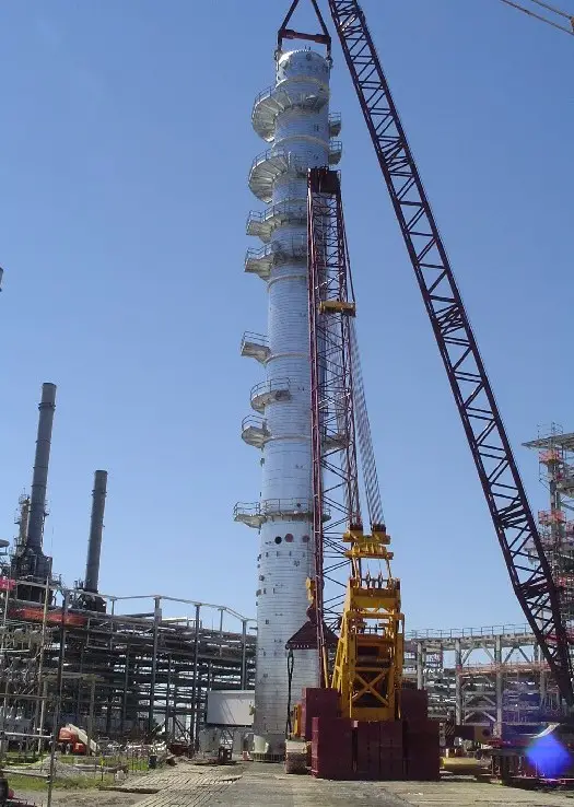
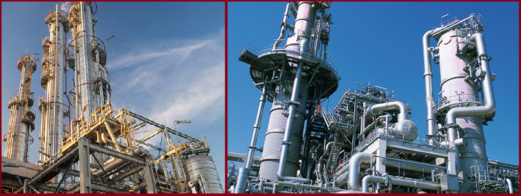
Vertical Columns or Fractionating Towers are frequently used in the process units for fractionation and stripping. They are cylindrical in shape and their axis is vertical to the grade. This article will provide guidelines for piping design considerations from such columns or towers.
What is Fractionation?
Fractionation is the process of separating a mixture of different miscible liquids by vaporizing the mix and condensing the constituents at their individual boiling points. The process of distillation has evolved during the century from the Batch shell still process to the Continuous shell still process to the present Fractional distillation process.
Principle of operation of Fractionating tower
Fractionation is the process of separating a mixture by vaporizing the mix and condensing the constituents at their individual boiling points. Higher boiling point liquids will condense first, followed by lower boiling point products. This is achieved in the fractionating tower by creating zones of different temperatures along the length of the tower, the lowest at the top and the highest at the bottom. As the vapors rise along the column, they lose heat and condense at their respective boiling points. Column internal trays / packed beds, accumulators, and draw-offs help in this function.
What are Trays in a Vertical Column?
Trays are stamped plates of steel with unidirectional valves attached to them. They allow the passage of vapor in the upward direction only. They are placed all along the length of the tower. The valve lifts when the vapor force on the bottom of the valve exceeds the liquid force on top of it. As the vapors push the valves and pass through the liquid, vapors with higher condensation points lose heat and condense. The excess liquid on the tray flows down to the lower tray via a downcomer. Lighter boiling fractions in this liquid are vaporized on the lower tray by the heat of the upward-traveling vapors. Vaporization and condensation take place all along the length of the tower. Draw-offs at appropriate locations allow the removal of desired products from the column.
What are Packed Beds in a Vertical Column
These are beds of metal rings, packed along the length of the column. They function similarly to trays. Rising vapor passing through the metal rings comes in contact with liquid flowing down the column. The down-flowing liquid is heated by the upward-flowing vapor similar to trayed columns.
Design Considerations for Vertical Columns Piping Layout
Column Piping Layout: Locating the column
The piping designer should economize piping interconnections between the column and its adjacent pieces of equipment (pumps, condensers, heaters, reboilers, etc.) when locating the column. The following documents are needed to locate the column on the plot plan.
The column is located on the plot plan as per the process sequence dictated by the P&ID. Small columns can be placed on stand-alone structures. Large columns need a civil foundation of their own. In plants where the related equipment is housed, they are placed adjacent to the building or structure. Columns are best located on either side of the pipe rack, serviced by auxiliary roads for maintenance access. Vessel transportation, erection, and other constructibility issues should also be looked into while finalizing the location of the vessel. Adequate space must be provided around the column for operator movement and maintenance access. Locating close to an access road to reduce maintenance efforts. Interdistances between adjacent pieces of equipment are fixed as per Table 5 of Piping & Plant Layout Specification. The Bottom Tan Line elevation is fixed by the P&ID. The same may be increased to facilitate piping and equipment layout in consultation with the Process group.
After the column has been located on the plot plan, the following jobs are carried out.
- Column elevation review and support selection
- Tray orientation
- Nozzle orientation
- Platform and access requirement
- Support cleat location detailing
- Lifting lugs and earthling lugs location planning
- Finalizing Vessel Name Plate location
Column Piping: Column elevation review and support selection
The Bottom Tan Line elevation fixed by the P&ID is the minimum elevation required for NPSH of the bottom pumps. This may be increased in consultation with Process Group for the following.
- Operator Access – Proper headroom clearance should be available for safe operator access to the column.
- Maintenance Access– Proper maintenance access clearance should be available for the safe movement of maintenance equipment around the column.
- Minimum clearance as per piping layout
- Bottom nozzle size – The bottom nozzles are connected to the bottom head with a straight pipe piece and a 90(elbow. This lowers the clearance available below the bottom of the elbow
- Bottom head details (elliptical, hemispherical, etc.) The hemispherical head has a depth twice as compared to the elliptical (2:1) This will change the centerline elevation of the bottom nozzle and consequently the clearance under the elbow.
- Vertical thermosyphon reboiler connections -The Reboiler bonnet removal area dictates the minimum tan line elevation of the column when the reboiler is attached to the column.
Column Piping: Supporting Arrangement of Vertical Column
Columns are generally supported by the following methods
- Skirt Supported with a foundation on grade – most preferred. Skirts are straight for short columns and flared for tall ones.
- Ring girder supported – On tabletop (when the bottom nozzle needs to be accessed)
- Skirt supported – On the tabletop
- The choice of support may fix the column elevation for some layouts.
Tray orientation on Column Piping
The following documents are required for orienting the trays.
- Vessel Process sketch & Tray data (No. Of pass, downcomer area, tray spacing, etc)
- P&ID
- Plot plan
- Plant Layout Specification
Vertical Column Piping: Tray nomenclature
- Odd and Even trays – Trays are numbered from the top of the column to the bottom. Trays with odd numbers 1,3,5 are the odd trays and those with even numbers 2,4,6, are the even trays.
- Number of Passes – Trays can be One-pass, Two-pass, Three-pass, or Four-pass depending on column diameter.
- Active Area (Bubbling area) – Area of the tray, which allows vapor to pass thru it
- Downcomer area – The area allows excess liquid on one tray to flow down to the tray below it.
- Tray spacing – Interdistance between adjacent trays.
- Chimney tray – It is a solid plate with a central chimney section and is provided at the draw-off sections of the column.
Column Piping Layout: Tray orientation considerations
The main items influencing tray orientation are
- Feed nozzle orientation
- Reboiler location
- Access Manholes
Feed nozzles are large in diameter and their orientation is fixed by the piping layout. The feed nozzle may have one or multiple external connections with different internal configurations for the following:
- One nozzle with two orientations
- Two nozzles with two orientations
- One nozzle with multiple orientations
It is of utmost importance that the feed nozzle is parallel to the tray downcomer. The reboiler location is fixed on the plot plan. Now, as the reboiler draw-off nozzle is mostly located on the same side as the reboiler to minimize piping run, the draw-off orientation is established. The reboiler returns the nozzle to be parallel to the tray downcomer. For the bottom draw-off nozzle arrangement, tray orientation remains unaffected. Access Manholes on the cylindrical section are best located towards areas of direct maintenance access and opposite pipe racks. Thus their location may dictate the orientation of the trays.
Vertical Column Nozzle orientation
The following documents are required for orienting the nozzles.
- Process vessel sketch
- Level co-ordination diagram
- P&ID
- Plant layout specification
- Nozzle summary
- Insulation requirements
- Plot plan
General considerations for locating nozzles in Column Piping
Generally, the following nozzles are present on all columns.
- Feed Inlet
- Bottoms Outlet
- Drain
- Vapor Outlet
- Vent
- Reboiler Draw off
- Reboiler Return
- Product Draw off
- Reflux
- Instrument Nozzles
- Steams Out Nozzle
- Access Manholes
Orienting the nozzles
While orienting these nozzles the following points are to be considered.
- The feed inlet is to be placed parallel to the downcomer tray as discussed in tray orientation. The orientation of the feed inlet is in the sector towards the pipe rack from which the feed piping is coming. Proper support and flexibility should be available to route the piping.
- Bottoms Outlet will be on the bottom head, best located on the center of the head. This is of gooseneck type for vessels with skirt-type support and the nozzle flange has to be brought outside the skirt. A separate drain nozzle at the bottom head but a tapped nozzle on the bottom outlet is most preferred. Orientation is generally chosen to minimize piping to the bottom pump keeping the line flexible enough from a stress point of view.
- The vapor outlet, PSV connections, and Vent will be on the top head of the column. The vapor outlet is best located in the center of the head, though it may have to be shifted based on some layout considerations as explained. A large diameter makes the location of the vapor nozzle critical. The nozzle may have to be offset from the center of the column so that, after two elbows, the piping travels down the column at a practically supportable distance from the column.
- The reboiler draw-off nozzle is mostly located on the same side as the reboiler to minimize piping run, thus the draw-off orientation is established. For the bottom draw-off nozzle arrangement, the best-suited orientation as per the piping layout may be chosen.
- The re-boiler return nozzle is to be parallel to the tray downcomer as discussed in tray orientation.
- Reflux nozzles are to be oriented for proper and even flow of refluxed liquid on the bubbling area. This can be achieved by internal distributor piping.
- Level Instrument nozzles should be oriented as close to any inlet nozzle as possible to avoid the effects of turbulence. When baffles are provided this consideration is relaxed.
- Pressure tapping for vapor pressure should be oriented in the bubbling area of the tray above it.
- Temperature tapping for liquid temperature measurement should be oriented in the downcomer area. They are best oriented perpendicular to the tray downcomer. When multiple temperature elements are required, they are best placed at the same orientation but at different elevations. Care must be taken to ensure that the internal projection of the temperature element does not hit the downcomer. The nozzle should be made hillside if the probe length cannot be accommodated in the radial direction.
- Inaccessible Instrument nozzles to be oriented near ladders (location of ladder and Instrument nozzles to be decided concurrently)
- Steam-out connection should preferably be hillside type on the cylindrical shell so that swirling action is generated inside the vessel. This will ensure faster steam out of the column. These should be placed as close to the bottom tangent line as possible.
- Access manholes can be located at the following places, depending on the type of access required in the column.
- On the top of the column. (In this case, the vent can be located on the blind flange of the access manhole.)
- On the cylindrical portion of the column (radially or hillside), this is the most preferred location. The orientation of the manhole should be such that the manhole faces the maintenance access area. This is to be in conjunction with tray orientation. Manhole entry should be directly in a bubbling area and never in the downcomer area. Internal piping should not block the access area of a manhole.
It should be verified that the davit swing area of the manhole cover does not obstruct the movement of maintenance personnel and does not hit any instruments or instrument nozzle connections. The centerline of the manhole should be between 600mm to 1000mm (ideally 760mm) from the top of the service elevation of the vessel.
- A Gooseneck nozzle for a Vapor outlet should be considered when the piping layout is fixed and requires an elbow immediately at the nozzle. This can be a flanged type, thus acting as a manhole also for big nozzle diameters. Flange-type nozzles have the added advantage that their orientation can be changed even after the delivery of the vessel at the site.
- Skirt access manholes are to be oriented for easy access.
- Skirt vents are to be oriented in such a manner so that they do not come at the same location as the access ladder.
Nozzle standouts
Nozzles on the top of the column should have their flange a minimum of 180mm and a maximum of 1000mm from the TOG of the access platform. Nozzle standouts on the shell are calculated on the clearance requirement for maintenance access to nuts on the back of the flange. Due consideration is to be given to vessel insulation when calculating the standout. This standout will be confirmed by mechanical so that the nozzle passes the mechanical requirements.
Preparing the Nozzle Orientation Document
This document should show the plan, and if required, the elevation of the vessel with the location of nozzles on the same. Nozzle orientation is to be from plant north and taken clockwise. Dimensioning should show the radial distance of the vessel flange from the vessel center. A nozzle summary table indicating the Nozzle number, service, size, rating, flange face, elevation from the bottom tan line, and stand out from the vessel center is to be included in the drawing. For nozzles on the vessel heads, the F/F stand out from the bottom or top tan line should be given. In lieu of elevation from the bottom tan line.
Miscellaneous Data to be included in Nozzle Orientation Document
Lifting Lugs
Generally, columns can be lifted with two lugs welded below the top tan line. A tailing lug is to be provided near the bottom of the skirt for tailing operation. The preferred locations should be marked on the nozzle orientation drawing.
Earthing Lugs
Two earthing lugs, ideally 180° apart should be provided on the lower portion of the skirt. The same should be marked on the nozzle orientation drawing.
Name Plate
The nameplate should be located at a prominent location and marked on the nozzle orientation drawing. Care should be taken that the nameplate projects outside the vessel insulation.
Vessel Insulation Clips
Indicate that insulation clips/rods are required for holding the vessel insulating bands.
Platforms and Access Ladders
Platforms are required for the following purposes
- Operational access to valves and instruments etc.
- Maintenance access to manholes.
- Mid landings (when the elevation difference between two platforms exceeds 9m)
Calculating the TOG elevation
The platform on the top head of the column
TOG elevation from the top of column head = Insulation thickness + 50mm clearance + Platform member depth (assume 200mm minimum) + 30mm grating. Round off to the next higher multiple of 10.
Platforms on the cylindrical portion of the column
- Nozzles – Platform to be 500mm (minimum) below the bottom of the flange of the nozzle.
- Instruments (LT/LG) and their standpipes – Platform to be 200mm below the lowest process drain on any of these items.
- Access manholes – The platform is to be ideally 750 mm below the centerline of the manhole. The acceptable range is 600mm to 1500mm below the centerline of the manhole.
- Mid-landing platforms are to be provided when the elevation difference between two platform levels exceeds 9m. The mid-landing is to be ideally evenly placed between the two platforms.
- Two platforms being serviced by a single ladder should ideally have an elevation difference of 600mm between them.
- The platform elevations (TOG) should be rounded off to the nearest multiple of 10.
Platform sizing
The platform on the top head of the column
This platform should be rectangular. It should cover all the nozzles, instruments davits, etc. that need access for operations and maintenance. Ideally, a space of 750mm should be provided around 3 sides of a nozzle. This may be lowered at the discretion of the piping lead. Side entry access to the platform should be the first preference when deciding the exact shape of the platform. Orienting the platform axis along the ladder orientation and providing an extended landing point may achieve this.
Platforms on the cylindrical portion of the column
Determining the Orientation angles
- This platform should be circular. Its orientation extent should cover all the nozzles, instruments davits, etc. that need access for operations and maintenance. The platform should extend beyond the centerline of the manhole by a minimum of 1 manhole diameter.
- A free landing space of 750mm is to be provided for access ladders.
- Ideally, a space of 750mm should be provided around the sides of a nozzle. This may, however, be lowered to 600mm at the discretion of the piping lead.
Determining the width
- The inner radius of the platform should clear the column insulation by 50mm.
- Platform width is dictated by operator access requirements. The following considerations are to be taken care of when deciding the width.
- The minimum platform width is to be 750mm(free of all obstructions).
- The width of the manhole platform is to be a minimum of 900mm.
- Platforms may be locally extended width-wise at regions where vertical pipes pierce the platform, maintaining 750mm clear space from the insulation of piping to the handrail of the platform.
- When controls are located on the platform, the width of the platform is to be 900mm plus the width of the controls.
Platform bracket orientation
Platform support brackets are to be oriented so that they clear the vertical piping traveling down the column, through the platform. Support bracings for platforms at all elevations should be maintained the same as far as possible.
Access ladder
- Access ladders are to be vertical. They should have a clear climbing space of 680mm. Toe clearance from the centerline of the ladder rung to any obstruction to be 230mm. Special care is to be taken for vessel stiffeners.
- A cage is to be provided for all ladders at an elevation of 2300mm and above. Side entry ladders are the first preference.
- The ladder is to be oriented so that it can also be utilized for access to instrument connections that are inaccessible from the working level.
- Inclined ladders are permissible on inclined portions of the skirt and column. The angle is limited to 150 from vertical.
Preparing the Platform Input Document
Platform and Access ladder input is transmitted to Civil via a platform input drawing.
Platforms on the top head of the column
This should clearly indicate the TOG elevation from bottom T/L, dimensions of the platform, and its location w.r.t. The vessel centerlines. Grating cutout requirements (indicating size, shape, and location), required swing direction of the self-closing gate, and davit location need to be marked on the same drawing. Any pipe supports intended to be taken from the platform should be marked.
Platforms on the cylindrical portion of the column
This should clearly indicate the TOG elevation from bottom T/L; the dimensions of the platform (orientation angles and width), and its outer radius from the vessel axis. Grating cutout requirements (indicating size, shape, and orientation), required the swing direction of the self-closing gate. Any pipe supports intended to be taken from the platform should be marked. Orientations of access ladders should be marked on the respective platform elevation plans.
Orienting piping on the face of the column
It is imperative that the orientations, arrangement, and standouts of various piping traveling down the face of the column are calculated keeping in mind the following points.
Large diameter columns
- Piping has to be arranged in the order of the elevation and orientation of the nozzles.
- The piping of these columns can travel down the column radially, with independent supports.
- The clear minimum space between the pipe and shell is to be 300 mm excluding any insulation.
- The pipe with insulation should clear the stiffening ring and its insulation.
- The minimum orientation angle between two adjacent pipes should be calculated to clear the support bracket of one pipe hitting the insulation cladding of the adjacent pipe.
- Support points of adjacent piping should be offset to save space between them. as the support brackets will have to be oriented so that there is no clash between the cleats of the supports or between the support members and bracings.
Small diameter columns
- Piping has to be arranged in the order of the elevation and orientation of the nozzles.
- Small-diameter columns have an inherent problem of supporting and guiding each line independently due to the small circumference available for the piping. After the first rest support near the nozzle, the pipes should be oriented as though they are traveling down a vertical pipe rack.
- The clear minimum space between the back of the pipe or shoe and shell is to be 600mm. On the vertical run, minimum spacing requirements have to be followed.
Supporting Piping from Vertical Columns
Piping should be supported from the vessel or its platform when it is difficult to construct civil support from grade or adjacent structures at the required location. Vessel support may also be taken to take advantage of lower differential thermal growth between vessel and piping, as compared to piping and civil support. A judicious selection of support locations can eliminate the requirement for springs.
Thumb rules for supporting piping from columns
- Small loads can be transferred directly to the platform members. These include rest, one-way stop, two-way stop, or hold-down supports and the piping layout should be done accordingly.
- Large loads should be transferred to the vessel shell and the piping layout should be done such that the platform members do not interfere with these independent supports.
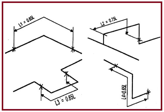
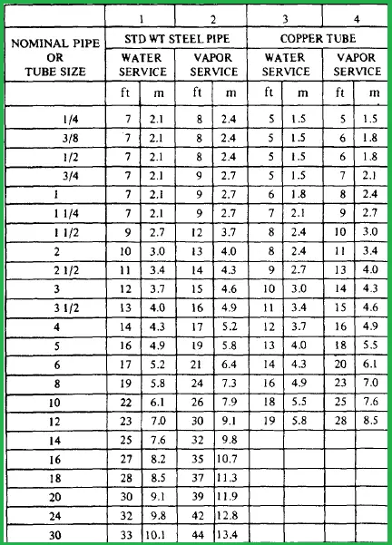
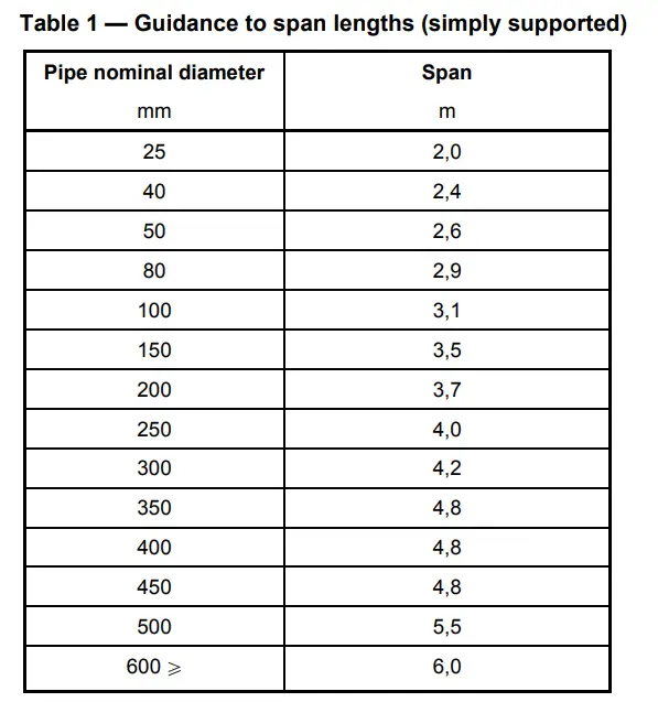
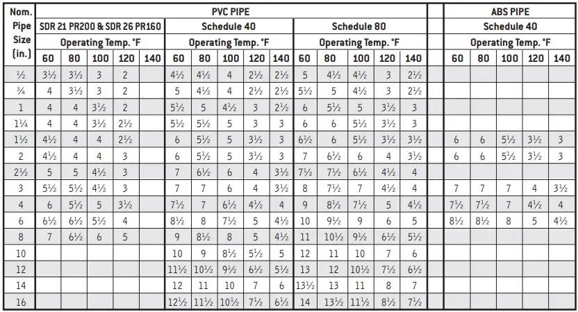
- The first piping support is Rest support and it should be as close to the equipment nozzle as possible. The second and subsequent supports are guides and they are to be located as per the allowable piping spans available in the tables. For tall columns, another rest support may be needed. This is done by providing spring support which will take care of the differential expansion of the vessel and piping.
- Piping support should not cause any hindrance to the movement of personnel.
- Vessel growth should be considered to check the clash of piping support with any adjacent piping or structure.
Types of supports for Column Piping
Supports welded to piping
Horizontal trunnions welded to the pipe take the vertical load of the pipe. They are generally used in pairs, set apart at 180°. Their axis is perpendicular to a line drawn from the center of the column to the center of the pipe at the location of support. Trunnion lengths should be adequate enough so that their ends project 50 mm from the outer edge of the support bracket member Shoes are provided for guidance purposes and to prevent insulation cladding from hitting the support bracket member. Adequate shoe length is to be taken for differential movement of pipe and vessel.
Supports welded to the vessel
Support brackets( non-braced and braced ) and Guide brackets( non-braced and braced ) are the most common support arrangements for vertical piping.
Calculating the minimum dimensions of support members
Load bearing supports
Trunnions or springs transfer load to these supports. Minimum clear inside dimensions are calculated so that the insulation cladding is 50 mm away from the inside of the structural member or support plate of the spring.
Guide supports
The bare pipe is guided directly by the guide bracket. Shoes are provided in pairs,180° apart, for lines with insulation. These can be single pairs or double pairs depending upon the type of guiding required at that particular location. The guide gap required by stress is to be added to the end-to-end-to-end dimensions of bare pipe or pipe with shoes.
Preparing the Civil Pipe Support (CPS) Input Document
CPS input is transmitted to Civil and Mechanical via a CPS input drawing. A sketch clearly indicating the TOS, dimensions, and CPS location with respect to the vessel centerline needs to be drawn. Any requirement for additional support plates for springs or trunnions is to be indicated. A summary table indicating the CPS number, TOS, stress file number, and corresponding node number from the Nozzle cleat load information chart needs to be created. The Nozzle cleat load information chart indicates the various loads acting at the support location under various conditions. It is to be attached along with the CPS input document.
Few more Resources for you..
Stress Analysis of Column piping system using Caesar II
Piping Design and Layout Considerations
Piping Materials Basics
Piping Stress Analysis