What is Pressure Testing?
Pressure testing is a process of verifying the strength, integrity, and safety of a pressurized system or component. It involves pressurizing the system or component with a fluid or gas, usually water or air, to a predetermined level and monitoring the pressure to ensure that it remains stable over a specified period of time.
The purpose of pressure testing is to identify any leaks or weaknesses in the system or component that could lead to failure under normal operating conditions. By subjecting the system or component to a higher pressure than it would normally experience, any weaknesses or defects in the material or construction can be detected.
There are several types of pressure tests, including hydrostatic testing, pneumatic testing, and vacuum testing. Each type of test is designed to assess different aspects of the system or component, such as its ability to withstand pressure, its resistance to leaks, and its overall integrity.
Pressure testing is commonly used in a wide range of industries, including oil and gas, manufacturing, construction, and aerospace. It is a critical step in ensuring the safety and reliability of pressurized systems and components.
Hazards of Pressure Testing
Everybody knows that Pressure Testing (Hydro test, Pneumatic Test, or Pressure Test) is a highly hazardous activity and there are many examples of incidents that had already happened. So the utmost care must be exercised to manage safety during pressure testing.
While pressure testing is an important safety measure to ensure the integrity of pressurized systems, it also involves certain hazards that should be taken into account to prevent accidents and injuries. Some of the hazards associated with pressure testing include:
- Explosion or rupture: If the system or component being tested is unable to withstand the pressure, it may explode or rupture, causing damage to the equipment and potential injury or death to anyone nearby.
- Projectile hazards: If a component fails during the test, it may release fragments or debris at high velocity, which can cause serious injury or damage to equipment and structures.
- Chemical hazards: The fluid or gas used to pressurize the system may be hazardous if it leaks or is released, potentially causing chemical burns or respiratory problems.
- Noise hazards: The noise generated during pressure testing can be very loud, potentially causing hearing damage if proper hearing protection is not used.
- Thermal hazards: The pressurized fluid or gas may generate heat during the test, potentially causing burns or other thermal injuries.
To prevent these hydro testing hazards, proper safety measures should be taken, including wearing appropriate personal protective equipment (PPE), maintaining a safe distance from the test area, using proper containment and ventilation measures, and following established safety procedures and protocols. It is also important to ensure that the equipment used for pressure testing is properly maintained and calibrated to prevent accidents and ensure accurate results.
In the below paragraphs, We will provide examples of five such incidents that can be used to understand the hazards and dangers involved during pressure testing.
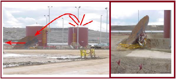
Hydro-test of a new vertical vessel
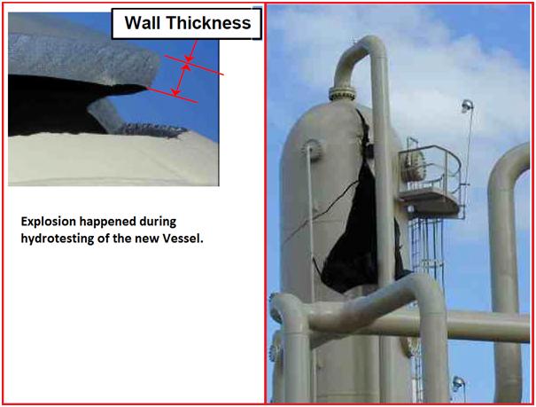
Refer to Fig. 1. The image shows an exploded vessel that happened during hydro testing of a new vessel. The root cause of the incident is not known fully. But there was some brainstorming and people thought that hydro-testing with “very cold” water could be a contributing factor. The good news is that no injuries occurred.
Learning from the Incident
It is learned that water temperature during hydro testing is critical. It is suggested to maintain the metal and water temperature at least at 16°C or at least 10°C above the impact test temperature of the metal during pressure testing.
Filling of a vertical tank
This incident happened while filling the tank (Refer to Fig. 2) with water from a fire hydrant. As the relief valve could not displace the air fast enough for the volume of water that was being pumped in, The top of the tank blew off suddenly.
Fortunately, no injury happened, but an operator was on top of the tank a few seconds before.
Lessons Learned from the Incident
Before filling and emptying operations, drain and venting systems must be thoroughly inspected and checked.
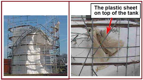
Emptying a vertical tank
Refer to Fig. 3. While the tank was being emptied, it suddenly collapsed. Root cause analysis shows that a plastic sheet that was protecting the roof was trapped in the vent which created a vacuum. So it is a must to inspect the venting systems before filling and emptying operations.
There was no injury. It should be noted that this type of incident is not that unusual.
Sphere collapse
During the filling of a 2000 m3 LPG sphere (Fig. 4), Its legs suddenly collapsed. One nearby person was killed and one was seriously injured.
The research found that the sphere was approximately 80% full of fresh water. The vessel’s last hydro-test was 10 years ago and the last inspection of its legs was done 5 years ago.
The main cause was the Severe corrosion of the legs under the concrete fire protection. The corrosion occurred due to water ingress between the concrete and the steel legs. The water protective cap that was located over the concrete was not sufficient to keep the water out. It was verified later that the steel legs had their thickness reduced by up to 8 mm, with pitting holes of up to 10 cm2.
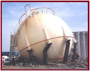
Thorough investigation and tests confirmed that the following factors contributed to the sphere collapse:
- The poor design of the water caps over the fire-proofing concrete was allowing the water to penetrate the steel beams and the concrete.
- Vertical cracks in the concrete let water in.
- Poor workmanship during Repairs had been done to the concrete.
- The new concrete had not adhered to the old concrete, again letting water in.
- The deluge system had been tested with saltwater, increasing the possibility of corrosion.
Learning from the incident
A complete inspection must be performed visually and if required with NDT before pressure testing of an old vessel. This inspection must include the vessel, nozzles, appurtenances, and supporting structures.
Emptying of a gearbox
To speed up the removal of 250 liters of oil from a gearbox (Fig. 5), the gauge hole was plugged and the breather was connected to the 6-bar air network. The gearbox exploded and threw missiles around seriously damaging surrounding piping and structure. Fortunately, there was no injury.
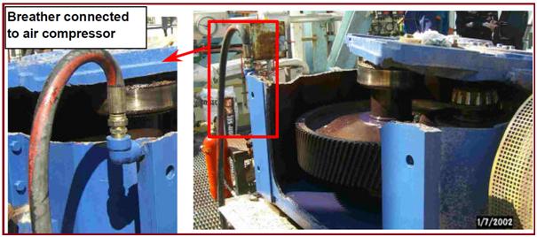
Even though a gearbox is not a pressure vessel, its productivity may lead to a risky attitude.
Recommended Actions for Pressure Testing
Tests may be a routine operation pressure but do not forget that in fact, pressurization is energy storage. Its instantaneous release works like a bomb and may cause severe damage to persons and equipment.
Good preparation is always essential to avoid incidents. It is recommended to use the following checklist:
- Based on relevant standards and specifications, A detailed checklist procedure must be prepared which shall cover the testing operation from filling up to emptying the vessel.
- Good coordination is of utmost importance to avoid performing the hydro-test at the same time as other operations. Most reputed companies use work permit procedure / Job Hazard Analysis methodology.
- The equipment must be in good condition and adequately maintained and certified.
- Testing equipment shall be kept as far as practicable from the recording and pumping station.
- New Testing equipment must be checked before using it.
- The test area must be roped off,
- During the test, from filling up until the end of depressurization, all non-essential people must be out of the test area,
- The test crew must attend a toolbox talk,
- Wearing PPE must be made mandatory for all personnel involved in testing.
- Leak inspection must be performed at least 15 minutes after the test pressure has been reached and this has to be inspected only by designated personnel.
- While under pressure or during pressure-up stages, never tamper with, or tighten any fittings (i.e. connections, bolts, hoses, etc).
Few more useful resources for you…
What is Engineering Process Safety?
Safety Rules during A Field Visit By A Design Engineer
An article on Crane safety during Construction
HAZOP (Hazard and Operability) Study: A brief introduction
An article on Excavation Hazards at Construction Sites
Hazardous Area- Theory, Classification and Equipment selection: A short presentation