Calculation of the minimum wall thickness of a given pipeline diameter and selection of actual thickness is one of the most important basic design considerations for any pipeline project. This is one of the basic activities that is performed at the initial stages of any detailed design project. In this article, the pipeline wall thickness calculation methodology will be explained for a liquid pipeline of 10-inch diameter (API 5L-Gr X52, 10.75-inch OD, Design Pressure=78 Bar-g, Design Temp=60 Deg. C) with a sample example.
Criteria for Minimum Pipeline Wall Thickness Calculation
The wall thickness for the CS Line pipe shall be calculated based on permissible hoop stress due to internal pressure. In accordance with ASME B31.4, clause 403.2.1, The nominal wall thickness of straight sections of steel pipe shall be equal to or greater than tn determined by the following
Equation : tn ≥ t + A
Here
- A: sum of allowances for threading, grooving, corrosion, and erosion and an increase in wall thickness if used as a protective measure
- tn: nominal wall thickness satisfying requirements for pressure and allowances
- t: pressure design wall thickness as calculated in inches (millimeters)
The line pipe wall thickness (t) to withstand the internal design pressure is calculated as below:
t = P * D / (2 * F *S * E)
Where
- t : Calculated Wall thickness (mm)
- P : Design pressure for the pipeline (kPa)=78 bar-g=7800 KPa
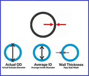
- D : Outside diameter of pipe (mm)= 273.05 mm
- F : Design factor = 0.72
- S : Specified Minimum Yield Strength (MPa)=359870 KPa for the specified material.
- E : Longitudinal joint factor = 1.0
Hence Calculated wall thickness (t, mm) = (7800*273.05)/ (2*0.72*359870*1) = 4.10
If the sum of allowances for threading, grooving, corrosion, and erosion and an increase in wall thickness is used as a protective measure=0.3 mm
Then nominal wall thickness satisfying requirements for pressure and allowances= 4.1+0.3= 4.4 mm.
So, any available thickness greater than 4.4 mm can be used as a selected thickness.
Now various organizations have their own guidelines for minimum thickness selection considering pipe rigidity, supporting, handling, field bending, and other aspects relating to construction and in-situ integrity of the pipeline and those need to be checked. Based on these, certain checks need to be performed before deciding the final wall thickness. These are listed below:
Some organizations limit the use of metallic line piping with a thickness of less than 4.8 mm. Hence 4.8 mm will be the selected thickness.
The diameter-to-wall thickness ratio should not exceed 96 for metallic pipelines for some organizations. Here D/T=273.05/4.8=56.88. In general, most codes inform to keep the D/T ratio less than 100 as additional checks will be required for to consider when D/T is equal to or more than 100.
Full Vacuum Collapse check
As per some organizations, collapse due to vacuum conditions shall be accounted for in the design of all pipelines, even when vacuum conditions are not expected to occur in service.
The calculations are carried out following pressure vessel code ASME Section VIII, DIV 1, UG-28. All vacuum collapse calculations are carried with nominal wall thickness excluding corrosion allowance.
As per UG 28 (f) of ASME section VIII, the selected pipeline wall thickness will be safe for full vacuum, if it is capable of withstanding a net external pressure of 1.01325 bar (15 psi).
Now following UG 28 equations (ASME BPVC Sec VIII) and graphs calculate allowable external working pressure. If the allowable external working pressure is more than the design external pressure (i.e., 1.01325 bar) then the selected thickness is satisfactory.
Equivalent Stress check
The equivalent stress calculations must be carried out as per ASME B31.4.
The wall thickness initially derived from hoop stress considerations based on design factors, should be such that the longitudinal, shear, and equivalent stresses in the pipe wall under functional and environmental loads do not exceed certain values. This is covered in ASME B31.4 Article 402 and ASME B31.8 Article 833. Because the requirements in these various articles differ from each other, it is recommended to use a single approach for all pipelines as detailed below.
The equivalent stress can be defined as follows:
Seq = (Sh2 + SL 2– ShSL+ 3Ss2)1/2 (Von Mises equation)
- Seq = equivalent stress
- Sh = hoop stress (due to pressure)
- SL = longitudinal stress (due to pressure, thermal expansion, and bending)
- Ss = combined shear stress (due to torque and shear force)
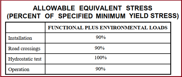
The stress calculations for the operational phase shall be carried out with the nominal wall thickness excluding the corrosion allowance. The equivalent stress shall not exceed the values given below:
Pipeline Wall Thinning Criteria Check
Changes in direction may be made by cold bending of pipe or installing factory-made bends or elbows. The bending of the pipe will result in a significant wall thinning. Hence, the wall thickness of finished bends, considering wall thinning at the outer radius, should be not less than the calculated wall thickness for Hoop Stress. The wall thinning calculations should be carried out following BS 8010.
As per BS 8010, An indication of wall thinning as a percentage can be calculated using the following equation:
Bend Wall Thinning =50/(n+1), %
This formula does not take into account other factors that depend on the bending process, and the bend manufacturer should be consulted where wall thinning is critical.
Here,
- n=inner bend radius (Ri) divided by pipe outside diameter(D) for wall thinning formulae
- Ri=Inner bend radius=(Bend Radius)-(OD/2)
- The value of bend thinning shall be less than 2.5%.
Pipeline Strain Check
The strain induced in a pipeline by bending it along a radius R is =(Pipe OD)/2R (Bend Radius) the permanent bending strain should be within 2%.
Online Course on Pipeline Thickness Calculation
If you want to learn more and wish to check a case study, then I can suggest the following online video course which provides an example of pipeline thickness calculation for both restrained and unrestrained pipelines.
Pipeline Thickness Calculation Methodology with Example
Steel Pipeline Wall Thickness for Gas Pipelines
The pipeline wall thickness for gaseous products is calculated based on ASME B31.8, clause 841.1.1. The formula (When D/t>=30) is mentioned below:
- t=(PD)/(2SFET) as per US unit or
- t=(PD)/(2000SFET) in SI units.
Here,
- t = nominal wall thickness, in. (mm)
- D=nominal outside diameter of pipe, in. (mm)
- E=longitudinal weld joint quality factor obtained from Table 841.1.7-1
- F=design factor obtained from Table 841. 1.6- 1
- P=design pressure, psig (kPa)
- S=specified minimum yield strength, psi (MPa),
- T=temperature derating factor obtained from Table 841.1.8-1
Differences between Pipeline Thickness Calculation as per ASME B31.4 and ASME B31.8
The methodology applied in pipeline wall thickness calculation for liquid pipelines and gas pipelines is almost similar. Only there are two major considerations:
- Consideration of Temperature Derating Factor: As liquid pipelines operate below 120 Degrees C as per ASME B31.4, the effect of temperature is not considered in the pipeline thickness calculation equation as per ASME B31.4. However, as gases can operate at higher temperatures (up to 232 Degrees C), the temperature effect is considered by using a factor known as the temperature derating factor. The value of the temperature derating factor up to a temperature of 120 degrees C is equal to 1.0 means both equations become the same below 120 degrees C temperature.
- Consideration of Design Factor: In general, the design factor for ASME B31.4 is 0.72 which is constant. However, in ASME B31.8 the design factor varies with respect to location class decided based on density of population and inhabitance.
The major differences between the pipeline wall thickness calculation as per liquid transportation pipeline code (ASME B31.4) and Gas Transportation Pipeline Code (ASME B31.8) are tabulated below:
| Aspect | ASME B31.4 (Liquid Pipelines) | ASME B31.8 (Gas Pipelines) |
|---|---|---|
| Scope | Liquid hydrocarbons, anhydrous ammonia, other liquids | Natural gas, hydrogen gas, and other gases |
| Design Factor (F) | Standard 0.72, reduced in populated areas | 0.72 (Class 1), 0.60 (Class 2), 0.50 (Class 3), 0.40 (Class 4) |
| Wall Thickness Formula | t=PD/2SFE | t=PD/2SFET |
| Temperature Derating Factor | Not Applicable as the temperature limitation is up to 120 Deg C | Applicable when the gas temperature is more than 120 degrees C. Up to 120 degrees C the value of Temperature derating factor T is equal to 1. |
| Location Classes | Simplified, with design factor reductions in sensitive areas | Detailed location class system with varying design factors |
| Safety Considerations | Lower safety margins due to the nature of liquid transport | Higher safety margins due to the explosive nature of gases |
| Material Stress | Focus on material suitability for liquid transport | Emphasis on preventing brittle failure, considering gas-specific factors |
| Testing & Inspection | Hydrostatic testing at 1.25 times design pressure | Hydrostatic testing at 1.5 times design pressure, more stringent inspections |